EP0187101A2 - Zusammenklappbarer Schlüssel für Fahrzeuge - Google Patents
Zusammenklappbarer Schlüssel für Fahrzeuge Download PDFInfo
- Publication number
- EP0187101A2 EP0187101A2 EP85402599A EP85402599A EP0187101A2 EP 0187101 A2 EP0187101 A2 EP 0187101A2 EP 85402599 A EP85402599 A EP 85402599A EP 85402599 A EP85402599 A EP 85402599A EP 0187101 A2 EP0187101 A2 EP 0187101A2
- Authority
- EP
- European Patent Office
- Prior art keywords
- cap
- key
- key body
- recess
- bearing
- Prior art date
- Legal status (The legal status is an assumption and is not a legal conclusion. Google has not performed a legal analysis and makes no representation as to the accuracy of the status listed.)
- Granted
Links
Images


Classifications
-
- E—FIXED CONSTRUCTIONS
- E05—LOCKS; KEYS; WINDOW OR DOOR FITTINGS; SAFES
- E05B—LOCKS; ACCESSORIES THEREFOR; HANDCUFFS
- E05B19/00—Keys; Accessories therefor
- E05B19/04—Construction of the bow or head of the key; Attaching the bow to the shank
- E05B19/043—Construction of the bow or head of the key; Attaching the bow to the shank the shank being pivotably mounted on the bow, e.g. for storage
-
- Y—GENERAL TAGGING OF NEW TECHNOLOGICAL DEVELOPMENTS; GENERAL TAGGING OF CROSS-SECTIONAL TECHNOLOGIES SPANNING OVER SEVERAL SECTIONS OF THE IPC; TECHNICAL SUBJECTS COVERED BY FORMER USPC CROSS-REFERENCE ART COLLECTIONS [XRACs] AND DIGESTS
- Y10—TECHNICAL SUBJECTS COVERED BY FORMER USPC
- Y10T—TECHNICAL SUBJECTS COVERED BY FORMER US CLASSIFICATION
- Y10T70/00—Locks
- Y10T70/70—Operating mechanism
- Y10T70/7441—Key
- Y10T70/778—Operating elements
- Y10T70/7791—Keys
- Y10T70/7876—Bow or head
-
- Y—GENERAL TAGGING OF NEW TECHNOLOGICAL DEVELOPMENTS; GENERAL TAGGING OF CROSS-SECTIONAL TECHNOLOGIES SPANNING OVER SEVERAL SECTIONS OF THE IPC; TECHNICAL SUBJECTS COVERED BY FORMER USPC CROSS-REFERENCE ART COLLECTIONS [XRACs] AND DIGESTS
- Y10—TECHNICAL SUBJECTS COVERED BY FORMER USPC
- Y10T—TECHNICAL SUBJECTS COVERED BY FORMER US CLASSIFICATION
- Y10T70/00—Locks
- Y10T70/80—Parts, attachments, accessories and adjuncts
- Y10T70/8432—For key-operated mechanism
- Y10T70/8676—Key holders
-
- Y—GENERAL TAGGING OF NEW TECHNOLOGICAL DEVELOPMENTS; GENERAL TAGGING OF CROSS-SECTIONAL TECHNOLOGIES SPANNING OVER SEVERAL SECTIONS OF THE IPC; TECHNICAL SUBJECTS COVERED BY FORMER USPC CROSS-REFERENCE ART COLLECTIONS [XRACs] AND DIGESTS
- Y10—TECHNICAL SUBJECTS COVERED BY FORMER USPC
- Y10T—TECHNICAL SUBJECTS COVERED BY FORMER US CLASSIFICATION
- Y10T74/00—Machine element or mechanism
- Y10T74/20—Control lever and linkage systems
- Y10T74/20576—Elements
- Y10T74/20636—Detents
Definitions
- the present invention relates to a folding key for vehicles, for turning on and off an ignition switch or the like of the vehicle and, more particularly, to a folding key suitable for use in motor tricycles and four-wheeled buggy vehicles for travelling on a waste or rugged land.
- a folding key for turning on and off an ignition switch provided on a body outer surface of a vehicle of the kinds described above is known from Japanese Utility Model Publication No. 36-12592, for example.
- the folding key comprises a key body, and a cap serving also as a knob and attached to a base of the key body.
- the key body has a base end pivotally mounted on the cap so as to be capable of being raised and levelled with respect thereto to allow the cap to cover a keyhole, in order to prevent dust and rainwater from entering the keyhole.
- An object of the present invention is to provide a folding key for vehicles, in which a cap has a thickness reduced to facilitate the accommodation of the key in a keeping location and to facilitate the carrying of the key.
- Another object of the present invention is to provide a folding key for vehicles, which is arranged and disposed so as not to allow dust, rainwater and the like to easily enter from the outside.
- a still further object of the present invention is to provde a folding key for vehicles, in which should dust, sand or the like enter, it would be possible to smoothly raise and level a key body.
- a folding key for vehicles comprising: a dished cap having a cut-out formed in a portion of a peripheral edge of the cap; a bearing portion provided in the cap; and a key body having one end thereof supported by the bearing portion and capable of pivoting with respect to the cap about the bearing portion, the key body being engageable with the cut-out when the key body pivots ultimately; the cap being arranged on the vehicle so as to allow the key body to be levelled in parallel to an advance direction of the vehicle; and the portion of the peripheral edge of the cap, in which the cut-out is formed, being located at a rear of the peripheral edge with reference to the advance direction of the vehicle.
- a cap has a recess which opens at one end face of the cap.
- a first bearing portion is provided in a bottom surface of the recess.
- a support member is fitted in the recess and has an opening opposed to the bottom surface of the recess and an inner surface opposed to the first bearing portion.
- a second bearing portion opposed to the first bearing portion is provided in the inner surface at opposite sides of the opening.
- a key body extends through the opening in the support member and has a pivot portion pivotally clamped and supported between the first and second bearing portions.
- a resilient member is disposed between the bottom surface of the recess in the cap and the opening in the support member and is resiliently engaged with an inward end of the key body.
- a cut-out is formed in a portion of a peripheral edge of the cap, and the key body is engaged with the cut-out when ultimately levelled with respect to the cap.
- the cap is arranged so as to allow the key body to be levelled in parallel to an advance direction of the vehicle.
- the portion of the peripheral edge of the cap, in which the cut-out is formed, is located at a rear of the peripheral edge with reference to the advance direction of the vehicle.
- Fig. 1 shows a motor tricyle of a buggy type illustrated by way of an example.
- a switch S forming a part of an ignition switch mechanism which includes a spark plug cap 5, an ignition coil 6, etc. are incorporated in an upper surface of an upholder 8 which is provided in a slightly rearwardly inclined manner at a central portion of a handlebar 9 above a top bridge 7.
- the switch S includes, as shown in Fig. 2 illustrating a first embodiment of the invention, for example, a folding key of the invention which comprises a cap 2 in the form of a dish serving also as a knob, a key body 1 pivotally mounted to the cap 2 at a base thereof, and a key cylinder 3 at the side of the upholder 8 into which the key body 1 is to be inserted.
- a folding key of the invention which comprises a cap 2 in the form of a dish serving also as a knob, a key body 1 pivotally mounted to the cap 2 at a base thereof, and a key cylinder 3 at the side of the upholder 8 into which the key body 1 is to be inserted.
- the cap'2 comprises a cylindrical base 2a having a circular recess 2a' which opens at one end face of the base 2a and has such a diameter and depth as to completely cover a head of the key cylinder 3, and a knob portion 2b which is integrally formed on an outer surface of the other end of the base 2a and is adapted to be held by a rider for angularly moving the key body 1.
- the key body 1 is formed into a generally T-shape, and comprises an insert portion la, and a pair of pivot portions lb and lb extending oppositely and laterally from one end of the insert portion la, with bushes 4 and 4 made of brass, for example, being fitted on the pivot prtions 1b and lb, respectively.
- the cap 2 is formed by an integral molding of synthetic resin.
- a pair of bearing bores 2c and 2c (Fig. 5) having a rectangular cross-section, accurately speaking, a generally square cross-section are formed within the cap 2 and extend through a diametrical center thereof in a diametrically opposed manner.
- the pivot portions lb and lb of the key body 1 having fitted thereon the respective bushes 4 and 4 are pivotally fitted in the bearing bores 2c and 2c, respectively.
- the bearing bores 2c and 2c, hence, the pivot portions lb and lb of the key body 1 extend in the same direction as the extending direction of the generally sector-shaped knob portion 2b which is integrally provided on an outer surface of the cap 2 and projected therefrom. Accordingly, the key body 1 pivots in a plane perpendicular to the extending directin of the knob portion 2b.
- a cut-out 2d (Fig. 4) having a rectangular cross-section and having a width slightly greater than the width W of the insert portion la of the key body 1 is formed at a portion of a peripheral edge of the cylindrical base 2a of the cap, which portion corresponds to the levelling direction of the key body 1, so that when levelled, the insert portion la of the key body 1 is received in the cut-out 2d. That is, in the illustrated embodiment, the cut-out 2d is provided in the portion of the peripheral edge which is located perpendicularly to the direction of an arrow A indicating the front of a vehicle body when the key body 1 is inserted into the key cylinder 3.
- the insert portion la of the key body 1 is capable of pivoting through approximately 90 degrees about the pivot portions lb and lb, to thereby enable the key to be folded.
- the key body 1 is raised at right angles with respect to the cap 2 as shown by the solid line in Fig. 5, and the insert portion la is inserted into a keyhole, not shown, of the key cylinder 3 until the cap 2 is fitted on a portion of the head of the key cylinder 3 which extends upwardly from the upholder 8. Subsequently, the rider holds the knob portion 2b of the cap 2 and angularly moves the cap 2 in the directions indicated by arrows B in Fig. 4 to turn on and off the ignition switch.
- each of the bearing bores 2c and 2c is formed into a rectangular cross-section having four corners (a, a', b, b'), clicking effects are obtained upon raising and levelling of the key body, and it is ensured that the key body is retained in predetermined raised positions (a, a') and predetermined levelled positions (b, b').
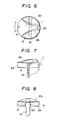
- Figs. 6 through 8 show a second embodiment of the invention, which is identical with the above-described first embodiment in that a cap 2 is mounted on the upholder 8 (Fig. 1) such that a sector-shaped knob portion 2b extends in the advance direction of the vehicle, but is different from the first embodiment in that bearing bores 2c and 2c in the cap 2 and pivot portions lb and lb of a key body 1 extend perpendicularly to the extending direction of the knob portion 2b and, accordingly, the key body 1 is capable of being levelled in the same direction as the extending direction of the knob portion 2b, i.e., in parallel to the advance direction of the vehicle, and a cut-out 2d is formed in a rear edge portion of a cylindrical base 2a of the cap 2 which is located rearwardly with reference to the advance direction of the vehicle.
- the cut-out 2d is so arranged as to be located just at the back with reference to the advance direction of the vehicle when the knob portion 2b is angularly moved to a position where the ignition switch is turned on.
- the entire switch S including the key is mounted on the rearwardly inclined upper surface of the upholder 8 of the vehicle body, it would be difficult for rainwater or the like to enter the interior of the key through the cut-out 2d formed in the rear portion of the cap 2, but rainwater or the like having entered the interior would tend to flow out through the cut-out 2d.
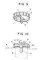
- Figs. 9 and 10 show a third embodiment of the invention, which is different from the above-described first and second embodiments only in that an insert portion la of a key body 1 has a length less than an inside diameter R of a cap 2 and the insert portion la is completely accommodated within the cap 2 when the key body 1 is levelled.
- the third embodiment is advantageous in that such troublesomeness is dissolved as to take into consideration the location of the provision of the cut-out 2d so as not to allow rainwater or the like to enter, and in that since the head of the key cylinder 3 is substantially sealingly covered by the covering cap 2, rainwater or the like is prevented from entering.
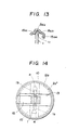
- Figs. 11 through 15 show a fourth embodiment of the invention.
- the fourth embodiment is arranged such that pivot portions lb and lb of a key body 1 is supported by a cap 2 through a separate support member and a resilient tongue.
- a pair of bearing sections 10 and 10 opposed to each other diametrically of the cap 2 are integrally formed on a bottom surface of a circular recess 2a' in the cap 2 in a fashion projected from the bottom surface, and the pivot portions lb and lb of the key body 1 are respectively fitted pivotally in diametrically opposed grooves 10a and 10a formed respectively in the bearing sections 10 and 10, through bushes 4 and 4.
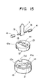
- a cylindrical support member 12 is fitted in the circular recess 2a' in the cap 2 with one circular open end face of the support member 12 abutting against an underside 2b' of a knob portion 2b (bottom surface of the recess 2a').
- the support member 12 has the other end face 12a forming a bottom wall in which an elongated opening 13 is formed substantially at a center of the bottom wall.
- the key body 1 has an insert portion la extending through the opening 13, and the pivot portions lb and lb are respectively supported in bearing recesses 14 and 14 in the support member 12 which are formed in an inner surface of the bottom wall 12a and respectively open at respective central portions of side edges of the opening 13.
- the pivot portions lb and lb of the key body 1 are respectively clamped pivotally between the bearing recesses 14 and 14 of the support member 12 and the bearing sections 10 and 10 of the cap 2 through the bushes 4 and 4 which are fitted on the pivot portions lb and lb, respectively.
- a resilient tongue 15 has one end thereof fixedly connected to an inner peripheral surface of the support member 12 by means of weld or the like and extends diametrically into the circular recess 2a' in the cap 2 to a position slightly beyond the diametrical center.
- the key body 1 has an inward end lc thereof which slidably and resiliently abuts against an outwardly facing concave surface 15a at the free end of the resilient tongue 15.
- the concave surface 15a is comprised of a vertical surface section 15a l facing to a side surface of the key body 1 toward the levelling direction thereof, a horizontal surface section 15a 2 formed adjacent the vertical surface section l5a l and extending toward the free end of the resilient tongue 15, an inclined surface section 15a3 extending obliquely outwardly, and a vertical surface section 15a4, which surface sections are continuous to each other.
- the side surface of the inward end lc and an end face of the inward end lc of the key body 1 simultaneously abut against the vertical surface section 15a 1 and the horizontal surface section 15a 2 , respectively, to thereby stably retain the key body 1 in a raised portion.
- the inward end lc slides along the inclined surface section 15a3 and, as the key body 1 reaches the levelled position where it is received within the cut-out 2d in the cap 2, the inward end lc abuts against the vertical surface section 15a4, to thereby stably retain the key body 1 in the levelled position.
- the fourth embodiment has the cut-out 2d provided in a rearward edge portion of the cap 2 corresponding to the rear of the vehicle, and can provide advantages similar to those discribed above.
- the fourth embodiment it is possible to reduce the thickness of the cap 2, and it would be possible to pivotally support the key body by the support member 12 and the resilient tongue 9 in a smooth manner for a long time without any hindrance to the levelling movement of the key body even if the support member 12 and the resilient tongue 9 are contaminated with dust.
Landscapes
- Lock And Its Accessories (AREA)
Applications Claiming Priority (4)
| Application Number | Priority Date | Filing Date | Title |
|---|---|---|---|
| JP196861/84U | 1984-12-28 | ||
| JP19686184U JPH0234374Y2 (de) | 1984-12-28 | 1984-12-28 | |
| JP23780/85U | 1985-02-20 | ||
| JP2378085U JPS625446U (de) | 1985-02-20 | 1985-02-20 |
Publications (3)
| Publication Number | Publication Date |
|---|---|
| EP0187101A2 true EP0187101A2 (de) | 1986-07-09 |
| EP0187101A3 EP0187101A3 (en) | 1987-05-20 |
| EP0187101B1 EP0187101B1 (de) | 1989-12-13 |
Family
ID=26361194
Family Applications (1)
| Application Number | Title | Priority Date | Filing Date |
|---|---|---|---|
| EP19850402599 Expired EP0187101B1 (de) | 1984-12-28 | 1985-12-23 | Zusammenklappbarer Schlüssel für Fahrzeuge |
Country Status (5)
| Country | Link |
|---|---|
| US (1) | US4637238A (de) |
| EP (1) | EP0187101B1 (de) |
| AU (1) | AU575456B2 (de) |
| CA (1) | CA1247394A (de) |
| DE (2) | DE3574750D1 (de) |
Cited By (2)
| Publication number | Priority date | Publication date | Assignee | Title |
|---|---|---|---|---|
| EP0874116A1 (de) * | 1997-04-23 | 1998-10-28 | SERRATURE MERONI S.p.A. | Zusammenklappbarer Schlüssel |
| DE102006008450A1 (de) * | 2006-02-23 | 2007-08-30 | Motorenfabrik Hatz Gmbh & Co. Kg | Startschalter |
Families Citing this family (14)
| Publication number | Priority date | Publication date | Assignee | Title |
|---|---|---|---|---|
| JPH02112861U (de) * | 1988-09-26 | 1990-09-10 | ||
| US5207082A (en) * | 1992-04-08 | 1993-05-04 | Lemaitre Thomas H | Key holding device |
| USD348774S (en) | 1993-05-05 | 1994-07-19 | Peter H. Sammond | Combined key-retainer and parking lot locator |
| US5440910A (en) * | 1993-06-07 | 1995-08-15 | Florian; David W. | Key adaptor |
| US6164102A (en) * | 1994-01-18 | 2000-12-26 | Gapco; Brian E. | Key handle |
| US6386121B1 (en) * | 1998-09-21 | 2002-05-14 | Alfred S. Aguilar | Safety deposit box locking system |
| US6598438B2 (en) * | 2001-04-11 | 2003-07-29 | Brendan Evans Ashby | Key wrench |
| FR2851783B1 (fr) * | 2003-02-28 | 2005-04-08 | Valeo Securite Habitacle Sas | Boitier de cle |
| FR2869934B1 (fr) * | 2004-05-04 | 2006-07-14 | Valeo Securite Habitacle Sas | Cle a insert escamotable comportant des moyens d'entrainement de l'insert |
| JP4694991B2 (ja) * | 2006-03-14 | 2011-06-08 | 株式会社東海理化電機製作所 | メカキー及び施解錠キー |
| US9060571B2 (en) * | 2012-04-25 | 2015-06-23 | Db Imports Inc. | Combined fashion accessory and key |
| FI126753B (fi) * | 2014-06-27 | 2017-05-15 | Abloy Oy | Riippulukko |
| US20160177597A1 (en) * | 2014-12-23 | 2016-06-23 | Mainetti S.P.A. | Anti-shoplifting device of the pin type |
| US11280579B2 (en) * | 2018-07-09 | 2022-03-22 | Peace KEYper, Inc. | Self-defense key holder |
Family Cites Families (8)
| Publication number | Priority date | Publication date | Assignee | Title |
|---|---|---|---|---|
| US3027606A (en) * | 1959-11-06 | 1962-04-03 | Catherine R Nicklas | Pivotal sliding closure |
| US3142508A (en) * | 1962-07-13 | 1964-07-28 | Vincent K Mchugh | Portable sun-glare visor |
| US3618346A (en) * | 1970-07-22 | 1971-11-09 | David H Humphrey | Key holder and key |
| FR2360728A1 (fr) * | 1976-08-02 | 1978-03-03 | Neiman Sa | Cle pliante a deux positions d'utilisation |
| US4325243A (en) * | 1978-09-08 | 1982-04-20 | Aisin Seiki Company, Limited | Key holder |
| FR2522941B1 (fr) * | 1982-03-09 | 1985-06-07 | Renault | Porte-clefs du type a clef escamotable dans un boitier |
| SE435640B (sv) * | 1982-09-16 | 1984-10-08 | Volvo Penta Ab | Anordning vid startlas for batar |
| JPH1112592A (ja) * | 1997-06-23 | 1999-01-19 | Kikkoman Corp | 油脂の安定化方法 |
-
1985
- 1985-12-23 US US06/812,292 patent/US4637238A/en not_active Expired - Fee Related
- 1985-12-23 DE DE8585402599T patent/DE3574750D1/de not_active Expired - Lifetime
- 1985-12-23 DE DE198585402599T patent/DE187101T1/de active Pending
- 1985-12-23 EP EP19850402599 patent/EP0187101B1/de not_active Expired
- 1985-12-24 AU AU51697/85A patent/AU575456B2/en not_active Ceased
- 1985-12-24 CA CA000498586A patent/CA1247394A/en not_active Expired
Cited By (3)
| Publication number | Priority date | Publication date | Assignee | Title |
|---|---|---|---|---|
| EP0874116A1 (de) * | 1997-04-23 | 1998-10-28 | SERRATURE MERONI S.p.A. | Zusammenklappbarer Schlüssel |
| US6035679A (en) * | 1997-04-23 | 2000-03-14 | Serrature Meroni S.P.A. | Hinged lock key |
| DE102006008450A1 (de) * | 2006-02-23 | 2007-08-30 | Motorenfabrik Hatz Gmbh & Co. Kg | Startschalter |
Also Published As
| Publication number | Publication date |
|---|---|
| AU5169785A (en) | 1986-07-03 |
| CA1247394A (en) | 1988-12-28 |
| US4637238A (en) | 1987-01-20 |
| EP0187101A3 (en) | 1987-05-20 |
| DE3574750D1 (de) | 1990-01-18 |
| DE187101T1 (de) | 1987-02-05 |
| EP0187101B1 (de) | 1989-12-13 |
| AU575456B2 (en) | 1988-07-28 |
Similar Documents
| Publication | Publication Date | Title |
|---|---|---|
| US4637238A (en) | Folding key for vehicles | |
| USD419786S (en) | Juvenile vehicle seat | |
| JPS6239781U (de) | ||
| JPS6328062U (de) | ||
| JPS61165283U (de) | ||
| JPH0393736U (de) | ||
| JPH05105140A (ja) | 自動二輪車のテールランプ装置 | |
| JPH055084Y2 (de) | ||
| JPH067986Y2 (ja) | 自動車用アウトサイドミラー | |
| KR0131035Y1 (ko) | 자동차의 컵홀더 | |
| JPH0298085U (de) | ||
| JPS5821662Y2 (ja) | 調理用具等における口金又は尻金の組付構造 | |
| JPS58135267U (ja) | 釣竿用リ−ルシ−ト | |
| JPS632061Y2 (de) | ||
| JPH0343043U (de) | ||
| JPH05310161A (ja) | 自動二輪車の後輪泥除け | |
| JPH0293808U (de) | ||
| JPH0426844U (de) | ||
| JPS5861631U (ja) | オ−トマチツク車用シフトレバ−装置 | |
| JPS6354595U (de) | ||
| JPS63147373U (de) | ||
| JPH0598852A (ja) | インサイドハンドル組付構造 | |
| JPS62122740U (de) | ||
| JPS5927943U (ja) | 自動車用アウトサイドミラ− | |
| JPS6264688U (de) |
Legal Events
| Date | Code | Title | Description |
|---|---|---|---|
| PUAI | Public reference made under article 153(3) epc to a published international application that has entered the european phase |
Free format text: ORIGINAL CODE: 0009012 |
|
| AK | Designated contracting states |
Kind code of ref document: A2 Designated state(s): DE FR GB |
|
| RAP1 | Party data changed (applicant data changed or rights of an application transferred) |
Owner name: HONDA LOCK MANUFACTURING CO., LTD. Owner name: HONDA GIKEN KOGYO KABUSHIKI KAISHA |
|
| EL | Fr: translation of claims filed | ||
| DET | De: translation of patent claims | ||
| PUAL | Search report despatched |
Free format text: ORIGINAL CODE: 0009013 |
|
| AK | Designated contracting states |
Kind code of ref document: A3 Designated state(s): DE FR GB |
|
| 17P | Request for examination filed |
Effective date: 19870914 |
|
| 17Q | First examination report despatched |
Effective date: 19880215 |
|
| RAP1 | Party data changed (applicant data changed or rights of an application transferred) |
Owner name: HONDA LOCK MANUFACTURING CO., LTD. Owner name: HONDA GIKEN KOGYO KABUSHIKI KAISHA |
|
| GRAA | (expected) grant |
Free format text: ORIGINAL CODE: 0009210 |
|
| AK | Designated contracting states |
Kind code of ref document: B1 Designated state(s): DE |
|
| REF | Corresponds to: |
Ref document number: 3574750 Country of ref document: DE Date of ref document: 19900118 |
|
| PLBE | No opposition filed within time limit |
Free format text: ORIGINAL CODE: 0009261 |
|
| STAA | Information on the status of an ep patent application or granted ep patent |
Free format text: STATUS: NO OPPOSITION FILED WITHIN TIME LIMIT |
|
| 26N | No opposition filed | ||
| PGFP | Annual fee paid to national office [announced via postgrant information from national office to epo] |
Ref country code: DE Payment date: 19970227 Year of fee payment: 12 |
|
| PG25 | Lapsed in a contracting state [announced via postgrant information from national office to epo] |
Ref country code: DE Free format text: LAPSE BECAUSE OF NON-PAYMENT OF DUE FEES Effective date: 19980901 |