EP0187024A2 - Tape-draw out mechanism - Google Patents
Tape-draw out mechanism Download PDFInfo
- Publication number
- EP0187024A2 EP0187024A2 EP85309245A EP85309245A EP0187024A2 EP 0187024 A2 EP0187024 A2 EP 0187024A2 EP 85309245 A EP85309245 A EP 85309245A EP 85309245 A EP85309245 A EP 85309245A EP 0187024 A2 EP0187024 A2 EP 0187024A2
- Authority
- EP
- European Patent Office
- Prior art keywords
- tape
- arm
- draw
- drawn
- initial position
- Prior art date
- Legal status (The legal status is an assumption and is not a legal conclusion. Google has not performed a legal analysis and makes no representation as to the accuracy of the status listed.)
- Granted
Links
- 230000033001 locomotion Effects 0.000 claims description 9
- 238000001816 cooling Methods 0.000 claims description 3
- 238000010586 diagram Methods 0.000 description 20
- 238000001514 detection method Methods 0.000 description 5
- 238000012840 feeding operation Methods 0.000 description 4
- 229920001971 elastomer Polymers 0.000 description 3
- 238000012986 modification Methods 0.000 description 3
- 230000004048 modification Effects 0.000 description 3
- 230000002035 prolonged effect Effects 0.000 description 3
- 239000005060 rubber Substances 0.000 description 3
- 238000004804 winding Methods 0.000 description 3
- 230000002411 adverse Effects 0.000 description 2
- 230000000694 effects Effects 0.000 description 2
- 230000005540 biological transmission Effects 0.000 description 1
- 230000015556 catabolic process Effects 0.000 description 1
- 238000007796 conventional method Methods 0.000 description 1
- 238000006731 degradation reaction Methods 0.000 description 1
- 238000012423 maintenance Methods 0.000 description 1
- 230000007257 malfunction Effects 0.000 description 1
- 238000003825 pressing Methods 0.000 description 1
- 238000012545 processing Methods 0.000 description 1
- 230000004043 responsiveness Effects 0.000 description 1
- 238000004904 shortening Methods 0.000 description 1
Images


Classifications
-
- G—PHYSICS
- G11—INFORMATION STORAGE
- G11B—INFORMATION STORAGE BASED ON RELATIVE MOVEMENT BETWEEN RECORD CARRIER AND TRANSDUCER
- G11B15/00—Driving, starting or stopping record carriers of filamentary or web form; Driving both such record carriers and heads; Guiding such record carriers or containers therefor; Control thereof; Control of operating function
- G11B15/60—Guiding record carrier
- G11B15/66—Threading; Loading; Automatic self-loading
- G11B15/665—Threading; Loading; Automatic self-loading by extracting loop of record carrier from container
-
- G—PHYSICS
- G11—INFORMATION STORAGE
- G11B—INFORMATION STORAGE BASED ON RELATIVE MOVEMENT BETWEEN RECORD CARRIER AND TRANSDUCER
- G11B33/00—Constructional parts, details or accessories not provided for in the other groups of this subclass
- G11B33/14—Reducing influence of physical parameters, e.g. temperature change, moisture, dust
-
- G—PHYSICS
- G11—INFORMATION STORAGE
- G11B—INFORMATION STORAGE BASED ON RELATIVE MOVEMENT BETWEEN RECORD CARRIER AND TRANSDUCER
- G11B15/00—Driving, starting or stopping record carriers of filamentary or web form; Driving both such record carriers and heads; Guiding such record carriers or containers therefor; Control thereof; Control of operating function
- G11B15/60—Guiding record carrier
- G11B15/66—Threading; Loading; Automatic self-loading
- G11B15/665—Threading; Loading; Automatic self-loading by extracting loop of record carrier from container
- G11B15/6651—Threading; Loading; Automatic self-loading by extracting loop of record carrier from container to pull the record carrier against non rotating heads
-
- G—PHYSICS
- G11—INFORMATION STORAGE
- G11B—INFORMATION STORAGE BASED ON RELATIVE MOVEMENT BETWEEN RECORD CARRIER AND TRANSDUCER
- G11B15/00—Driving, starting or stopping record carriers of filamentary or web form; Driving both such record carriers and heads; Guiding such record carriers or containers therefor; Control thereof; Control of operating function
- G11B15/675—Guiding containers, e.g. loading, ejecting cassettes
- G11B15/68—Automatic cassette changing arrangements; automatic tape changing arrangements
- G11B15/6805—Automatic cassette changing arrangements; automatic tape changing arrangements with linearly moving rectangular box shaped magazines
- G11B15/681—Automatic cassette changing arrangements; automatic tape changing arrangements with linearly moving rectangular box shaped magazines in vertical direction
-
- G—PHYSICS
- G11—INFORMATION STORAGE
- G11B—INFORMATION STORAGE BASED ON RELATIVE MOVEMENT BETWEEN RECORD CARRIER AND TRANSDUCER
- G11B25/00—Apparatus characterised by the shape of record carrier employed but not specific to the method of recording or reproducing, e.g. dictating apparatus; Combinations of such apparatus
- G11B25/06—Apparatus characterised by the shape of record carrier employed but not specific to the method of recording or reproducing, e.g. dictating apparatus; Combinations of such apparatus using web-form record carriers, e.g. tape
- G11B25/063—Apparatus characterised by the shape of record carrier employed but not specific to the method of recording or reproducing, e.g. dictating apparatus; Combinations of such apparatus using web-form record carriers, e.g. tape using tape inside container
Definitions
- driving means for reciprocating the tape draw-out member between the initial position and the tape drawn-out position is so constructed that the time required for returning the tape draw-out member is shorter than the time required for drawing-out of the tape by the draw-out member.
- the engaging roller 22a of the crank plate 20a is slid toward the tape roller 2a along the link groove lla of the arm 10a and is slid again in the direction opposite to the tape roller 2a to turn the arm 10a clockwise.
- the engaging roller 22b of the crank plate 20b is slid toward the tape roller 2b along the link groove llb of the arm 10b and is slid again in the direction opposite to the tape roller 2b to turn the arm 10b counterclockwise.
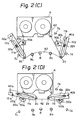
- the returned tape 62 is completely contained in the tape cartridge 6 and the tape surface becomes linear along the side face of the tape cartridge 6 [see Fig. 2-(A)], and,therefore, the tape 62 is not caught by some other member and the tape cartridge can be smoothly drawn out by the driving mechanism.
- the initial position is adjusted by the motor shafts 21a and 21b and the tape drawn-out position is adjusted by the stops 23a and 23b incorporated with the elastic member.
- the relatively soft rubbers (elastic members) 12a and 12b are deformed by the tape tension and the positions of the tape rollers 2a and 2b become unstable. Accordingly, this structure is not preferred. Therefore, the drawn-out position of the tape rollers 2a and 2b is preferably set by bringing relatively rigid engaging rollers 22a and 22b into contact with the link grooves lla and llb.
- a tape running path where the tape 62 is separated from the stationary guides 9a and 9b and the stationary magnetic head 8 is formed to prevent the recording surface of the tape from being damaged by high-speed contact of the tape 62 with the stationary guides 9a and 9b.
- FIG. 14 A practical example of the magnetic tape device 100 having the above-mentioned structure is illustrated in perspective views of Figs. 14 through 19.
- the magnetic tape device 100 comprises two magnetic tape device units 101 and 102 having the same structure, and each of the units 101 and 102 has the shutter 109 arranged in the top portion of the front face.
- the structure of the common frame 103 to which the magnetic tape device units 101 and 102 are attached is illustrated in Fig. 15..
- the power source 104 and cooling fan 105 used commonly for the units 101 and 102 are arranged in the lower portion of the common frame 103.
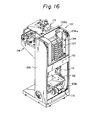
- the magnetic tape device unit 101 is illustrated in Fig. 16.
Landscapes
- Automatic Tape Cassette Changers (AREA)
- Adhesive Tape Dispensing Devices (AREA)
- Metal Extraction Processes (AREA)
- Registering, Tensioning, Guiding Webs, And Rollers Therefor (AREA)
Abstract
Description
- This invention relates to a tape draw-out mechanism for drawing out a tape from a tape cartridge or cassette such as a magnetic tape cartridge and forming a tape running path in which the tape is caused to abut against a stationary head. More particularly, the invention relates to a tape draw-out mechanism for drawing out a tape by driving a tape draw-out member.
- Magnetic tape devices are widely used for sound recording, picture recording, and data recording. In a magnetic tape device using a magnetic tape cartridge, especially a VTR tape cartridge, recording (writing) or reproduction (reading) is performed by drawing out a tape from the tape cartridge, forming a tape running path, and bringing the tape into contact with a stationary head. For this purpose, a tape draw-out mechanism is employed.
- The tape draw-out mechanism of a magnetic tape device known by the present inventor comprises a pair of tape draw-out members and motors for driving these members. When a tape cartridge is loaded on a driving mechanism of the magnetic tape device, a supply reel boss and a wind reel boss driven by a reel motor are engaged with the reels of the tape cartridge, and tape rollers arranged at the ends of arms constituting the tape draw-out members are introduced into the tape draw-out recesses of the tape cartridge. Then, the motors are rotated to turn the arms from an initial position to a drawn-out position, and by engagement of the tape with the tape rollers at the ends of the arms, the tape is drawn out from the tape cartridge and a tape running path for bringing the tape into contact with a stationary magnetic head and stationary guides is formed. After termination of recording/reproduction (reading/writing) by the stationary magnetic head, the motors are rotated in the reverse direction to return the arms to the initial position from the drawn-out position, whereby the tape is restored in the tape cartridge.
- In this tape draw-out mechanism, the tape draw-out time necessary for the draw-out members to move from the initial position to the tape drawn-out position depends on the speed of rotation of the arms, and this speed is set so that an excessive tension is not imposed on the tape when the tape is drawn out. The time required for the arms to move back to the initial position from the tape drawn-oput position is the same as the tape draw-out time, because the arms are rotated in the reverse direction at the same speed of rotation as described above. Therefore, when the tape is to be rewound by a fast rewind operation, an excessive amount of time elapses before the rewinding operation can be started after termination of recording or reproduction. Especially in a magnetic tape device of the type where recording and reproduction are continuously and automatically carried out, the time required for handling one cartridge is prolonged, and such wasted time accumulates and lowers the efficiency of operation of the device.
- It is an object of the present invention to provide a tape draw-out mechanism in which the time required for the return operation is shortened.
- According to one aspect of the invention there is provided a tape draw-out mechanism comprising a tape draw-out member to be engaged with a tape between a pair of reels; and tape draw-out member driving means for moving the tape draw-out member between an initial position and a tape drawn-out position; characterised in that the driving means is operable to move the tape draw-out member such that the return time required for returning the tape draw-out member to the initial position from the tape drawn-out position is shorter than the time required for moving the tape draw-out member to the tape drawn-out position from the initial position.
- According to another aspect of the invention there is provided a tape draw-out mechanism comprising a tape draw-out member to be engaged with a tape between a pair of reels; and tape draw-out member driving means for moving the' tape draw-out member between the initial position and a tape drawn-out position; characterised in the driving means is operable to move the tape draw-out member such that the return time required for returning the tape draw-out member to the initial position from the tape drawn-out position is shorter than the time required for moving the tape draw-out member to the tape drawn-out position from the initial position; in that the tape draw-out member comprises an arm having a tape engaging portion at one end and a fulcrum at the other end, the arm being turned by the driving means with the fulcrum as the centre of rotation; in that the arm has an elongate groove therein; and in that the driving means includes a crank member having one end engaged with the groove, the crank member being rotatable with a shaft thereof as the centre of rotation by a driving source, whereby rotation of the driving source is converted to a swinging motion of the arm.
- By use of the invention, when the tape is drawn out, the speed of movement of the tape draw-out member is restricted so that no excessive tension is imposed on the tape, but when the tape is returned, since the tension on the tape need not be taken into consideration, the speed of movement of the tape draw-out member is increased to shorten the return time. For this purpose, driving means for reciprocating the tape draw-out member between the initial position and the tape drawn-out position is so constructed that the time required for returning the tape draw-out member is shorter than the time required for drawing-out of the tape by the draw-out member.
- Embodiments of the invention will now be described, by way of example, with reference to the accompanying drawings, in which
- Fig. 1 is a diagram of the structure of one embodiment of the invention;
- Figs. '2A-2D are diagrams illustrating stages in the operation of the structure shown in Fig. 1;
- Figs. 3A and 3B are detailed diagrams showing the operation of the structure shown in Fig. 1;
- Fig. 4 is a diagram of the structure of another embodiment of the invention;
- Fig. 5 is a diagram to illustrate the operation of the structure shown in Fig. 4;
- Fig. 6 is a diagram of the structure of a further embodiment of the invention:
- Fig. 7 is a diagram illustrating the operation of the structure shown in Fig. 6;
- Figs. 8 and 9 are diagrams illustrating a quick-feeding operation in the embodiments of the present invention;
- Fig. 10 is a diagram of the structure of another embodiment of the invention;
- Fig. 11 is a diagram of a quick-feeding operation in the structure shown in Fig. 10;
- Fig. 12 is a perspective view of a magazine for containing therein tape cassettes to which the present invention is applied;
- Fig. 13 is a schematic diagram of a magnetic tape apparatus to which the invention is applied;
- Fig. 14 is a perspective view of a magnetic tape apparatus to which the invention is applied;
- Fig. 15 is a perspective view of a frame of the device shown in Fig. 14;
- Fig. 16 is a perspective view of a magnetic tape device which constitutes a part of the apparatus shown in Fig. 14;
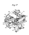
- Fig. 17 is a perspective view of a main part of the device shown in Fig. 16;
- Fig. 18 is a perspective view showing a front loading mechanism of the device shown in Fig. 16;
- Fig. 19 is a perspective view showing a push-back mechanism of the device shown in Fig. 16;
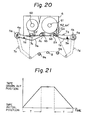
- Fig. 20 is a diagram of the structure of a prior tape draw-out mechanism of the related art; and
- Fig. 21 is a diagram illustrating a problem arising in the structure shown in Fig. 20.
- Before describing the present invention, an explanation of the prior art will be given with reference to Fig. 20.
- The tape draw-out mechanism of the magnetic tape device shown in Fig. 20 comprises a pair of tape draw-out
members 3a and 3b andmotors members 3a and 3b. A magnetic tape cartridge, or tape cassette, 6 comprises a pair ofreels magnetic tape 62 movable between thereels guides recesses tape cartridge 6 is loaded on a driving mechanism of a magnetic tape device, a supply reel boss and a take-up reel boss driven by a reel motor (not shown) are introduced into thereels tape cartridge 6, andtape rollers members 3a and 3b, are introduced into tape draw-outrecesses tape cartridge 6. Themotors axes tape 62 with thetape rollers tape 62 is drawn out from thetape cartridge 6 and a tape running path for bringing thetape 62 into contact with a stationarymagnetic head 8 andstationary guides magnetic head 8, themotors tape 62 is restored in thetape cartridge 6.Sensors sensors - Referring to Fig. 21, the tape draw-out time T necessary for the
members 3a and 3b of the above-described mechanism to move from the initial position to the tape drawn-out position depends on the speed of rotation of the arms la and lb, and this speed is set so that an excessive tension is not imposed on thetape 62 when thetape 62 is drawn out. The return time required for the arms la and Ib to move back to the initial position from the tape drawn-out position is the same as the time T above, because the arms la and lb are reversely rotated at the same speed as described above. Therefore, when the tape is to be rewound by a fast rewind operation, an excessive time is required before the rewinding operation can be started after the termination of recording to reproduction by the stationarymagnetic head 8. Especially in a magnetic tape device of the type where recording and reproduction are continuously and automatically carried out, the time required for handling each cartridge is prolonged, and such wasted time accumulates and lowers the efficiency of operation of the device. - Figure 1 is a diagram of the structure of one embodiment of the present invention. The same members as those shown in Fig. 20 are indicated by the same reference numerals. In Fig. 1,
tape rollers arms fulcra Crank plates rollers shafts shafts crank plates - Accordingly, the
arms motors crank plates rollers crank plates arms fulcra - The operation of the structure of the embodiment shown in Fig. 1 will now be described with reference to the operation diagram of Fig. 2.
- When the
tape cartridge 6 is loaded on the driving mechanism, as shown in Fig. 2-(A), thetape rollers arms recesses tape cartridge 6, and thetape 62 of thetape cartridge 6 is spread between theguides tape cartridge 6. The position of thearms - Then, as shown in Fig. 2-(B), the
motor 50a is rotated clockwise and themotor 50b is rotated counterclockwise. The clockwise rotation of themotor 50a causes thecrank plate 20a to be rotated clockwise and the engagingroller 22a on the top end of thecrank plate 20a is thus slid to the right in the drawings along the link groove lla of thearm 10a, whereby thearm 10a is turned clockwise with thefulcrum 40a as the center of rotation and thetape 62 is drawn out by thetape roller 2a on the top end of thearm 10a. Similarly, the counterclockwise rotation of themotor 50b causes thecrank plate 20b to be rotated counterclockwise and the engagingroller 22b on the top end of thecrank plate 20b is thus slid to the left in the drawings along the link groove llb of thearm 10b, whereby thearm 10b is rotated counterclockwise with thefulcrum 40b as the center of rotation and thetape 62 is drawn out by thetape roller 2b on the top end of thearm 10b. - Accordingly, when the
motor 50a is rotated clockwise and themotor 50b is rotated counterclockwise, the engagingroller 22a of thecrank plate 20a is slid toward thetape roller 2a along the link groove lla of thearm 10a and is slid again in the direction opposite to thetape roller 2a to turn thearm 10a clockwise. Similarly, the engagingroller 22b of thecrank plate 20b is slid toward thetape roller 2b along the link groove llb of thearm 10b and is slid again in the direction opposite to thetape roller 2b to turn thearm 10b counterclockwise. - When the
arms position detecting sensors sensors motors tape 62 comes into contact with the stationarymagnetic head 8 through thestationary guides motors arms - To return the
tape 62 after a read/write operation of thetape 62 by the stationary magnetic head, themotor 50a is rotated clockwise as in the draw-out operation and themotor 50b is rotated counterclockwise whereby, as shown in Fig. 2-(D), thecrank plate 20a is rotated clockwise and the engagingroller 22a on the top end of thecrank plate 20a is slid toward thefulcrum 40a along the link groove lla of thearm 10a to turn thearm 10a counterclockwise. Similarly, thecrank plate 20b is rotated counterclockwise and the engagingroller 22b on the top end of thecrank plate 20b is slid toward thefulcrum 40b along thelink groove 11b of thearm 10b to turn thearm 10b clockwise. - Thus, when the
motor 50a is rotated clockwise and themotor 50b is rotated counterclockwise, the engagingroller 22a of thecrank plate 20a is slid toward thefulcrum 40a along the link groove lla of thearm 10a and then reversely slid toward thetape roller 2a to further turn thearm 10a counterclockwise, while the engagingroller 22b of thecrank plate 20b is slid toward thefulcrum 40b along the link groove llb of thearm 10b and then reversely slid toward thetape roller 2b to further turn thearm 10b clockwise. When thearms position detecting sensors sensors motors tape 62 is completed. The quantity of rotation of themotors arms - If the positions of the
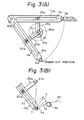
fulcra arms shafts crank plates rotation angle 61 for the draw-out operation is larger than therotation angle 62 for the return operation as shown in Fig. 3-(A), the rotation speed of thearms 10a and lOb for the return operation can be made higher than the rotation speed of thearms - Furthermore, if the position of the
fulcrum 40a (40b) is set so that at the initial position and drawn-out position, the longitudinal direction of the link groove lla (llb) of thearm 10a (10b) is orthogonal to the longitudinal direction of thecrank plate 20a (20b) as shown in Fig. 3-(A), thearm 10a (lOb) is reciprocated only between the initial position and the tape drawn-out position, i.e., the movable range of the arm is defined by the initial position and the drawn-out position. In this case, the relationship θ1 = 262 is established between θ1 and 62, and the return time may be reduced to about 1/2 of the draw-out time. - If the above-mentioned orthogonal relationship is maintained at the tape drawn-out position, as shown in Fig. 3-(B), when tape tension is applied to the
tape roller 2a (2b) by thetape 62, the direction of the component Tl of this tape tension is in agreement with the longitudinal direction of thearm 10a and is orthogonal to the longitudinal direction of thecrank plate 20a. Accordingly, no rotating force is imparted to the crankplate 20a (20b). Furthermore, since the direction of the other component T2 of the tape tension is in agreement with the longitudinal direction of thecrank plate 20a (20b), a rotating force cannot be imparted to the crankplate 20a (20b). Accordingly, since thecrank plate 20a (20b) is not rotated by the tape tension of thetape 62, the tape drawn-out position can be stably maintained. - Similarly, since the orthogonal relationship is maintained also'at the initial position, even if an external force is applied to the
arm cartridge 6, the initial position can be stably maintained. Accordingly, maintenance of the arm position by the crank mechanism becomes possible, and hence, a motor having a large torque against rotation by the outer force is not needed for maintaining the arm position. - Moreover, since the return operation can be accomplished even without reverse rotation of the
motors motors - Another embodiment of the present invention will now be described.
- Figure 4 is a diagram of a main part of the structure of this embodiment, wherein only the tape draw-out mechanism is shown. The same members as in Fig. 1 are represented by the same reference numerals. In Fig. 4, reference numeral lla' represents a link groove. The link groove lla' is formed in a shape such that arcuate portions c and c' having a radius corresponding to the length of the
crank plate 20a are formed along a predetermined length from the position where the longitudinal direction of thecrank plate 20a is orthogonal to the longitudinal direction of thearm 10a (the position of the engagingroller 22a in Fig. 4). The reason for this special shape of the link groove lla' is as follows. - Positioning of the
arm 10a at the tape drawn-out position is accomplished by stopping the rotation of themotor 50a driving thecrank plate 20a through a detection signal for thearm 10a emitted by thesensor 7c. Where the link groove lla is linear as in the first embodiment, if the drivingmotor 50a overruns the stop position, the position of thearm 10a is changed at the time of drawing out the tape. In this case, the contact angle of thetape 62 to thestationary guides tape 62 to thestationary guides tape 62 are changed and it is feared that an adverse influence will be imposed on the recording and reproduction characteristics. - Also, positioning of the
arm 10a at the initial position when returning the tape is accomplished by stopping the rotation of themotor 50a driving thecrank plate 20a by a detection signal for thearm 10a emitted by thesensor 7a. In this case, if the drivingmotor 50a should overrun beyond the stop position, thetape 62 does not completely enter thetape cartridge 6, and when the tape cartridge is withdrawn from by the driving mechanism, it is apprehended that the tape will be caught in some other part of the device and it will become impossible to withdraw thetape cartridge 6. - To avoid this disadvantage, in this embodiment, the link groove is not made linear but is formed to have arcuate portions c and c' as shown in Fig. 4, and the length of the arcuate portions is set according to the angle of estimated overrunning at the time of stopping the motor.
- The link groove of the
arm 10b is formed to have a similar shape. - The operation of the structure of the embodiment shown in Fig. 4 will now be described with reference to the operation diagram of Fig. 5. Positioning of the
tape 62 taken out from thetape cartridge 6 by thearms motors arms sensors crank plates arms motors rollers crank plates link grooves 11a' and llb' and do not rotate thearms tape rollers arms tape 62 are not changed but are precisely positioned at a predetermined point. Accordingly, a high-precision tape running path can be formed and a stable vibration absorbing characteristic of the tape between thestationary guides - Stopping of the
arms motors crank plates arms sensors motors rollers crank plates link grooves 11a' and llb' and do not rotate thearms arms tape 62 is completely contained in thetape cartridge 6 and the tape surface becomes linear along the side face of the tape cartridge 6 [see Fig. 2-(A)], and,therefore, thetape 62 is not caught by some other member and the tape cartridge can be smoothly drawn out by the driving mechanism. - As is apparent from the foregoing description, in the present embodiment, even if overrunning of the motor occurs, the initial position and tape drawn-out position remain constant and are not changed. Accordingly, a tape running path having a high positional precision can be formed, the recording and reproduction characteristics can be improved, and the tape cartridge can be smoothly drawn out.
- Still another embodiment of the present invention will now be described.
- Figures 6 and 7 are diagrams of the structure of a main part of still another embodiment of the present invention, wherein only the tape draw-out mechanism is shown. In Figs. 6 and 7, the same members as shown in Fig. 1 are indicated by the same reference numerals. In the figures, each
reference numeral elastic members elastic members Stops arms - The reason for adoption of this structure will now be described.
- As pointed out hereinbefore, if the initial position of the
tape rollers arms tape cartridge 6 is attached by the cartridge attaching mechanism to the supply reel boss and take-up reel boss, thetape rollers tape cartridge 6, and it is feared that a proper attachment will not be attained. Furthermore, in this case, thetape rollers tape 62 and there is a risk of damage to the tape, - Furthermore, if the
tape rollers arms tape 62 relative to thetape rollers stationary guides guides tape cartridge 6 are changed to change the frictional forces between the tape and these guides, and,therefore, it is feared that an adverse influence will be imposed on the recording and reproduction characteristics. - Since the two positions of the
tape rollers fulcra arms shafts - According to the present embodiment of the invention, this problem is solved in the following manner. Namely, the
elastic members plates stops arms elastic members tape rollers tape rollers stops - More specifically, the initial position is settled, as shown in Fig. 7, by abutting the
arms stops rollers elastic members tape rollers rollers tape rollers motors shafts crank plates - There may be considered a structure in which the initial position is adjusted by the
motor shafts stops tape rollers tape rollers tape rollers tape rollers engaging rollers tape 62 does come into contact with thetape rollers tape rollers - According to the embodiment having the above-mentioned structure, the adjustment of the positions of the
tape rollers - The operation of quick tape feeding of the read/write device having the above-mentioned tape draw-out structure will now be described.
- Figures 8 and 9 are diagrams illustrating the quick feeding operation by the tape draw-out mechanism of the present invention. In Figs. 8 and 9, the same members as in Fig. 1 are represented by the same reference numerals.
- According to the conventional technique, for quick feeding of the
tape 62 drawn out from thetape cartridge 6, as shown in Fig. 2-(B) or 2-(D), a tape running path where thetape 62 is separated from thestationary guides magnetic head 8 is formed to prevent the recording surface of the tape from being damaged by high-speed contact of thetape 62 with thestationary guides - This tape running path is formed by placing the drawn-out
tape 62 in contact with at least two tape guides (tape rollers) 2a and 2b outside thetape cartridge 6. The upper and lower ends of the tape guides 2a and 2b are flanged to guide thetape 62, and gaps in the height direction are necessary for rotatably attaching thearms fulcra arms tape guides tape 62 are readily damaged by the flanges of the tape guides 2a and 2b due to the difference in height between the two guides. - In order to obviate this disadvantage, in the present embodiment, the tape drawn out from the tape cartridge is brought into contact with only one tape guide outside the tape cartridge, whereby damage to the tape is reduced.
- Referring to Fig. 8, when the recording-reproduction operation (read/write operation) shown in Fig. 2-(C) is changed to the quick feeding operation, the
left arm 10a in Fig. 8 is driven to restore the initial position but theright arm 10b in Fig. 8 is not driven. Accordingly, theright tape guide 2b is not moved, and the tape running path formed by thetape guide 2b and thetape 62 is separated from thestationary guides magnetic head 8, as shown in Fig. 8. - The frequency of contact of the
tape 62 with the tape guide outside thetape cartridge 6 is thus reduced by one, and thus damage to thetape 62 is reduced. Especially when the flanged tape guides are used, thetape 62 is brought into contact with only one tape guide (only thetape guide 2b), and the distance between thistape guide 2b and the tape guides in the tape cartridge is prolonged. Therefore, even if there is a difference in height among a plurality of tape guides 2b, 63, and 64, damage to the edges of thetape 62 by the flange of thetape guide 2b can be reduced (from the experimental results, it was confirmed that a tape having a life of 1000 passes in the conventional structure can endure 2000 passes without trouble). - Furthermore, there may be adopted a modification in which, as shown in Fig. 9, the
right arm 10b in the drawings is slightly returned toward the initial position from the tape drawn-out position. Also, theleft arm 10a need not be returned to the initial position but it is sufficient if theleft arm 10a is returned to the point where it does not come into contact with thetape 62. - Still another embodiment of the present invention will now be described.
- Figure 10 is a diagram of still another embodiment of the present invention. In Fig. 10, the same members as shown in Fig. 1 are represented by the same reference numerals. In the figure, the
tape roller 2b is mounted on arotary arm 13 and thearm 13 can rotate relative to thearm 10b with thefulcrum 15a as the center of rotation. Aspring 14 is disposed to urge therotary arm 13 counterclockwise with thefulcrum 15a as the center of rotation, and a potentiometer (angle detector) 15 is arranged at thefulcrum 15a to detect the rotation angle of therotary arm 13. Namely, a detecting mechanism for detecting the tape tension imposed on thetape roller 2b is arranged on thearm 10b. - The operation of this embodiment will now be described. At the tape drawn out position indicated by a solid line in Fig. 10, the tape tension given to the
tape roller 2b is proportional to the rotation angle of the rotary arm and this is detected by thepotentiometer 15 to change the delivery speed of the reel motor and keep the tape tension constant. - At the time of quick feeding, as described above with reference to Fig. 8, only the arm l0a is returned to the position indicated by dash line in Fig. 10, and the
arm 10b is not moved. - Accordingly, the position of the
tape roller 2b at the time of quick feeding is not changed from its position at the time of recording and reproduction. Therefore, the angle B' between thetape 62 and thetape guide 2b at the time of quick feeding is almost the same as the angle A between thetape 62 and thetape guide 2b at the time of recording and reproduction, and the tape tension is not substantially changed. Also, the direction of the tape tension is prearranged so that the tape tension direction C at the time of recording and reproduction (tape angle is A) is parallel to the tangential direction D of the rotary movement of thearm 13, i.e., perpendicular to thearm 13 to obtain a maximum responsiveness of thearm 13 with respect to the tape tension. The tape tension direction C' at the time of quick feeding (tape angle is B') is almost the same as the direction C. Accordingly, the detection ability of the tape tension detecting device at the time of quick feeding is not substantially different from that at the time of recording and reproduction, and a tape running path in which the tape tension is stable can be obtained. - As shown in Fig. 11, if the arm llb is first returned slightly as indicated by a dash line and quick feeding is then carried out, since the angle A (Fig. 10) between the
tape 62 and the tape guide 6b at the time of recording and reproduction is smaller than the angle B between thetape 62 and the tape guide 6b at the time of quick feeding, the tape tension imposed on the tape tension detecting mechanism at the quick feeding angle B is reduced. Also, the tape tension direction C" (tape angle is B) at the time of quick feeding is deviated from the tangential direction D' of the rotary movement of thearm 13 at the position of quick feeding. Therefore, a minute change of the tension cannot be easily detected, and therefore, a problem of degradation of the tape tension detecting ability arises. - Accordingly, in the present embodiment, by making the position of the
arm 10b at the time of quick feeding equal to the position of thearm 10b at the time of recording and reproduction, the above-mentioned difference of the angle is eliminated and the detection of a minute change of the tape tension is made possible, whereby stable control of the tape tension is made possible even at the time of quick feeding. - Various modifications may be made to the foregoing embodiments without departing from the scope of the present invention, and these modifications are included in the scope of the present invention.
- As is apparent from the foregoing description, according to the present invention, a tape drawn-out member to be engaged with a tape between a pair of reels is disposed and a driving means is arranged for reciprocating the tape draw-out member between the initial position and the tape drawn-out position and driving the tape draw-out member so that the return time required for returning the tape draw-out member to the initial position from the tape drawn-out position is shorter than the draw-out time for-moving the draw-out member to the tape drawn-out position from the initial position, and drawing-out and return of the tape are accomplished by the reciprocating movement of the tape draw-out member. By dint of these characteristic features, there can be attained an effect of shortening the time required for returning the tape draw-out member to the initial position from the tape drawn-out position, whereby the time required for handling one cartridge (cassette) can be shortened and the mechanism of the present invention makes a contribution to the enhancement of the capacity of the magnetic tape device. Moreover, there can be attained a practical effect of realizing the above improvement by a simple structure.
- A cassette type magnetic tape device provided with the tape draw-out mechanism of the present invention will now be described.
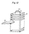
- A magnetic disc device is used as read-out means capable of storing much information in a high density and promptly accessible to optional information positions. In this magnetic disc device, there is a risk that data will be lost by accidental head crush or the like. Accordingly, to maintain the safety of data, it is preferred that data in a magnetic disc be once transferred to a magnetic tape and stored therein. In this case, the magnetic tape is contained in a cassette 133 (same as the
cassette 6 in the foregoing embodiments), as shown in Fig. 12, and these cassettes are contained in a plurality of stages horizontally in a magazine (cassette holder) as indicated by arrow C. A handle 134 foldable in the direction indicated by arrow B is arranaged in the top portion of themagazine 107 to facilitate the transportation of themagazine 107 or attachment or dismounting of themagazine 107 to or from the magnetic tape device. - An embodiment of the magnetic tape device in which this
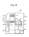
cassette magazine 107 is contained is illustrated in Fig. 13. As described hereinafter, two magnetic tape device units 101 (one is shown in Fig. 13) are attached to acommon frame 103 in themagnetic tape device 100. The magnetictape device unit 101 comprises a supportingstand 137 for loading and holding themagazine 107 thereon, alift mechanism 136 for vertically moving the supportingstand 137, read/write means 114 including themagnetic head 138, a windingmotor 122, and a tape draw-outmechanism 137 as described hereinbefore, afront loading mechanism 116 for automatically attaching acassette 133 to the read/write means 114, a cassette push-outmechanism 135 including amember 110 which confronts an inlet of thefront loading mechanism 116 and can be reciprocated as indicated by an arrow D to push out thecassette 133 contained in the magazine and push thecassette 133 into thefront loading mechanism 116, a push-return mechanism 115 including a push-return member 132 for pushing the returning the cassette which has returned to the inlet of the front loading mechanism after the read/write operation, into themagazine 107, and an openable andclosable shutter 109 for covering amagazine charging opening 139. Apower source 104 and a coolingfan 105 are attached to thecommon frame 103. - A practical example of the
magnetic tape device 100 having the above-mentioned structure is illustrated in perspective views of Figs. 14 through 19. As shown in Fig. 14, themagnetic tape device 100 comprises two magnetictape device units units shutter 109 arranged in the top portion of the front face. The structure of thecommon frame 103 to which the magnetictape device units power source 104 and coolingfan 105 used commonly for theunits common frame 103. The magnetictape device unit 101 is illustrated in Fig. 16. Four pulleys 108 (three pulleys 108a through 108c are seen in the drawing) are formed on the four corners of aside frame 106, respectively, and an endless belt (not shown) is engaged with these pulleys. The above-mentioned shutter 109 (see Figs. 13 and 14) is attached to the endless belt, and one pulley is rotated and driven by a motor (not shown) to open or close theshutter 109. Initially, themagazine 107 is arranged in the upper portion of theunit 101 as shown in the drawings, and cassettes are treated in sequence from the cassette in the lowermost stage and when the treatment of one cassette is completed, the magazine is brought down (as indicated by arrow E in Fig. 13) by one stage by the lift mechanism 136 (see Fig. 13) and the subsequent cassette is treated. For example, thelift mechanism 136 comprises a spiral cam which rises by one stage at each one rotation, and the vertical movement of the magazine may be performed by a cam follower arranged on the supporting stand having themagazine 107 loaded thereon. A rack-pinion mechanism, an endless chain mechanism, or other appropriate moving mechanism may be used for thelift mechanism 136. The push-outmember 110 of the push-out mechanism 135 (see Fig. 13) has an L-shape as shown in Fig. 16, and one end of the L-shape is secured to arotary shaft 111 and is rotated and reciprocated as indicated by arrow J. Therotary shaft 111 is connected to amotor 113 through arotation transmission mechanism 112 and driven by themotor 113. By the rotary movement of the L-shaped push-outmember 110 in the magazine, the cassette 133 (see Fig. 13) in themagazine 107 is pushed into the inside of theunit 101. The read/write means 114 shown in Fig. 17, is arranged on the back face of the magnetictape device unit 101, and the read/write means 114 comprises amagnetic head 138, astationary tape guide 115,tape reel motors tape roller 125 corresponds to thetape rollers swing shaft 126 of thetape roller 125 corresponds to therotation shafts arms tension sensor 124 corresponds to thetension sensor 15 in the embodiment shown in Fig. 10. As shown in Fig. 18, thefront loading mechanism 116 for setting the cassette at the read/write means has acassette inserting opening 117 from which the cassette is horizontally inserted from the front. When the cassette is thus inserted, adisc 119 is rotated as indicated by arrow K to rotate and move agrooved link 120. Apin 121 connected to a cassette loading stand (not shown) is engaged with the groove of thegrooved link 120 to move the cassette loading stand along an L-shapedguide groove 118. Accordingly, as shown in Fig. 13, the cassette is first moved in the horizontal direction as indicated by arrow F and then the cassette is brought down as indicated by arrow G and placed on thereel motors front loading mechanism 116. Thedisc 128 is rotated with theshaft 129 as the center of rotation by themotor 127. Agrooved arm 130 connected to thisdisc 128 moves apin 131 linearly in the groove. Apush roller 132 is connected to thispin 131 and is moved in the direction of arrow H to push-return the cassette into the magazine 107 (see Fig. 13) after the treatment. By repeating the above operations, the cassettes are automatically delivered and returned in sequence from the lowermost cassette, and, for example, the processing of transferring and writing data from a magnetic disc as described above is continuously carried out.
Claims (15)
Applications Claiming Priority (2)
| Application Number | Priority Date | Filing Date | Title |
|---|---|---|---|
| JP269893/84 | 1984-12-21 | ||
| JP59269893A JPS61148660A (en) | 1984-12-21 | 1984-12-21 | Tape drawing mechanism |
Publications (3)
| Publication Number | Publication Date |
|---|---|
| EP0187024A2 true EP0187024A2 (en) | 1986-07-09 |
| EP0187024A3 EP0187024A3 (en) | 1988-04-20 |
| EP0187024B1 EP0187024B1 (en) | 1991-06-05 |
Family
ID=17478682
Family Applications (1)
| Application Number | Title | Priority Date | Filing Date |
|---|---|---|---|
| EP85309245A Expired - Lifetime EP0187024B1 (en) | 1984-12-21 | 1985-12-18 | Tape-draw out mechanism |
Country Status (8)
| Country | Link |
|---|---|
| US (1) | US4697215A (en) |
| EP (1) | EP0187024B1 (en) |
| JP (1) | JPS61148660A (en) |
| KR (1) | KR900003569B1 (en) |
| AU (1) | AU555211B2 (en) |
| CA (1) | CA1271177A (en) |
| DE (1) | DE3583129D1 (en) |
| ES (1) | ES8704846A1 (en) |
Cited By (3)
| Publication number | Priority date | Publication date | Assignee | Title |
|---|---|---|---|---|
| EP0238752A1 (en) * | 1986-01-25 | 1987-09-30 | Hewlett-Packard Limited | Magazine for data storage units in combination with read/write apparatus for receiving the magazine |
| EP0494245A1 (en) * | 1989-09-29 | 1992-07-15 | Storage Technology Corp | Autoloader magazine for tape cartridges and method therefor. |
| WO1994003893A1 (en) * | 1992-08-03 | 1994-02-17 | Kah On Koo | Cassette tape extraction and drive apparatus and method |
Families Citing this family (13)
| Publication number | Priority date | Publication date | Assignee | Title |
|---|---|---|---|---|
| JPH07111801B2 (en) * | 1987-02-10 | 1995-11-29 | 株式会社日立製作所 | Recording / playback device |
| US5041929A (en) * | 1989-09-29 | 1991-08-20 | Storage Technology Corporation | Autoloader for magnetic tape cartridges |
| US5050020A (en) * | 1989-11-09 | 1991-09-17 | Archive Corporation | Cartridge loader for loading each of a plurality of cartridges into a cartridge insertion slot |
| US5182687A (en) * | 1989-11-09 | 1993-01-26 | Archive Corporation | Method and apparatus for aligning cartridges with a cartridge insertion slot |
| US5045958A (en) * | 1990-03-05 | 1991-09-03 | Storage Technology Corporation | Positioner for magnetic tape cartridge magazine |
| US5182686A (en) * | 1990-04-04 | 1993-01-26 | Universities Research Association, Inc. | Apparatus and method for loading and unloading multiple digital tape cassettes utilizing a removable magazine |
| US5231552A (en) * | 1990-06-29 | 1993-07-27 | Digital Equipment Corporation | Magazine and receiver for media cartridge loader |
| US5581423A (en) * | 1991-06-24 | 1996-12-03 | Seiko Epson Corporation | Disk driving motor and chcuking mechanism for disk drive apparatus |
| US5648881A (en) * | 1991-06-24 | 1997-07-15 | Seiko Epson Corporation | Disk driving motor and chucking mechanism for disk drive apparatus |
| US5264974A (en) * | 1991-09-30 | 1993-11-23 | Campbell Kenneth C | Cassette loading system |
| US5285333A (en) * | 1991-12-27 | 1994-02-08 | Archive Corporation | Mass storage and retrieval system for magnetic tape cartridges |
| KR0176580B1 (en) * | 1996-03-29 | 1999-04-15 | 김광호 | Pole base transferring device for a tape recorder |
| US9784648B2 (en) | 2010-09-07 | 2017-10-10 | President And Fellows Of Harvard College | Methods, apparatuses and systems for collection of tissue sections |
Citations (8)
| Publication number | Priority date | Publication date | Assignee | Title |
|---|---|---|---|---|
| US496964A (en) * | 1893-05-09 | Ornamented paper | ||
| US3453397A (en) * | 1963-09-19 | 1969-07-01 | Cart Trac Inc | Shiftable magazine sound tape cartridge apparatus |
| US3504916A (en) * | 1967-12-22 | 1970-04-07 | Itsuki Ban | Automatic playing apparatus |
| US3650413A (en) * | 1964-08-12 | 1972-03-21 | Sarkes Tarzian | Automatic tape cartridge changing mechanism |
| USB496964I5 (en) * | 1971-01-04 | 1976-04-20 | ||
| DE2534508B2 (en) * | 1974-08-05 | 1977-09-08 | Staar S A, Brüssel | DEVICE FOR INDEPENDENTLY CREATING AND GUIDING A MAGNETIC TAPE AROUND THE GUIDE DRUM IN A DEVICE FOR MAGNETIC RECORDING AND / OR REPLAY |
| EP0028928A1 (en) * | 1979-11-08 | 1981-05-20 | Matsushita Electric Industrial Co., Ltd. | A magnetic tape recording and/or reproducing apparatus |
| DE3230001A1 (en) * | 1981-08-13 | 1983-03-03 | Victor Company Of Japan, Ltd., Yokohama, Kanagawa | VIDEO SIGNAL RECORDING AND PLAYING DEVICE |
Family Cites Families (3)
| Publication number | Priority date | Publication date | Assignee | Title |
|---|---|---|---|---|
| NL188771C (en) * | 1982-03-11 | 1992-09-16 | Philips Nv | MAGNETIC TAPE CASSETTE, AND A SYSTEM INCLUDING THE MAGNETIC TAPE CASSETTE AND A MAGNETIC TAPE CASSETTE DEVICE. |
| JPH0245254B2 (en) * | 1983-08-29 | 1990-10-08 | Fujitsu Ltd | TEEPUHIKIDASHIKIKO |
| JPS6050652A (en) * | 1983-08-29 | 1985-03-20 | Fujitsu Ltd | Pull-out means of tape |
-
1984
- 1984-12-21 JP JP59269893A patent/JPS61148660A/en active Granted
-
1985
- 1985-12-17 CA CA000497907A patent/CA1271177A/en not_active Expired - Lifetime
- 1985-12-18 EP EP85309245A patent/EP0187024B1/en not_active Expired - Lifetime
- 1985-12-18 DE DE8585309245T patent/DE3583129D1/en not_active Expired - Fee Related
- 1985-12-19 AU AU51462/85A patent/AU555211B2/en not_active Ceased
- 1985-12-19 US US06/810,634 patent/US4697215A/en not_active Expired - Fee Related
- 1985-12-20 ES ES550257A patent/ES8704846A1/en not_active Expired
- 1985-12-21 KR KR1019850009693A patent/KR900003569B1/en not_active IP Right Cessation
Patent Citations (8)
| Publication number | Priority date | Publication date | Assignee | Title |
|---|---|---|---|---|
| US496964A (en) * | 1893-05-09 | Ornamented paper | ||
| US3453397A (en) * | 1963-09-19 | 1969-07-01 | Cart Trac Inc | Shiftable magazine sound tape cartridge apparatus |
| US3650413A (en) * | 1964-08-12 | 1972-03-21 | Sarkes Tarzian | Automatic tape cartridge changing mechanism |
| US3504916A (en) * | 1967-12-22 | 1970-04-07 | Itsuki Ban | Automatic playing apparatus |
| USB496964I5 (en) * | 1971-01-04 | 1976-04-20 | ||
| DE2534508B2 (en) * | 1974-08-05 | 1977-09-08 | Staar S A, Brüssel | DEVICE FOR INDEPENDENTLY CREATING AND GUIDING A MAGNETIC TAPE AROUND THE GUIDE DRUM IN A DEVICE FOR MAGNETIC RECORDING AND / OR REPLAY |
| EP0028928A1 (en) * | 1979-11-08 | 1981-05-20 | Matsushita Electric Industrial Co., Ltd. | A magnetic tape recording and/or reproducing apparatus |
| DE3230001A1 (en) * | 1981-08-13 | 1983-03-03 | Victor Company Of Japan, Ltd., Yokohama, Kanagawa | VIDEO SIGNAL RECORDING AND PLAYING DEVICE |
Cited By (5)
| Publication number | Priority date | Publication date | Assignee | Title |
|---|---|---|---|---|
| EP0238752A1 (en) * | 1986-01-25 | 1987-09-30 | Hewlett-Packard Limited | Magazine for data storage units in combination with read/write apparatus for receiving the magazine |
| EP0494245A1 (en) * | 1989-09-29 | 1992-07-15 | Storage Technology Corp | Autoloader magazine for tape cartridges and method therefor. |
| EP0494245A4 (en) * | 1989-09-29 | 1993-03-31 | Storage Technology Corporation | Autoloader magazine for tape cartridges and method therefor |
| WO1994003893A1 (en) * | 1992-08-03 | 1994-02-17 | Kah On Koo | Cassette tape extraction and drive apparatus and method |
| US5430586A (en) * | 1992-08-03 | 1995-07-04 | Koo; Kah O. | Tape extractor and pad lifter for extracting tape from a cassette center well, and related method |
Also Published As
| Publication number | Publication date |
|---|---|
| JPH0370304B2 (en) | 1991-11-07 |
| CA1271177C (en) | 1990-07-03 |
| AU5146285A (en) | 1986-07-10 |
| US4697215A (en) | 1987-09-29 |
| KR860005357A (en) | 1986-07-21 |
| EP0187024A3 (en) | 1988-04-20 |
| DE3583129D1 (en) | 1991-07-11 |
| KR900003569B1 (en) | 1990-05-21 |
| EP0187024B1 (en) | 1991-06-05 |
| ES8704846A1 (en) | 1987-04-16 |
| ES550257A0 (en) | 1987-04-16 |
| CA1271177A (en) | 1990-07-03 |
| JPS61148660A (en) | 1986-07-07 |
| AU555211B2 (en) | 1986-09-18 |
Similar Documents
| Publication | Publication Date | Title |
|---|---|---|
| EP0187024B1 (en) | Tape-draw out mechanism | |
| US3934840A (en) | Reel assembly | |
| JPH04143959A (en) | Disk storage device | |
| JPH11296952A (en) | Cartridge handling system | |
| US3860960A (en) | Magnetic recording and reproducing apparatus with tape extraction | |
| US6241171B1 (en) | Leaderless tape drive | |
| KR930011697B1 (en) | Tape cartridge | |
| US6267313B1 (en) | Wide tape cartridge | |
| US3883090A (en) | Drive for magnetic recording disc or tape cassettes | |
| US3661344A (en) | Magnetic recording and reproducing device | |
| JP2571513Y2 (en) | Belt driven magnetic tape cartridge | |
| JPH06101217B2 (en) | Magnetic recording / reproducing device | |
| US3925820A (en) | Endless loop tape cartridge for use with tape extraction systems | |
| JPH061584B2 (en) | Magnetic recording / reproducing device | |
| US3753566A (en) | Cassette adapter | |
| US3807654A (en) | Magnetic tape recording deck, drive system, and cassette | |
| US4445650A (en) | High speed bidirectional magnetic tape transport with constant tension | |
| US4537367A (en) | High speed bidirectional magnetic tape transport with constant tension | |
| US3493158A (en) | Tape handling equipment | |
| EP0506459B1 (en) | Cassette player | |
| JP2537063B2 (en) | Cassette loading device | |
| US3908931A (en) | Tape and film cartridge drive means | |
| KR0136470Y1 (en) | Tension pole driving system | |
| EP0376242B1 (en) | Tape-loading mechanism for use in magnetic recording/reproducing apparatus | |
| JPH0424496Y2 (en) |
Legal Events
| Date | Code | Title | Description |
|---|---|---|---|
| PUAI | Public reference made under article 153(3) epc to a published international application that has entered the european phase |
Free format text: ORIGINAL CODE: 0009012 |
|
| AK | Designated contracting states |
Kind code of ref document: A2 Designated state(s): DE FR GB IT NL |
|
| PUAL | Search report despatched |
Free format text: ORIGINAL CODE: 0009013 |
|
| AK | Designated contracting states |
Kind code of ref document: A3 Designated state(s): DE FR GB IT NL |
|
| 17P | Request for examination filed |
Effective date: 19881007 |
|
| 17Q | First examination report despatched |
Effective date: 19900119 |
|
| ITF | It: translation for a ep patent filed | ||
| GRAA | (expected) grant |
Free format text: ORIGINAL CODE: 0009210 |
|
| AK | Designated contracting states |
Kind code of ref document: B1 Designated state(s): DE FR GB IT NL |
|
| REF | Corresponds to: |
Ref document number: 3583129 Country of ref document: DE Date of ref document: 19910711 |
|
| ET | Fr: translation filed | ||
| PLBE | No opposition filed within time limit |
Free format text: ORIGINAL CODE: 0009261 |
|
| STAA | Information on the status of an ep patent application or granted ep patent |
Free format text: STATUS: NO OPPOSITION FILED WITHIN TIME LIMIT |
|
| 26N | No opposition filed | ||
| PGFP | Annual fee paid to national office [announced via postgrant information from national office to epo] |
Ref country code: GB Payment date: 19921204 Year of fee payment: 8 |
|
| PGFP | Annual fee paid to national office [announced via postgrant information from national office to epo] |
Ref country code: FR Payment date: 19921221 Year of fee payment: 8 |
|
| PGFP | Annual fee paid to national office [announced via postgrant information from national office to epo] |
Ref country code: NL Payment date: 19921231 Year of fee payment: 8 |
|
| PGFP | Annual fee paid to national office [announced via postgrant information from national office to epo] |
Ref country code: DE Payment date: 19930226 Year of fee payment: 8 |
|
| PG25 | Lapsed in a contracting state [announced via postgrant information from national office to epo] |
Ref country code: GB Effective date: 19931218 |
|
| PG25 | Lapsed in a contracting state [announced via postgrant information from national office to epo] |
Ref country code: NL Effective date: 19940701 |
|
| NLV4 | Nl: lapsed or anulled due to non-payment of the annual fee | ||
| GBPC | Gb: european patent ceased through non-payment of renewal fee |
Effective date: 19931218 |
|
| PG25 | Lapsed in a contracting state [announced via postgrant information from national office to epo] |
Ref country code: FR Effective date: 19940831 |
|
| PG25 | Lapsed in a contracting state [announced via postgrant information from national office to epo] |
Ref country code: DE Effective date: 19940901 |
|
| REG | Reference to a national code |
Ref country code: FR Ref legal event code: ST |