EP0506459B1 - Cassette player - Google Patents
Cassette player Download PDFInfo
- Publication number
- EP0506459B1 EP0506459B1 EP92302714A EP92302714A EP0506459B1 EP 0506459 B1 EP0506459 B1 EP 0506459B1 EP 92302714 A EP92302714 A EP 92302714A EP 92302714 A EP92302714 A EP 92302714A EP 0506459 B1 EP0506459 B1 EP 0506459B1
- Authority
- EP
- European Patent Office
- Prior art keywords
- cassette
- tape
- drive mechanism
- cam
- chassis
- Prior art date
- Legal status (The legal status is an assumption and is not a legal conclusion. Google has not performed a legal analysis and makes no representation as to the accuracy of the status listed.)
- Expired - Lifetime
Links
Images


Classifications
-
- G—PHYSICS
- G11—INFORMATION STORAGE
- G11B—INFORMATION STORAGE BASED ON RELATIVE MOVEMENT BETWEEN RECORD CARRIER AND TRANSDUCER
- G11B15/00—Driving, starting or stopping record carriers of filamentary or web form; Driving both such record carriers and heads; Guiding such record carriers or containers therefor; Control thereof; Control of operating function
- G11B15/675—Guiding containers, e.g. loading, ejecting cassettes
- G11B15/68—Automatic cassette changing arrangements; automatic tape changing arrangements
- G11B15/6845—Automatic cassette changing arrangements; automatic tape changing arrangements with rotatable magazine
- G11B15/685—Automatic cassette changing arrangements; automatic tape changing arrangements with rotatable magazine the cassettes being arranged in a single level
- G11B15/686—Automatic cassette changing arrangements; automatic tape changing arrangements with rotatable magazine the cassettes being arranged in a single level with a fixed recorder or player in the centre or at the periphery of the magazine
Definitions
- the present invention generally relates to cassette players and, more particularly, to a cassette player having a so-called cassette changer function by which a plurality of tape cassettes can be continuously reproduced and/or recorded.
- a cassette player for recording (or reproducing) a tape cassette is also desired to have the changer function.
- US-A-3807741, on which the precharacterising portion of claim 1 is based, and US-A-3821806 disclose cassette changer mechanisms in which a plurality of cassettes are mounted on a drum-like magazine which can be rotated to select a cassette for engagement with a drive and play device.
- EP-A-13806 and EP-A-389199 disclose cassette changers in which rotatable cassette magazines are provided in which the cassettes lie flat and are lowered onto a cassette deck.
- Another object of the present invention is to provide a cassette player with a cassette changer function which can be made inexpensively.
- a cassette player in which a plurality of tape cassettes may be disposed to selectively record and/or reproduce a signal, comprising:
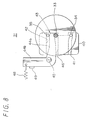
- a cassette player 1 (cassette recording and/or reproducing apparatus).
- a base chassis 2 and a front panel 3 mounted on the front of this base chassis 2.
- a cassette mouth 4 is formed at the center of the front panel 3.
- a front lid 5 is mounted to be rotatable forward and backward around pivots 7 of bearings 6, thus opening or closing the cassette mouth 4.
- the bearings 6 are erected from the base chassis 2 at the lower left and right ends of the cassette mouth 4, and the pivots 7 are provided at the bearings 6 so as to project left and right, respectively.
- the front lid 5 is made of a transparent resin so that the user can visually confirm the inside of the cassette player. Further, the front lid 5 is constantly spring-biased by a predetermined spring means in the rearward, i.e., in the closing direction though not shown.
- a cassette drive mechanism (i.e., so-called mechanical deck) 8 is secured to the front center of the base chassis 2 in an opposing relation to the front lid 5.
- the cassette drive mechanism 8 is composed of a reel drive shaft 9, a capstan 10 and other suitable members such as a magnetic transducer head, a pinch roller or the like, though not shown, similarly to that of the ordinary cassette player. Under the condition that the tape cassette is loaded onto the cassette drive mechanism 8, the reel drive shaft 9 and the capstan 10 are rotated and the magnetic transducer head and the pinch roller (not shown) are inserted into the cassette drive mechanism 8 through the opening portion of the cassette tape, thereby the playback (or the recording) being carried out.
- a slide chassis 11 is supported on the base chassis 2 so that it becomes freely slidable in the front and rear direction. More specifically, a pair of support rails 12 long in the front and rear direction are secured to the left and right sides of the base chassis 2 and the slide chassis 11 is mounted on the supporting rail 12. Front and rear guide members 13 are attached to left and right respective end portions of the slide chassis 11. The guide members 13 are slid along left and right guide rails 14 provided on the base chassis 2 side, whereby the slide chassis 11 is moved in the front and rear direction in a straight line fashion under the condition such that it is inhibited from being moved in the lateral direction.
- the slide chassis 11 has on the front center thereof formed an opening 15 which avoids the cassette drive mechanism 8 so that the slide chassis 11 can be smoothly slid in the front and rear direction without bothering the cassette drive mechanism 8.
- a support shaft 16 is vertically erected from the central portion of the slide chassis 11 and a cassette holder 17 is rotatably supported to the support shaft 16.
- the cassette holder 17 is shaped as a drum-like configuration having a head lining portion and rotatably engaged at its tubular bearing portion 18 to the support shaft 16 to house therein a plurality of tape cassettes C, encircling the cassette drive mechanism 8.
- five cassette compartments 19 of pocket configuration are provided in the circumferential direction and the tape cassettes C are respectively accommodated within the cassette compartments 19 in an erect state.
- each of the cassette compartments 19 is designed so as to hold the tape cassette C under the condition such that the tape cassette C is inclined beforehand toward the outside of the cassette holder 17.
- an inside portion (near the rotation center of the cassette holder 17) of the bottom of the cassette compartment 19 is protruded to form a stepped portion 19a.
- the tape cassette C inserted into the cassette compartment 19 is abutted against the stepped portion 19a, then the tape cassette C is urged to come in contact with the outer edge portion of the cassette compartment 19. Since the tape cassette C is inclined beforehand within the cassette compartment 19, the tape cassette C can be prevented from being recklessly moved in the inside and outside direction.
- the stepped portion 19a might be replaced with an inclined portion 19a inclined toward the outside on the bottom portion of the cassette compartment 19 as shown in FIG. 11 with similar effects being achieved.
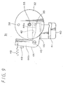
- the cassette holder 17 of drum configuration is supported only to the central portion of the slide chassis 11 and is not stable from this standpoint, the cassette holder 17 is supported at portions of outer circumferential portion to predetermined portions of the slide chassis 11, thereby being prevented from escaping the slide chassis 11. More specifically, a rib 20 is formed around the outer circumferential surface of the cassette holder 17, and guide mechanisms 21 are formed at left and right front end portions of the slide chassis 11 opposing the cassette drive mechanism 8 so as to hold the rib 20 in the vertical direction. As shown in FIG. 12, the guide mechanism 21 is comprised of a pedestal member 22 vertically secured to the slide chassis 11 and a disk-shaped roller 24 rotatably attached to the upper surface of the pedestal member 22 by means of a shaft 23. Since the rib 20 is held and guided between the pedestal member 22 and the disk-shaped roller 24, the cassette holder 17 can be stably rotated with its outer circumferential portion being prevented from escaping the slide chassis 11.
- a rotation drive mechanism 25 for rotating this cassette holder 17 is provided on the slide chassis 11. More specifically, a drive motor 26 is fixed to the slide chassis 11 at a certain place, and the rotation of the drive motor 26 is transmitted through a transmission belt 27 to deceleration gears 28, 29. These deceleration gears 28, 29 are rotatably mounted on the slide chassis 11, and the deceleration gear 29 is meshed with a gear-formed surface 30 which is formed on the entire outer circumferential surface of the cassette holder 17.
- the drive motor 26 is rotated, the rotation force is transmitted through the transmission belt 27 and the deceleration gears 28, 29 to the cassette holder 17. Therefore, the cassette holder 17 is rotated so that the tape cassette C held in each cassette compartment 19 faces the cassette driving mechanism 8 sequentially.
- a movement cam mechanism 31 is provided between the base chassis 12 and the slide chassis 11 so as to move the cassette holder 17 straight, thus loading or unloading the tape cassette C from the cassette driving mechanism 8. Since the cassette holder 17, as described above, is supported on the slide chassis 11 which is supported to be slidable in the forward and backward direction relative to the base chassis 2, the cassette holder 17 can be moved straight in the forward and backward direction together with the slide chassis 11 by the movement cam mechanism 31.
- This movement cam mechanism 31 is constructed as follows.
- a disk-like cam gear 32 as a rotation cam is rotatably supported on the underside of the slider chassis 11 at its center through a pivot 33.
- This cam gear 32 has a first cam pin 34, and second cam pin 35 which is located at rightly the opposite side of the pivot 33 to the first cam 34, or at an angle of 180° relative to the first cam pin 34.
- the second cam pin 35 is located closer to the rotation center than the first cam pin 34.
- a drive motor 36 is adapted to drive this cam gear 32 to rotate. That is, the rotation of the drive motor 36 is transmitted and decelerated through the transmission belt 37 and deceleration gears 38, 39 to the cam gear 32.
- a fixed cam 40 is fixed to the base chassis 2 so as to oppose the cam gear 32.
- the fixed cam 40 has a first cam groove 41 and a second cam groove 42 which are arranged before and after.
- the first cam groove 41 and the second cam groove 42 are extended, substantially straight to have a certain length, in the direction perpendicular to the direction in which the slide chassis 11 is moved.
- the distance between the first and second cam grooves 41 and 42 are substantially equal to that between the first cam pin 34 and the second cam pin 35 of the cam gear 32.
- the first and second cam pins 34 and 35 of the cam gear 32 are moved over and engaged in the first and second cam grooves 41 and 42 of the fixed cam 40, and thus the slide chassis 11 is moved forward or backward relative to the base chassis 2.
- This movement cam mechanism 31 has a limiter mechanism 43 which operates when the slide chassis 11 reaches to its rearmost position That is, according to this embodiment, a limiter arm 44 of an L-letter configuration is rotatably mounted through a pivot 45 on the base chassis 2 at a location near the fixed cam 40. One end portion 44a of this limiter arm 44 is positioned within a wide groove 46 which is formed in the fixed cam 40. The above second cam groove 42 is positioned between the one end portion 44a of the limiter arm 44 and the rear side surface of the groove 46.
- a limiter spring 48 is extended between the other end 44b of the limiter arm 44 and a projection 47 provided at a point on the base chassis 2.
- the limiter arm 44 is constantly spring-biased by the spring-biasing force of the spring 48 to rotate in the counter-clockwise direction as illustrated. or so that the one end 44a is rotated rearwards.
- the limiter spring 48 forces the edge of the other end 44b to be brought in contact with a stopper 49 which is provided to be erect on the base chassis 2.
- the second cam groove 42 is kept to have a predetermined width.
- FIGS. 1 and 4 show the condition such that the slide chassis 11, or the cassette holder 17 is in the most forward end position (first position). In this position, the movement cam mechanism 31 is situated in the condition such that only the first cam pin 34 of the cam gear 32 is engaged in the first cam gear 41 of the fixed cam 40 (see FIG. 7).
- FIGS. 2 through 5 show the situation such that the slide chassis 11, or the cassette holder 17 recedes from the position shown in FIGS. 1 and 4 to the intermediate position (second position).
- the first and second cam pins 34 and 35 of the cam gear 32 are respectively engaged in the first and second cam grooves 41 and 42 of the fixed cam 40 (see FIG. 8).
- the straight line connecting the first cam pin 34 and second cam pin 35 of the cam gear 32 coincides with the movement direction of the slide chassis 11.
- the cam gear 32 is in the dead point, and thus the cam gear is not inadvertently rotated even if a small force is applied to the slide chassis 11.
- the slide chassis 11 is reliably maintained in a fixed state, or the cassette holder 17 is never shifted in its position.
- the front lid 5 is released from being pressed by the slide chassis 11, and thus the front lid 5 is closed. Therefore, the cassette holder 17 is completely drawn back into the cassette player. Even in this position, the cassette holder 17 is able to rotate.
- the cassette holder 17 is rotated by the drive motor 26 of the rotation drive mechanism 25, a tape cassette to be reproduced (or recorded) is selected.
- the cam gear 32 When the selected tape cassette C is positioned to face the front of the cassette drive mechanism 8, the cam gear 32 is further rotated in the counter-clockwise direction by driving the drive motor 36 of the movement cam mechanism 31, whereby the first cam pin 34 of the cam gear 32 is disengaged from the first groove 41 of the fixed cam 40. However, since the second cam pin 35 is engaged in the second cam groove 42, the cam gear 32 is relatively moved backward to the fixed cam 40 and thus the slide chassis 11, or the cassette holder 17 is further moved to recede.
- FIGS. 3 through 6 show the condition such that the slide chassis 11, or the cassette holder 17 has been further moved to recede from the position shown in FIGS. 2 and 5 and to reach the rearmost position (third position). In this position, the selected tape cassette C is loaded on the cassette drive mechanism 8, and the cassette holder 17 is unable to rotate. That is, when the cassette holder 17 is moved to recede from the condition that the tape cassette selected as shown in FIGS. 2 and 6 is located to oppose the front of the cassette drive mechanism 8, the tape cassette is moved together therewith and loaded on the cassette mechanism 8.
- the tape cassette C can be smoothly loaded on the cassette drive mechanism 8.
- the cassette holder 17 is prevented from floating up by the left and right guide mechanism 21, the tape cassette C held by the cassette holder 17 constantly keeps its correct height relative to the cassette drive mechanism 8. Therefore, the tape cassette can be reliably loaded on the cassette drive mechanism 8 without being caught.
- the limiter mechanism 43 of the movement cam mechanism 31 When the slider chassis 11 is situated in the rearmost position, the limiter mechanism 43 of the movement cam mechanism 31 is in the operable state.
- the second cam pin 35 of the cam gear 32 pushes the limiter arm 44 forward against the spring-biasing force of the limiter spring 48, and thus the spring-biasing force of the limiter spring 48 is transmitted to the slide chassis 11 through the limiter arm 44 and cam gear 32. Therefore, the slide chassis 11, or the cassette holder 17 is spring-biased, or urged to move backward. Consequently, the tape cassette is urged against the cassette drive mechanism 8 by the cassette holder 17 so that it can be stably loaded onto the cassette drive mechanism 8 without chattering and correctly reproduced (or recorded).
- any one of the five tape cassettes held within the cassette holder 17 can be selected and reproduced (or recorded).
- the cam gear 32 of the movement cam mechanism 31 is rotated in the opposite direction, or in the clockwise direction so that the cassette holder 17 is returned to the intermediate position shown in FIGS. 2 and 5.
- the tape cassette is unloaded from the cassette drive mechanism 8.
- the cassette holder 17 is able to rotate and the next tape cassette can be selected.
- the five tape cassettes can be continuously reproduced (or recorded) without taking in or out tape cassettes.
- This embodiment of the player is a changer-function-incorporated cassette player having a cassette holder 17 of a drum-like configuration which is able to hold five tape cassettes C therewithin.
- this cassette holder 17 is moved forward and backward by the movement cam mechanism 31, one tape cassette can be loaded on or unloaded from the cassette drive mechanism 8, and thus five tape cassettes can be continuously reproduced (or recorded) with a simple arrangement.
- the guide mechanism 21 is provided for guiding the outer circumferential position of the cassette holder 17 at two places opposite to the cassette drive mechanism 8, thus preventing the cassette holder 17 from floating up, the tape cassette can be smoothly and surely loaded on the cassette drive mechanism 8.
- the movement cam mechanism 31 for moving the cassette holder 17 forward and backward is a special mechanism different from the general cam mechanism, the movement cam mechanism 31 is constructed to be compact.
- the movement cam mechanism 31 in this embodiment is constructed so that when the cam gear 32 is rotated, the cam gear 32 is moved relative to the fixed cam 40, whereby the slide chassis 11 is moved forward and backward relative to the base chassis 2.
- the movement of the slide chassis 11 between the most forward end position and the intermediate position is made by the engagement of the first cam pin 34 of the cam gear 32 with the first cam groove 41 of the fixed cam 40.
- the movement of the slide chassis 11 between the intermediate position and the last end position is made by the engagement of the second cam pin 35 with the second cam groove 42.
- the cam gear 32 when the cam gear 32 is rotated, the first and second cam pins 34 and 35 are moved over and engaged with the first and second cam grooves 41 and 42, whereby the slide chassis 11 is moved relative to the base chassis 2. Therefore, for a constant stroke of movement the cam gear 32 can be constructed to have a smaller diameter than the general cam mechanism, and thus the size of the movement cam mechanism 31 can be reduced by the amount corresponding to the diameter-reduction of the cam gear 32.
- each cassette compartment 19 of the cassette holder 17 is not required to have a limiter mechanism for pressing the tape cassette against the cassette driving mechanism 8.
- the construction of the cassette holder 17 can be simplified.
- This embodiment is realized as a changer-function-incorporated cassette player having its own peculiar structures everywhere, a simple construction and high performance for accurate operation.
- the tape cassette player therefore may have a cassette drive mechanism for reproducing or recording a tape cassette loaded thereon, a drum-shaped cassette holder which holds a plurality of tape cassettes in a circle surrounding said cassette drive mechanism and which is rotated so that each of said tape cassettes opposes said cassette drive mechanism in turn, and a movement mechanism for moving said cassette holder straight between the position in which said tape cassettes can be drawn in or out of said cassette holder and in which said cassette holder can be rotated, and the position in which said cassette cannot be rotated under the condition in which one of said tape cassettes is loaded on said cassette drive mechanism: Therefore, a plurality of said tape cassettes can be continuously reproduced or recorded with a simple construction, and thus this cassette player can contribute to the practical use of a changer-function-incorporated tape cassette player which has not been realized so far. In addition, since this cassette player has a simple construction, it can be made inexpensive.
Landscapes
- Automatic Tape Cassette Changers (AREA)
Description
- The present invention generally relates to cassette players and, more particularly, to a cassette player having a so-called cassette changer function by which a plurality of tape cassettes can be continuously reproduced and/or recorded.
- Recently, a compact disc player, for example, has become commercially available which has the so-called changer function capable of loading a plurality of discs on trays for continuous reproduction of the discs.
- On the other hand, a cassette player for recording (or reproducing) a tape cassette is also desired to have the changer function. US-A-3807741, on which the precharacterising portion of
claim 1 is based, and US-A-3821806 disclose cassette changer mechanisms in which a plurality of cassettes are mounted on a drum-like magazine which can be rotated to select a cassette for engagement with a drive and play device. EP-A-13806 and EP-A-389199 disclose cassette changers in which rotatable cassette magazines are provided in which the cassettes lie flat and are lowered onto a cassette deck. - However, a practical, inexpensive and simple mechanism for the tape cassette player having the cassette changer function has not been proposed yet.
- As described above, a positive mechanism for the cassette player having the cassette changer function is not yet realized and a cassette player with the cassette changer function is not yet commercially available on the market although the need of such cassette player is severe.
- In view of the aforesaid drawbacks of the prior art, it is an object of the present invention to provide a cassette player with a cassette changer function.
- More specifically, it is an object of the present invention to provide a cassette player with a cassette changer function of a simple arrangement.
- Another object of the present invention is to provide a cassette player with a cassette changer function which can be made inexpensively.
- According to the present invention there is provided a cassette player in which a plurality of tape cassettes may be disposed to selectively record and/or reproduce a signal, comprising:
- (a) a tape drive mechanism for transporting a tape housed in a tape cassette;
- (b) a cassette holder of a drum-shaped configuration adapted to house the plurality of tape cassettes and to be rotated such that a selectable tape cassette may be opposed to said tape drive mechanism;
- (c) rotary drive means for rotating said cassette holder such that the selected one of the plurality of tape cassettes is opposed to said tape drive mechanism; and
- (d) means for loading the selected tape cassette in said tape drive mechanism by relative movement of respective chassis on which the tape drive mechanism and cassette holder are mounted, characterised in that the cassette holder surrounds said cassette drive mechanism;
- The invention will be better understood from the following description, when taken together with the accompanying drawings, which are given by way of example only, and in which:
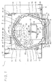
- FIG. 1 is a partly cut-away plan view of an embodiment of the present invention and illustrating the condition such that a cassette holder is placed in the front moved position (first position);
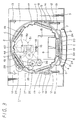
- FIG. 2 is a partly cut-away plan view illustrating a condition where the cassette holder is placed in the intermediate moved position (second position);
- FIG. 3 is a partly cut-away plan view illustrating the condition where the cassette holder is placed in the rear moved position (third position);
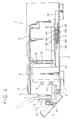
- FIG. 4 is a longitudinal cross-sectional side view illustrating the condition such that the cassette holder is placed in the front moved position (first position);
- FIG. 5 is a longitudinal cross-sectional side view, illustrating the condition such that the cassette holder is placed in the intermediate moved position (second position);
- FIG. 6 is a longitudinal cross-sectional side view illustrating the condition such that the cassette holder is placed in the rear moved position (third position);
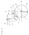
- FIG. 7 is a schematic diagram used to explain operation of a moving cam mechanism of the present invention and which corresponds to FIG. 1;
- FIG. 8 is a schematic diagram used to explain operation of the moving cam mechanism of the present invention and which corresponds to FIG. 2;
- FIG. 9 is a schematic diagram used to explain operation of the moving cam mechanism of the present invention and which corresponds to FIG. 3;
- FIG. 10 is a side view of a cassette compartment of the cassette holder;
- FIG. 11 is a side view of another example of the cassette compartment portion of the cassette holder; and
- FIG. 12 is a side view of a guide mechanism which guides an outer peripheral portion of the cassette holder.
- The present invention will now be described in detail with reference to the accompanying drawings.
- As illustrated, there is generally shown a cassette player 1 (cassette recording and/or reproducing apparatus). There are also shown a
base chassis 2 and afront panel 3 mounted on the front of thisbase chassis 2. Acassette mouth 4 is formed at the center of thefront panel 3. Afront lid 5 is mounted to be rotatable forward and backward aroundpivots 7 ofbearings 6, thus opening or closing thecassette mouth 4. Thebearings 6 are erected from thebase chassis 2 at the lower left and right ends of thecassette mouth 4, and thepivots 7 are provided at thebearings 6 so as to project left and right, respectively. Thefront lid 5 is made of a transparent resin so that the user can visually confirm the inside of the cassette player. Further, thefront lid 5 is constantly spring-biased by a predetermined spring means in the rearward, i.e., in the closing direction though not shown. - A cassette drive mechanism (i.e., so-called mechanical deck) 8 is secured to the front center of the
base chassis 2 in an opposing relation to thefront lid 5. Thecassette drive mechanism 8 is composed of areel drive shaft 9, acapstan 10 and other suitable members such as a magnetic transducer head, a pinch roller or the like, though not shown, similarly to that of the ordinary cassette player. Under the condition that the tape cassette is loaded onto thecassette drive mechanism 8, thereel drive shaft 9 and thecapstan 10 are rotated and the magnetic transducer head and the pinch roller (not shown) are inserted into thecassette drive mechanism 8 through the opening portion of the cassette tape, thereby the playback (or the recording) being carried out. - A
slide chassis 11 is supported on thebase chassis 2 so that it becomes freely slidable in the front and rear direction. More specifically, a pair ofsupport rails 12 long in the front and rear direction are secured to the left and right sides of thebase chassis 2 and theslide chassis 11 is mounted on the supportingrail 12. Front andrear guide members 13 are attached to left and right respective end portions of theslide chassis 11. Theguide members 13 are slid along left andright guide rails 14 provided on thebase chassis 2 side, whereby theslide chassis 11 is moved in the front and rear direction in a straight line fashion under the condition such that it is inhibited from being moved in the lateral direction. Theslide chassis 11 has on the front center thereof formed anopening 15 which avoids thecassette drive mechanism 8 so that theslide chassis 11 can be smoothly slid in the front and rear direction without bothering thecassette drive mechanism 8. - A
support shaft 16 is vertically erected from the central portion of theslide chassis 11 and acassette holder 17 is rotatably supported to thesupport shaft 16. Thecassette holder 17 is shaped as a drum-like configuration having a head lining portion and rotatably engaged at its tubular bearingportion 18 to thesupport shaft 16 to house therein a plurality of tape cassettes C, encircling thecassette drive mechanism 8. In this embodiment, fivecassette compartments 19 of pocket configuration are provided in the circumferential direction and the tape cassettes C are respectively accommodated within thecassette compartments 19 in an erect state. - In order to prevent the tape cassette C thus accommodated from being moved recklessly within the
cassette compartment 19, each of thecassette compartments 19 is designed so as to hold the tape cassette C under the condition such that the tape cassette C is inclined beforehand toward the outside of thecassette holder 17. According to this embodiment, as shown in FIG. 10, an inside portion (near the rotation center of the cassette holder 17) of the bottom of thecassette compartment 19 is protruded to form astepped portion 19a. When the tape cassette C inserted into thecassette compartment 19 is abutted against thestepped portion 19a, then the tape cassette C is urged to come in contact with the outer edge portion of thecassette compartment 19. Since the tape cassette C is inclined beforehand within thecassette compartment 19, the tape cassette C can be prevented from being recklessly moved in the inside and outside direction. Alternatively, thestepped portion 19a might be replaced with aninclined portion 19a inclined toward the outside on the bottom portion of thecassette compartment 19 as shown in FIG. 11 with similar effects being achieved. - Since the
cassette holder 17 of drum configuration is supported only to the central portion of theslide chassis 11 and is not stable from this standpoint, thecassette holder 17 is supported at portions of outer circumferential portion to predetermined portions of theslide chassis 11, thereby being prevented from escaping theslide chassis 11. More specifically, arib 20 is formed around the outer circumferential surface of thecassette holder 17, andguide mechanisms 21 are formed at left and right front end portions of theslide chassis 11 opposing thecassette drive mechanism 8 so as to hold therib 20 in the vertical direction. As shown in FIG. 12, theguide mechanism 21 is comprised of apedestal member 22 vertically secured to theslide chassis 11 and a disk-shaped roller 24 rotatably attached to the upper surface of thepedestal member 22 by means of ashaft 23. Since therib 20 is held and guided between thepedestal member 22 and the disk-shaped roller 24, thecassette holder 17 can be stably rotated with its outer circumferential portion being prevented from escaping theslide chassis 11. - A
rotation drive mechanism 25 for rotating thiscassette holder 17 is provided on theslide chassis 11. More specifically, adrive motor 26 is fixed to theslide chassis 11 at a certain place, and the rotation of thedrive motor 26 is transmitted through atransmission belt 27 todeceleration gears deceleration gears slide chassis 11, and thedeceleration gear 29 is meshed with a gear-formedsurface 30 which is formed on the entire outer circumferential surface of thecassette holder 17. Thus, when thedrive motor 26 is rotated, the rotation force is transmitted through thetransmission belt 27 and thedeceleration gears cassette holder 17. Therefore, thecassette holder 17 is rotated so that the tape cassette C held in eachcassette compartment 19 faces thecassette driving mechanism 8 sequentially. - Moreover, a
movement cam mechanism 31 is provided between thebase chassis 12 and theslide chassis 11 so as to move thecassette holder 17 straight, thus loading or unloading the tape cassette C from thecassette driving mechanism 8. Since thecassette holder 17, as described above, is supported on theslide chassis 11 which is supported to be slidable in the forward and backward direction relative to thebase chassis 2, thecassette holder 17 can be moved straight in the forward and backward direction together with theslide chassis 11 by themovement cam mechanism 31. Thismovement cam mechanism 31 is constructed as follows. - A disk-
like cam gear 32 as a rotation cam is rotatably supported on the underside of theslider chassis 11 at its center through apivot 33. Thiscam gear 32 has afirst cam pin 34, andsecond cam pin 35 which is located at rightly the opposite side of thepivot 33 to thefirst cam 34, or at an angle of 180° relative to thefirst cam pin 34. Thesecond cam pin 35 is located closer to the rotation center than thefirst cam pin 34. Adrive motor 36 is adapted to drive thiscam gear 32 to rotate. That is, the rotation of thedrive motor 36 is transmitted and decelerated through thetransmission belt 37 and deceleration gears 38, 39 to thecam gear 32. - A fixed
cam 40 is fixed to thebase chassis 2 so as to oppose thecam gear 32. The fixedcam 40 has afirst cam groove 41 and asecond cam groove 42 which are arranged before and after. Thefirst cam groove 41 and thesecond cam groove 42 are extended, substantially straight to have a certain length, in the direction perpendicular to the direction in which theslide chassis 11 is moved. The distance between the first andsecond cam grooves first cam pin 34 and thesecond cam pin 35 of thecam gear 32. As will be described later, the first and second cam pins 34 and 35 of thecam gear 32 are moved over and engaged in the first andsecond cam grooves cam 40, and thus theslide chassis 11 is moved forward or backward relative to thebase chassis 2. - This
movement cam mechanism 31 has alimiter mechanism 43 which operates when theslide chassis 11 reaches to its rearmost position That is, according to this embodiment, alimiter arm 44 of an L-letter configuration is rotatably mounted through apivot 45 on thebase chassis 2 at a location near the fixedcam 40. Oneend portion 44a of thislimiter arm 44 is positioned within awide groove 46 which is formed in the fixedcam 40. The abovesecond cam groove 42 is positioned between the oneend portion 44a of thelimiter arm 44 and the rear side surface of thegroove 46. - A
limiter spring 48 is extended between theother end 44b of thelimiter arm 44 and aprojection 47 provided at a point on thebase chassis 2. Thelimiter arm 44 is constantly spring-biased by the spring-biasing force of thespring 48 to rotate in the counter-clockwise direction as illustrated. or so that the oneend 44a is rotated rearwards. When thislimiter arm 44 is in the normal condition, thelimiter spring 48 forces the edge of theother end 44b to be brought in contact with astopper 49 which is provided to be erect on thebase chassis 2. Thus, thesecond cam groove 42 is kept to have a predetermined width. When theslider 11 has been moved to the rearmost position, thesecond cam pin 35 of thecam gear 32 pushes thislimiter arm 44 against the spring-biasing force of thelimiter spring 48. - Operation of the cassette player thus constructed according to this embodiment will be described below.
- FIGS. 1 and 4 show the condition such that the
slide chassis 11, or thecassette holder 17 is in the most forward end position (first position). In this position, themovement cam mechanism 31 is situated in the condition such that only thefirst cam pin 34 of thecam gear 32 is engaged in thefirst cam gear 41 of the fixed cam 40 (see FIG. 7). - When the
slide chassis 11 is in the most forward end position,projections 51, which are provided on both left and right sides of acover member 50 that is mounted on the front of theslide chassis 11, push the left and right sides of thefront lid 5 from the inside, thus opening thefront lid 5 against the spring-biasing force for closing. A part of thecassette holder 17 is exposed to the outside of the cassette player through themouth 4, so that the tape cassette C can be loaded in or unloaded from thecassette compartment 19. At this position, thecassette holder 17 is made rotatable. When thecassette holder 17 is rotated by thedrive motor 26 of therotation drive mechanism 25, the tape cassettes can be exchanged at the following cassette compartments 19. - When the
drive motor 36 of themovement cam mechanism 31 is driven to rotate thecam gear 32 in the counter-clockwise direction as illustrated, thecam gear 32 is relatively moved backward to the fixedcam 40 since thefirst cam pin 34 is engaged in thefirst cam groove 41 of the fixedcam 40. Thus, theslide chassis 11, orcassette holder 17 is moved backward. - FIGS. 2 through 5 show the situation such that the
slide chassis 11, or thecassette holder 17 recedes from the position shown in FIGS. 1 and 4 to the intermediate position (second position). When themovement mechanism 31 is situated in this intermediate position, the first and second cam pins 34 and 35 of thecam gear 32 are respectively engaged in the first andsecond cam grooves first cam pin 34 andsecond cam pin 35 of thecam gear 32 coincides with the movement direction of theslide chassis 11. In other words, thecam gear 32 is in the dead point, and thus the cam gear is not inadvertently rotated even if a small force is applied to theslide chassis 11. Thus, theslide chassis 11 is reliably maintained in a fixed state, or thecassette holder 17 is never shifted in its position. - Under the condition such that the
slide chassis 11 has receded to the intermediate position, thefront lid 5 is released from being pressed by theslide chassis 11, and thus thefront lid 5 is closed. Therefore, thecassette holder 17 is completely drawn back into the cassette player. Even in this position, thecassette holder 17 is able to rotate. When thecassette holder 17 is rotated by thedrive motor 26 of therotation drive mechanism 25, a tape cassette to be reproduced (or recorded) is selected. - When the selected tape cassette C is positioned to face the front of the
cassette drive mechanism 8, thecam gear 32 is further rotated in the counter-clockwise direction by driving thedrive motor 36 of themovement cam mechanism 31, whereby thefirst cam pin 34 of thecam gear 32 is disengaged from thefirst groove 41 of the fixedcam 40. However, since thesecond cam pin 35 is engaged in thesecond cam groove 42, thecam gear 32 is relatively moved backward to the fixedcam 40 and thus theslide chassis 11, or thecassette holder 17 is further moved to recede. - FIGS. 3 through 6 show the condition such that the
slide chassis 11, or thecassette holder 17 has been further moved to recede from the position shown in FIGS. 2 and 5 and to reach the rearmost position (third position). In this position, the selected tape cassette C is loaded on thecassette drive mechanism 8, and thecassette holder 17 is unable to rotate. That is, when thecassette holder 17 is moved to recede from the condition that the tape cassette selected as shown in FIGS. 2 and 6 is located to oppose the front of thecassette drive mechanism 8, the tape cassette is moved together therewith and loaded on thecassette mechanism 8. - In the loading operation of the tape cassette C on the
cassette drive mechanism 8, since the outer circumferential portion of thecassette holder 8 is guided by theguide mechanism 21 as described above, the tape cassette C can be smoothly loaded on thecassette drive mechanism 8. In other words, since thecassette holder 17 is prevented from floating up by the left andright guide mechanism 21, the tape cassette C held by thecassette holder 17 constantly keeps its correct height relative to thecassette drive mechanism 8. Therefore, the tape cassette can be reliably loaded on thecassette drive mechanism 8 without being caught. - When the
slider chassis 11 is situated in the rearmost position, thelimiter mechanism 43 of themovement cam mechanism 31 is in the operable state. In other words, as will be obvious from FIG. 9, thesecond cam pin 35 of thecam gear 32 pushes thelimiter arm 44 forward against the spring-biasing force of thelimiter spring 48, and thus the spring-biasing force of thelimiter spring 48 is transmitted to theslide chassis 11 through thelimiter arm 44 andcam gear 32. Therefore, theslide chassis 11, or thecassette holder 17 is spring-biased, or urged to move backward. Consequently, the tape cassette is urged against thecassette drive mechanism 8 by thecassette holder 17 so that it can be stably loaded onto thecassette drive mechanism 8 without chattering and correctly reproduced (or recorded). - As described above, according to this embodiment, any one of the five tape cassettes held within the
cassette holder 17 can be selected and reproduced (or recorded). After the end of the reproduction (or recording) of the selected tape cassette, thecam gear 32 of themovement cam mechanism 31 is rotated in the opposite direction, or in the clockwise direction so that thecassette holder 17 is returned to the intermediate position shown in FIGS. 2 and 5. Then, the tape cassette is unloaded from thecassette drive mechanism 8. Thus, thecassette holder 17 is able to rotate and the next tape cassette can be selected. According to this embodiment, the five tape cassettes can be continuously reproduced (or recorded) without taking in or out tape cassettes. - This embodiment of the player, as described above, is a changer-function-incorporated cassette player having a
cassette holder 17 of a drum-like configuration which is able to hold five tape cassettes C therewithin. When thiscassette holder 17 is moved forward and backward by themovement cam mechanism 31, one tape cassette can be loaded on or unloaded from thecassette drive mechanism 8, and thus five tape cassettes can be continuously reproduced (or recorded) with a simple arrangement. - Moreover, according to this embodiment of the cassette player, since the
guide mechanism 21 is provided for guiding the outer circumferential position of thecassette holder 17 at two places opposite to thecassette drive mechanism 8, thus preventing thecassette holder 17 from floating up, the tape cassette can be smoothly and surely loaded on thecassette drive mechanism 8. - In addition, according to this embodiment, since the
movement cam mechanism 31 for moving thecassette holder 17 forward and backward is a special mechanism different from the general cam mechanism, themovement cam mechanism 31 is constructed to be compact. In other words, since themovement cam mechanism 31 in this embodiment is constructed so that when thecam gear 32 is rotated, thecam gear 32 is moved relative to the fixedcam 40, whereby theslide chassis 11 is moved forward and backward relative to thebase chassis 2. The movement of theslide chassis 11 between the most forward end position and the intermediate position is made by the engagement of thefirst cam pin 34 of thecam gear 32 with thefirst cam groove 41 of the fixedcam 40. The movement of theslide chassis 11 between the intermediate position and the last end position is made by the engagement of thesecond cam pin 35 with thesecond cam groove 42. In other words, when thecam gear 32 is rotated, the first and second cam pins 34 and 35 are moved over and engaged with the first andsecond cam grooves slide chassis 11 is moved relative to thebase chassis 2. Therefore, for a constant stroke of movement thecam gear 32 can be constructed to have a smaller diameter than the general cam mechanism, and thus the size of themovement cam mechanism 31 can be reduced by the amount corresponding to the diameter-reduction of thecam gear 32. - Furthermore, according to this embodiment, since the
movement cam mechanism 31 for moving thecassette holder 17 forward and backward is provided with alimiter mechanism 43 for pressing the tape cassette C against thecassette drive mechanism 8, eachcassette compartment 19 of thecassette holder 17 is not required to have a limiter mechanism for pressing the tape cassette against thecassette driving mechanism 8. Thus, the construction of thecassette holder 17 can be simplified. - This embodiment is realized as a changer-function-incorporated cassette player having its own peculiar structures everywhere, a simple construction and high performance for accurate operation.
- The tape cassette player therefore may have a cassette drive mechanism for reproducing or recording a tape cassette loaded thereon, a drum-shaped cassette holder which holds a plurality of tape cassettes in a circle surrounding said cassette drive mechanism and which is rotated so that each of said tape cassettes opposes said cassette drive mechanism in turn, and a movement mechanism for moving said cassette holder straight between the position in which said tape cassettes can be drawn in or out of said cassette holder and in which said cassette holder can be rotated, and the position in which said cassette cannot be rotated under the condition in which one of said tape cassettes is loaded on said cassette drive mechanism: Therefore, a plurality of said tape cassettes can be continuously reproduced or recorded with a simple construction, and thus this cassette player can contribute to the practical use of a changer-function-incorporated tape cassette player which has not been realized so far. In addition, since this cassette player has a simple construction, it can be made inexpensive.
and in that said tape drive mechanism is secured on a base chassis and a tape cassette loading means for supporting said cassette holder is mounted on a slide chassis supported to reciprocate on said base chassis, said tape cassette loading means comprising: a rotating cam having first and second cam pins pivotally attached to one of said base chassis and said slide chassis, and first and second cam grooves provided on the other of said base chassis and said slide chassis, wherein said first and second cam pins are engagable by and movable across said first and second cam grooves by rotation of said rotation cam, thereby to move said slide chassis relative to said base chassis.
Claims (5)
- A cassette player (1) in which a plurality of tape cassettes (16) may be disposed to selectively record and/or reproduce a signal, comprising:(a) a tape drive mechanism (8) for transporting a tape housed in a tape cassette;(b) a cassette holder (17) of a drum-shaped configuration adapted to house the plurality of tape cassettes and to be rotated such that a selectable tape cassette may be opposed to said tape drive mechanism;(c) rotary drive means (26) for rotating said cassette holder such that the selected one of the plurality of tape cassettes is opposed to said drive mechanism; and(d) means (31) for loading the selected tape cassette in said tape drive mechanism by relative movement of respective chassis on which the tape drive mechanism (8) and cassette holder (17) are mounted, characterised in that the cassette holder surrounds said cassette drive mechanism;and in that said tape drive mechanism is secured on a base chassis (2) and a tape cassette loading means for supporting said cassette holder is mounted on a slide chassis (11) supported to reciprocate on said base chassis, said tape cassette loading means (31) comprising: a rotating cam (32) having first (34) and second (35) cam pins pivotally attached to one of said base chassis and said slide chassis, and first and second cam grooves (41,42) provided on the other of said base chassis and said slide chassis, wherein said first and second cam pins are engagable by and movable across said first and second cam grooves by rotation of said rotation cam, thereby to move said slide chassis relative to said base chassis.
- A cassette player according to claim 1 wherein the means (31) for engaging the tape drive mechanism with the selected tape cassette are adapted to move the cassette holder (17) substantially linearly so that the selected tape cassette (16) is loaded onto the tape drive mechanism (8).
- A cassette player according to claim 1 or 2, wherein said cassette holder has a rib (20) formed around its outer circumferential surface and a guide mechanism (21) is provided at the portion opposing said cassette drive mechanism (8) to guide said rib so that said cassette holder is securely positioned.
- A cassette player according to claim 1, wherein said tape cassette loading means (31) comprising said rotating cam is provided with a limiter mechanism (43) for urging said tape cassette against said cassette drive mechanism.
- A cassette player according to any preceding claim, wherein said cassette holder has formed on a bottom portion of a cassette compartment (19) thereof a stepped portion (19a) or an inclined portion (19b) for holding and housing said tape cassettes in an inclined state.
Applications Claiming Priority (2)
| Application Number | Priority Date | Filing Date | Title |
|---|---|---|---|
| JP93442/91 | 1991-03-29 | ||
| JP3093442A JPH04302842A (en) | 1991-03-29 | 1991-03-29 | Cassette player |
Publications (3)
| Publication Number | Publication Date |
|---|---|
| EP0506459A2 EP0506459A2 (en) | 1992-09-30 |
| EP0506459A3 EP0506459A3 (en) | 1993-03-03 |
| EP0506459B1 true EP0506459B1 (en) | 1995-05-10 |
Family
ID=14082443
Family Applications (1)
| Application Number | Title | Priority Date | Filing Date |
|---|---|---|---|
| EP92302714A Expired - Lifetime EP0506459B1 (en) | 1991-03-29 | 1992-03-27 | Cassette player |
Country Status (4)
| Country | Link |
|---|---|
| US (1) | US5539594A (en) |
| EP (1) | EP0506459B1 (en) |
| JP (1) | JPH04302842A (en) |
| DE (1) | DE69202380T2 (en) |
Families Citing this family (4)
| Publication number | Priority date | Publication date | Assignee | Title |
|---|---|---|---|---|
| JP3361026B2 (en) * | 1997-02-28 | 2003-01-07 | 富士通株式会社 | Library device |
| US6804080B1 (en) * | 1997-09-03 | 2004-10-12 | Segway Systems, Llc | Media carousel changer for data systems |
| DE10055626C2 (en) * | 2000-11-09 | 2003-10-23 | Bdt Buero Datentech Gmbh | Automatic library for cartridges of data storage tapes |
| KR100692616B1 (en) * | 2004-12-31 | 2007-03-13 | 삼성전자주식회사 | Video cassette recorder |
Family Cites Families (14)
| Publication number | Priority date | Publication date | Assignee | Title |
|---|---|---|---|---|
| US3127178A (en) * | 1960-06-29 | 1964-03-31 | Tape playing machine | |
| US3127179A (en) * | 1960-06-29 | 1964-03-31 | Tape playing machine | |
| US3511508A (en) * | 1968-01-16 | 1970-05-12 | Itsuki Ban | Tape player utilizing plurality of endless loop magnetic tape cartridges |
| US3698722A (en) * | 1970-09-21 | 1972-10-17 | Itsuki Ban | Control circuit for multiple tape cartridge playing apparatus |
| US3807741A (en) * | 1971-01-16 | 1974-04-30 | Teac Corp | Automatic cassette changer |
| US3821806A (en) * | 1971-06-20 | 1974-06-28 | Teac Corp | Cassette tape apparatus |
| US4247876A (en) * | 1978-12-18 | 1981-01-27 | Lanier Business Products, Inc. | Dictation recording and transcribing system utilizing a multiple media cartridge apparatus |
| DE3110480A1 (en) * | 1981-03-18 | 1982-10-21 | Blaupunkt-Werke Gmbh, 3200 Hildesheim | SMALL CASSETTE DEVICE |
| EP0060396A3 (en) * | 1981-03-18 | 1983-02-16 | Blaupunkt-Werke GmbH | Tape recorder for minicassettes |
| JPH0675329B2 (en) * | 1986-02-18 | 1994-09-21 | ソニー株式会社 | Disc player |
| JPH07114050B2 (en) * | 1988-03-28 | 1995-12-06 | 三洋電機株式会社 | Cassette loading mechanism |
| US5148332A (en) * | 1989-03-20 | 1992-09-15 | Mitsubishi Denki Kabushiki Kaisha | Automatic cassette tape recording and reproducing apparatus with a pivotable magazine holder |
| US5136562A (en) * | 1989-04-11 | 1992-08-04 | Staar Development, S.A. | Automatic changer for information storage devices |
| US5115419A (en) * | 1989-05-18 | 1992-05-19 | Yamaha Corporation | Disc playback device capable of continuously playing back a plurality of discs |
-
1991
- 1991-03-29 JP JP3093442A patent/JPH04302842A/en active Pending
-
1992
- 1992-03-27 DE DE69202380T patent/DE69202380T2/en not_active Expired - Fee Related
- 1992-03-27 EP EP92302714A patent/EP0506459B1/en not_active Expired - Lifetime
-
1995
- 1995-05-03 US US08/433,595 patent/US5539594A/en not_active Expired - Fee Related
Also Published As
| Publication number | Publication date |
|---|---|
| US5539594A (en) | 1996-07-23 |
| EP0506459A3 (en) | 1993-03-03 |
| JPH04302842A (en) | 1992-10-26 |
| DE69202380T2 (en) | 1995-10-05 |
| EP0506459A2 (en) | 1992-09-30 |
| DE69202380D1 (en) | 1995-06-14 |
Similar Documents
| Publication | Publication Date | Title |
|---|---|---|
| US3770908A (en) | Magnetic disc recorder with a carriage for receiving and moving a cassette into playing position | |
| JP3413607B2 (en) | Information carrier transfer device | |
| KR0164228B1 (en) | Disc reproducing apparatus | |
| US3833224A (en) | Tape recorder with cassette invertor | |
| EP0506459B1 (en) | Cassette player | |
| EP0214820B1 (en) | Magnetic tape cartridges | |
| EP0228904B1 (en) | Magnetic tape cartridges | |
| JP2722512B2 (en) | Disk storage case and disk loading device | |
| US4160281A (en) | Cassette changer | |
| EP0431912B1 (en) | Cassette holder for recording and/or reproducing apparatus | |
| EP0557726B1 (en) | Cassette tape player compatible with cassette tapes of different formats | |
| US7162726B2 (en) | Disk apparatus | |
| JP3164221B2 (en) | Cassette autochanger device | |
| EP0944071B1 (en) | Positioning system for use in an information recording /reproducing apparatus | |
| JP3155958B2 (en) | Disc changer | |
| US5917786A (en) | Reduced size automatic loading disc changer | |
| JP2954522B2 (en) | Composite recording / playback device | |
| EP0219950A2 (en) | Magnetic tape cartridges | |
| JP3536721B2 (en) | Cartridge transfer device | |
| JP2728223B2 (en) | Magnetic disk drive | |
| JP3049742B2 (en) | Disk unit | |
| JP3130505B2 (en) | Disk auto changer | |
| JPH04268248A (en) | Disk cartridge carrying device | |
| JPH04302843A (en) | Cassette player | |
| JPH08235706A (en) | Recording medium mounting device |
Legal Events
| Date | Code | Title | Description |
|---|---|---|---|
| PUAI | Public reference made under article 153(3) epc to a published international application that has entered the european phase |
Free format text: ORIGINAL CODE: 0009012 |
|
| AK | Designated contracting states |
Kind code of ref document: A2 Designated state(s): DE FR GB |
|
| PUAL | Search report despatched |
Free format text: ORIGINAL CODE: 0009013 |
|
| AK | Designated contracting states |
Kind code of ref document: A3 Designated state(s): DE FR GB |
|
| 17P | Request for examination filed |
Effective date: 19930817 |
|
| 17Q | First examination report despatched |
Effective date: 19931115 |
|
| GRAA | (expected) grant |
Free format text: ORIGINAL CODE: 0009210 |
|
| AK | Designated contracting states |
Kind code of ref document: B1 Designated state(s): DE FR GB |
|
| REF | Corresponds to: |
Ref document number: 69202380 Country of ref document: DE Date of ref document: 19950614 |
|
| ET | Fr: translation filed | ||
| PLBE | No opposition filed within time limit |
Free format text: ORIGINAL CODE: 0009261 |
|
| STAA | Information on the status of an ep patent application or granted ep patent |
Free format text: STATUS: NO OPPOSITION FILED WITHIN TIME LIMIT |
|
| 26N | No opposition filed | ||
| PGFP | Annual fee paid to national office [announced via postgrant information from national office to epo] |
Ref country code: FR Payment date: 20010313 Year of fee payment: 10 |
|
| PGFP | Annual fee paid to national office [announced via postgrant information from national office to epo] |
Ref country code: DE Payment date: 20010319 Year of fee payment: 10 |
|
| PGFP | Annual fee paid to national office [announced via postgrant information from national office to epo] |
Ref country code: GB Payment date: 20010321 Year of fee payment: 10 |
|
| REG | Reference to a national code |
Ref country code: GB Ref legal event code: IF02 |
|
| PG25 | Lapsed in a contracting state [announced via postgrant information from national office to epo] |
Ref country code: GB Free format text: LAPSE BECAUSE OF NON-PAYMENT OF DUE FEES Effective date: 20020327 |
|
| PG25 | Lapsed in a contracting state [announced via postgrant information from national office to epo] |
Ref country code: DE Free format text: LAPSE BECAUSE OF NON-PAYMENT OF DUE FEES Effective date: 20021001 |
|
| GBPC | Gb: european patent ceased through non-payment of renewal fee |
Effective date: 20020327 |
|
| PG25 | Lapsed in a contracting state [announced via postgrant information from national office to epo] |
Ref country code: FR Free format text: LAPSE BECAUSE OF NON-PAYMENT OF DUE FEES Effective date: 20021129 |
|
| REG | Reference to a national code |
Ref country code: FR Ref legal event code: ST |