EP0376242B1 - Tape-loading mechanism for use in magnetic recording/reproducing apparatus - Google Patents
Tape-loading mechanism for use in magnetic recording/reproducing apparatus Download PDFInfo
- Publication number
- EP0376242B1 EP0376242B1 EP89123933A EP89123933A EP0376242B1 EP 0376242 B1 EP0376242 B1 EP 0376242B1 EP 89123933 A EP89123933 A EP 89123933A EP 89123933 A EP89123933 A EP 89123933A EP 0376242 B1 EP0376242 B1 EP 0376242B1
- Authority
- EP
- European Patent Office
- Prior art keywords
- tape
- guide roller
- guide
- preventing means
- damage preventing
- Prior art date
- Legal status (The legal status is an assumption and is not a legal conclusion. Google has not performed a legal analysis and makes no representation as to the accuracy of the status listed.)
- Expired - Lifetime
Links
Images


Classifications
-
- G—PHYSICS
- G11—INFORMATION STORAGE
- G11B—INFORMATION STORAGE BASED ON RELATIVE MOVEMENT BETWEEN RECORD CARRIER AND TRANSDUCER
- G11B15/00—Driving, starting or stopping record carriers of filamentary or web form; Driving both such record carriers and heads; Guiding such record carriers or containers therefor; Control thereof; Control of operating function
- G11B15/60—Guiding record carrier
- G11B15/66—Threading; Loading; Automatic self-loading
- G11B15/665—Threading; Loading; Automatic self-loading by extracting loop of record carrier from container
- G11B15/6653—Threading; Loading; Automatic self-loading by extracting loop of record carrier from container to pull the record carrier against drum
- G11B15/6656—Threading; Loading; Automatic self-loading by extracting loop of record carrier from container to pull the record carrier against drum using two-sided extraction, i.e. "M-type"
Definitions
- various operation modes such as recording, play, freeze (i.e., still image reproduction), slow play, fast-forward play, fast-rewind play, fast forward, and fast rewind, are selectively established with a mode-establishing mechanism and its associated circuits. If an eject key is operated, the tape-loading mechanism draws the tape back into the cassette, and the front loading mechanism returns the cassette from the cassette-loading position to the cassette insertion port.
- the tape loading mechanism of this apparatus for bringing a tape into contact with a drum carrying the heads for recording or reproducing comprises a pair of tape pulling members which depending on a set function of the apparatus move along guides in predetermined directions for pulling the tape out of a cassette and guiding it on a predetermined tape travel path or for returning the tape into the cassette.
- Each of the movable tape pulling members comprises a tape guide roller and holding members are provided at the guide end positions for holding the respective tape pulling members at these positions.
- no means are provided for preventing a damage of the tape when the latter slackens and is disengaged from the tape guide rollers.
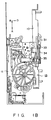
- Figs. 1A, 1B and 1C are top, side and bottom views, respectively, of a tape-loading mechanism employed in the magnetic recording/reproducing apparatus according to the first embodiment of the present invention.
- frame member 11 is coupled to one end of main chassis 10.
- Cassette holder 12 is supported by frame member 11 such that it is movable in the directions indicated by arrows A, B and D (the direction indicated by arrow D is perpendicular to the directions indicated by arrows A and B).
- Cassette holder 12 is adapted to receive cassette C (which is not shown in Figs. 1A, 1B and 1C, for simplicity) when it is located at the cassette insertion port.
- front loading mechanism 13 In response to the insertion of cassette C into cassette holder 12, front loading mechanism 13 is automatically driven. This front loading mechanism moves cassette holder 12 in direction B, together with cassette C inserted therein, until cassette holder 12 reaches a predetermined position. Then, front loading mechanism 13 moves cassette holder 12 in direction D. As a result, cassette C is fitted on supply reel bases 14 and 15, which are parts of a tape-driving mechanism.
- driving gear 29 is fitted around the periphery of the rotating member of capstan motor 27.
- Vertically-movable gear 30 is arranged such that it faces driving gear 29.
- First end 31a of vertically-swingable switch lever 31 is in contact with the upper side of vertically-movable gear 30.
- Second end 31b of the switch lever 31 engageable with one side of first mode-switching cam 32a, which is one of the axially-arranged mode-switching cams of the operation mode-switching mechanism.
- vertically-movable gear 30 is coaxial with pulley 33, and this pulley 33 is coupled to main chassis 10 such that it is rotatable around shaft 33a.
- Vertically-movable gear 30 is located around pulley 33 and is urged toward pulley 33 in the axial direction of shaft 33a by spring 30a. The rotation of vertically-movable gear 30 is transmitted to pulley 33 through stop members 33b. That is, vertically-movable gear 30 and pulley 33 are rotatable in the same direction.
- first and second tape-pulling members 39a and 39b are fitted in first and second guide holes 38a and 38b, respectively, such that they are movable within the guide holes.
- Slanted post 40a substantially parallel to cylinder 37 and guide roller 41a substantially perpendicular to main chassis 10 are provided for first tape-pulling member 39a such that they are located side by side with reference to each other.
- slanted post 40b substantially parallel to cylinder 37 and guide roller 41b substantially perpendicular to main chassis 10 are provided for second tape-pulling member 39b such that they are located side by side with reference to each other.
- Pin 45b located at the other end of driving lever 45 engages with cam groove 32f formed in second mode-switching cam 32e, and this cam 32e is rotated within a predetermined angular range by loading motor 32. Therefore, driving lever 45 is driven by the movement of second mode-switching cam 32e, and transmits the driving force to first and second tape-pulling members 39a and 39b, through half-gear 44, first and second driving gears 43a and 43b, and first and second links 42a and 42b, thereby performing tape loading.
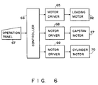
- First and second mode-switching cams 32a and 32e mentioned above are coaxial with the other mode-switching cams (not shown). All these mode-switching cams are rotated within the same angular range by loading motor 32, and their angles of rotation are determined in accordance with the operation modes of the VTR. As is shown in Fig. 6, loading motor 32 is driven by motor driver 65 under the control of controller 66. In accordance with the user's operation of control panel 67, controller 66 determines an operation mode of the VTR. Controller 66 causes the mode-switching cams to be rotated by the angle corresponding to the determined operation mode. Further, controller 66 controls motor driver 68 in accordance with the determined operation mode, to thereby drive capstan motor 27.
- the holding members 71a, 71b and the tape control portions 72a, 72b have the constructions shown in Figs. 7A to 7C. As is shown in these Figures, tape control portions 72a and 72b are provided in correspondence to one side facing cylinder 37 on holding members 71a and 71b. The heights of tape control portions 72a and 72b as measured from holding members 71a and 71b are determined such that their upper surfaces are substantially at the same level as, or slightly lower than, flanges 74a and 74b formed at the lower end of tape-winding portions 73a and 73b of guide rollers 41a and 41b.
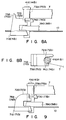
- Figs. 8A and 8B are views of tape control portions 72a and 72b employed in the tape-loading mechanism of the second embodiment of the present invention. Since tape control portions 72a and 72b differ from each other merely in their positions relative to respective guide rollers 41a and 41b, only the construction including first tape-pulling member 39a is shown in Figs. 8A and 8B, for simplicity. As for the construction including second tape-pulling member 39b, the corresponding parts are denoted by the reference numerals enclosed within the parentheses.
- tape control portion 72a corresponding to first tape-pulling member 39a is integral with holding member 71a.
- tape control portion 72a is constituted by the upper surface of holding member 71a.
- tape control section 72a is located only on one side of guide roller 41a, whereas in the second embodiment, it is constituted by the entire upper surface of holding member 71a and is located on both sides of guide roller 41a.
- projection 75a used for guiding tape T is formed on the surface of holding member 71a, i.e., on tape control portion 72a.
- Holding member 71b corresponding to second tape-pulling member 39b has tape control portion 72b and projection 75b, which have similar constructions to tape control portion 72a and projection 75a mentioned above.
- tape control portion 72a corresponding to first tape-pulling member 39a is integral with holding member 71a.
- tape control portion 72a is constituted by the upper surface of holding member 71a.
- Slanted portion 76a which is slanted at a predetermined angle and serves to guide slack of tape T, is formed at that end of tape control portion 72a (i.e., holding member 71a ) which is located opposite to guide roller 41a.
- Holding member 71b corresponding to second tape-pulling member 39b has tape control section 72b and slanted portion 76b similar to those mentioned above.
- the present invention is not limited to this. It can be applied to various types of magnetic recording/reproducing apparatuses, and similar advantages to those mentioned above can be expected in such application as well.
Description
- The present invention relates generally to a magnetic recording/reproducing apparatus, such as a video tape recorder (VTR), and more particularly to a tape-loading mechanism for loading a tape contained in a tape cassette.
- As is well known, a helical scan VTR is provided with both a front loading mechanism and a tape-loading mechanism. When a video tape cassette containing a video tape is horizontally inserted into the cassette insertion port formed in the front face of the VTR, the front loading mechanism receives and draws the cassette inside, and then lowers the cassette until it comes to the predetermined cassette-loading position. Thereafter, the tape-loading mechanism pulls the tape out of the cassette placed at the cassette-loading position and guides the tape such that it is in contact with about half of the circumference of the rotating cylinder. After the tape-loading mechanism sets the tape along the tape feed path in this way, various operation modes, such as recording, play, freeze (i.e., still image reproduction), slow play, fast-forward play, fast-rewind play, fast forward, and fast rewind, are selectively established with a mode-establishing mechanism and its associated circuits. If an eject key is operated, the tape-loading mechanism draws the tape back into the cassette, and the front loading mechanism returns the cassette from the cassette-loading position to the cassette insertion port.
- With respect to this type of magnetic recording/reproducing apparatus, it is demanded that the operation of each mechanism be reliably controlled without complicating the construction and that the operation of the entire apparatus be controlled with high accuracy.
- A tape-loading mechanism, which pulls a tape out of a tape cassette by means of a pair of tape-pulling members and brings the tape into contact with a helical scan type cylinder, may be among the mechanisms whose operations should be reliably controlled without complicating the construction. The tape-loading mechanism is required to provide an accurate tape feed path when it has completed the tape loading.
- Each tape-pulling member of the tape-loading mechanism has a slanted post and a guide roller, and by means of these the tape-loading mechanism executes the tape loading. With this construction, the tape may slacken and disengage from the tape-winding portions of the guide rollers when the tape loading has been completed. Even if the tape slackens, it is applied with tension and brought into engagement with the tape-winding portions when the driving of the tape is started. At this time, however, the tape strongly contacts the flanges formed at the respective ends of the tape-winding portions, whereby the tape may be damaged. The tape may also be damaged if it is wound around the flanges, not around the tape-winding portions.
- An automatic tape loading type recording and reproducing apparatus with the features of the preamble of claim 1 is described in US-A-4 138 699. The tape loading mechanism of this apparatus for bringing a tape into contact with a drum carrying the heads for recording or reproducing comprises a pair of tape pulling members which depending on a set function of the apparatus move along guides in predetermined directions for pulling the tape out of a cassette and guiding it on a predetermined tape travel path or for returning the tape into the cassette. Each of the movable tape pulling members comprises a tape guide roller and holding members are provided at the guide end positions for holding the respective tape pulling members at these positions. However, in this known mechanism no means are provided for preventing a damage of the tape when the latter slackens and is disengaged from the tape guide rollers.
- Accordingly, an object of the present invention is to provide a tape-loading mechanism which is adapted for use in a magnetic recording/reproducing apparatus and which is simple in construction and is capable of executing reliable tape loading without causing any tape damage.
- This object is achieved by a tape-loading mechanism which comprises the features defined in claim 1.
- Preferred embodiments are described in the subclaims.
- This invention can be more fully understood from the following detailed description when taken in conjunction with the accompanying drawings, in which:
- Figs. 1A-1C are top, side and bottom views, respectively, of a VTR which incorporates the tape-loading mechanism according to the first embodiment of the present invention;
- Fig. 2 is a sectional view of a clutch gear mechanism;
- Fig. 3 is a perspective view of a switching mechanism;
- Figs. 4A and 4B are top and bottom views, respectively, illustrating both a pulley and a vertically-movable gear;
- Figs. 5A and 5B are top and bottom views, respectively, illustrating a tape-loading mechanism;
- Fig. 6 is a block circuit diagram of the electric circuit of the VTR;
- Fig. 7A is a front view of a tape control portion employed in the first embodiment;
- Figs. 7B and 7C are plan views of the tape control portions employed in the first embodiment;
- Figs. 8A and 8B are front and plan views, respectively, of a tape control portion employed in the second embodiment of the present invention; and
- Fig. 9 is a front view of a tape control portion employed in the third embodiment of the present invention.
- Embodiments of the present invention will now be described, with reference to the accompanying drawings.
- Figs. 1A, 1B and 1C are top, side and bottom views, respectively, of a tape-loading mechanism employed in the magnetic recording/reproducing apparatus according to the first embodiment of the present invention. Referring to the Figures, frame member 11 is coupled to one end of
main chassis 10.Cassette holder 12 is supported by frame member 11 such that it is movable in the directions indicated by arrows A, B and D (the direction indicated by arrow D is perpendicular to the directions indicated by arrows A and B).Cassette holder 12 is adapted to receive cassette C (which is not shown in Figs. 1A, 1B and 1C, for simplicity) when it is located at the cassette insertion port. In response to the insertion of cassette C intocassette holder 12,front loading mechanism 13 is automatically driven. This front loading mechanism movescassette holder 12 in direction B, together with cassette C inserted therein, untilcassette holder 12 reaches a predetermined position. Then,front loading mechanism 13 movescassette holder 12 in direction D. As a result, cassette C is fitted onsupply reel bases 14 and 15, which are parts of a tape-driving mechanism. - Gears 14a and 15a are coupled to
reel bases 14 and 15, respectively.Driving gear 16 constituting part of the tape-driving mechanism is located between gears 14a and 15a. Thisdriving gear 16 is supported by one end ofswing member 17. - As is shown in Fig. 2,
gear 18, which is in mesh withdriving gear 16, is attached to the other end ofswing member 17.First clutch gear 19, which is part of a clutch gear mechanism, is arranged coaxial withgear 18.Second clutch gear 21, which is also part of the clutch gear mechanism, is stacked uponfirst clutch gear 19, withfriction member 20 interposed therebetween. Clutch-switchinggear 22 is arranged in such a manner as to face bothgears gear 22 can be brought into contact with the first andsecond clutch gears gear 22 is swung by change-over slider 23 (which interlocks with an operation mode-switching mechanism), such that it is selectively brought into mesh with bothclutch gears second clutch gear 21, anddriving belt 25 is wound aroundpulley 24. - As is shown in Fig. 1C,
driving belt 25 is wound around drivingpulley 26. Thisdriving pulley 26 is fitted on the rotating shaft ofcapstan motor 27. Therefore, the driving force ofcapstan motor 27 is transmitted first to pulley 24 viadriving belt 25, and then tosecond clutch gear 21. Capstanshaft 28 is arranged coaxial withcapstan motor 27. - As is shown in Fig. 3,
driving gear 29 is fitted around the periphery of the rotating member ofcapstan motor 27. Vertically-movable gear 30 is arranged such that it facesdriving gear 29. First end 31a of vertically-swingable switch lever 31 is in contact with the upper side of vertically-movable gear 30.Second end 31b of theswitch lever 31 engageable with one side of first mode-switchingcam 32a, which is one of the axially-arranged mode-switching cams of the operation mode-switching mechanism. - First mode-switching
cam 32a hasstep portion 32b which is in the form of a circular arc having predetermined size. Slanted portion 32c is formed in that end ofstep portion 32b which is located downstream with reference to the rotating direction of first mode-switchingcam 32a. Slanted portion 32c is formed in such a manner that stepportion 32b is smoothly connected to surface 32d of first mode-switchingcam 32a. - With this construction,
second end 31b ofswitch lever 31 engages with one ofstep portion 32b, slanted portion 32c and surface 32d of first mode-switchingcam 32a in accordance with the rotation of thiscam 32a. As a result of this engagement, first end 31a ofswitch lever 31 swings in the axial direction of vertically-movable gear 30, with rotatable shaft 31c as a center of swing. - As is shown in Figs. 4A and 4B, vertically-
movable gear 30 is coaxial withpulley 33, and thispulley 33 is coupled tomain chassis 10 such that it is rotatable aroundshaft 33a. Vertically-movable gear 30 is located aroundpulley 33 and is urged towardpulley 33 in the axial direction ofshaft 33a byspring 30a. The rotation of vertically-movable gear 30 is transmitted topulley 33 throughstop members 33b. That is, vertically-movable gear 30 andpulley 33 are rotatable in the same direction. - Driving
belt 34 is wound around bothpulley 33 andpulley 35. As is shown in Fig. 1C,pulley 35 is coaxial withworm 36 offront loading mechanism 13. - At the time of loading tape cassette C,
second end 31b ofswitch lever 31 engages withstep portion 32b, due to the rotation of first mode-switchingcam 32a. Therefore, first end 31a ofswitch lever 31 is separated from vertically-movable gear 30. As a result, vertically-movable gear 30 is raised (in the direction E) by the urging force ofspring 30a and brought into mesh with drivinggear 29. Thus, the rotation ofcapstan motor 27 is transmitted tofront driving mechanism 13 through vertically-movable gear 30,pulley 33, drivingbelt 34,pulley 35 andworm 36, wherebyfront driving mechanism 13 performs the loading ofcassette holder 12. - When the loading of cassette C is completed, first mode-switching
cam 32a is rotated, andsecond end 31b ofswitch lever 31 engages with surface 32d after sliding along slanted portion 32c. Therefore, first end 31a ofswitch lever 31 contacts vertically-movable gear 30 and pushes this gear downward. As a result, vertically-movable gear 30 is moved downward in the direction F in spite of the urging force ofspring 30a. Thus, the rotation ofpulley 33 is stopped, and the loading ofcassette holder 12 is stopped, accordingly. - Loading
motor 32 is designed to drive not only first mode-switchingcam 32a mentioned above but also the other mode-switching cams. - As is shown in Fig. 1A, helical
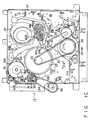
scan type cylinder 37 having magnetic heads (not shown) is rotatably coupled tomain chassis 10 mentioned above. Around thiscylinder 37, first andsecond guide holes - As is shown in Fig. 5A, first and second tape-pulling
members second guide holes cylinder 37 and guideroller 41a substantially perpendicular tomain chassis 10 are provided for first tape-pullingmember 39a such that they are located side by side with reference to each other. Likewise,slanted post 40b substantially parallel tocylinder 37 and guideroller 41b substantially perpendicular tomain chassis 10 are provided for second tape-pullingmember 39b such that they are located side by side with reference to each other. - As is shown in Fig. 5B, the one-end portions of first and
second links members second links gear 44 is arranged coaxial withsecond driving gear 43b.Sectorial gear 45a formed at one end of drivinglever 45 is in mesh with half-gear 44. An intermediate point of drivinglever 45 is swingably supported bymain chassis 10 by means ofshaft 46.Pin 45b located at the other end of drivinglever 45 engages withcam groove 32f formed in second mode-switchingcam 32e, and thiscam 32e is rotated within a predetermined angular range by loadingmotor 32. Therefore, drivinglever 45 is driven by the movement of second mode-switchingcam 32e, and transmits the driving force to first and second tape-pullingmembers gear 44, first and second driving gears 43a and 43b, and first andsecond links - As is shown in Fig. 1A,
pinch roller 47, which is part of the tape-driving mechanism, is arranged onmain chassis 10 such that it is located in the neighborhood ofcapstan shaft 28 mentioned above. Pinchroller 47 is swingably supported by one end ofpinch lever 48. Pinchlever 48 is swung in association with the above-mentioned mode-switching cams by a linking mechanism (not shown). As a result of the swing ofpinch lever 48,pinch roller 47 supported at one end oflever 48 is pressed againstcapstan shaft 28, with tape T interposed. - First and second mode-switching
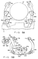
cams motor 32, and their angles of rotation are determined in accordance with the operation modes of the VTR. As is shown in Fig. 6, loadingmotor 32 is driven bymotor driver 65 under the control ofcontroller 66. In accordance with the user's operation ofcontrol panel 67,controller 66 determines an operation mode of the VTR.Controller 66 causes the mode-switching cams to be rotated by the angle corresponding to the determined operation mode. Further,controller 66 controls motordriver 68 in accordance with the determined operation mode, to thereby drivecapstan motor 27. The torque ofcapstan motor 27 is selectively transmitted tocapstan shaft 28, reel base 14 located on the tape supply side,reel base 15 located on the tape rewind side, etc. Still further,controller 66 controls motordriver 69 in accordance with the determined operation mode, to thereby drivecylinder motor 70 to rotatecylinder 37. - A description will now be given of a tape-loading mechanism of the present invention applied to the VTR of the above construction. As is shown in Figs. 5A and 5B, the tape-loading mechanism of the first embodiment of the invention has holding
members members members second guide holes main chassis 10.Tape control portions members - The holding
members tape control portions tape control portions side facing cylinder 37 on holdingmembers tape control portions members flanges portions guide rollers - With this construction, even if tape T slackens when it is pulled out of tape cassette C and set in engagement with both the
slanted posts 40a, 40b and guiderollers members tape control portions portions guide rollers tape control portions lower flanges guide rollers tape control portions portions - In the tape-loading mechanism mentioned above,
tape control portions guide rollers tape control portions posts 40a and 40b thanguide rollers tape control portions guide rollers guide rollers - Figs. 8A and 8B are views of
tape control portions tape control portions respective guide rollers member 39a is shown in Figs. 8A and 8B, for simplicity. As for the construction including second tape-pullingmember 39b, the corresponding parts are denoted by the reference numerals enclosed within the parentheses. - Referring to Figs. 8A and 8B,
tape control portion 72a corresponding to first tape-pullingmember 39a is integral with holdingmember 71a. To be more precise,tape control portion 72a is constituted by the upper surface of holdingmember 71a. In the first embodiment mentioned above,tape control section 72a is located only on one side ofguide roller 41a, whereas in the second embodiment, it is constituted by the entire upper surface of holdingmember 71a and is located on both sides ofguide roller 41a. At a position located away fromguide roller 41a by a predetermined distance,projection 75a used for guiding tape T is formed on the surface of holdingmember 71a, i.e., ontape control portion 72a. - Holding
member 71b corresponding to second tape-pullingmember 39b hastape control portion 72b andprojection 75b, which have similar constructions totape control portion 72a andprojection 75a mentioned above. - With this construction, even if tape T slackens when it is pulled out of tape cassette C and set in engagement with both the
slanted posts 40a, 40b and guiderollers members tape control portions T contacts projections tape control portions projections portions guide rollers tape control portions lower flanges guide rollers flanges tape control portions portions - Fig. 9 is a view of
tape control portions tape control portions respective guide rollers member 39a is shown in Figs. 8A and 8B, for simplicity. As for the construction including second tape-pullingmember 39b, the corresponding parts are denoted by the reference numerals enclosed within the parentheses. - Referring to Fig. 9,
tape control portion 72a corresponding to first tape-pullingmember 39a is integral with holdingmember 71a. To be more precise,tape control portion 72a is constituted by the upper surface of holdingmember 71a. Slanted portion 76a, which is slanted at a predetermined angle and serves to guide slack of tape T, is formed at that end oftape control portion 72a (i.e., holdingmember 71a ) which is located opposite to guideroller 41a. Holdingmember 71b corresponding to second tape-pullingmember 39b hastape control section 72b and slantedportion 76b similar to those mentioned above. - With this construction, even if tape T slackens when it is pulled out of tape cassette C and set in engagement with both the
slanted posts 40a, 40b and guiderollers members tape control portions portions 76a and 76b, while being controlled bytape control portions portions portions guide rollers tape control portions lower flanges guide rollers flanges tape control portions portions - According to the present invention, if tape T pulled out by first and second tape-pulling
members tape control portions portions guide rollers projections slanted portions 76a and 76b) are provided for holdingmembers portions guide rollers projections slanted portions 76a and 76b) and is therefore prevented from undesirably contacting the neighboring structural components. Accordingly, tape T is prevented from being damaged even if it slackens much. - The above embodiments were described, referring to the case where the present invention is applied to a VTR. However, the present invention is not limited to this. It can be applied to various types of magnetic recording/reproducing apparatuses, and similar advantages to those mentioned above can be expected in such application as well.
Claims (8)
- A tape-loading mechanism for pulling a tape (T) out of a tape cassette (C) and bringing the tape (T) into contact with a cylinder (37) used for recording/reproducing information on the tape (T), the mechanism comprising:
a first tape-pulling member (39a), provided on a tape inlet side of the cylinder (37) and having a first slanted post (40a) and a first guide roller (41a) thereon, for pulling the tape (T) out of the tape cassette (C), the first slanted post (40a) and the first guide roller (41a) contacting the tape (T), the first guide roller (41a) including a first tape-winding portion (73a), the tape (T) passing around the first tape-winding portion (73a) when the tape (T) contacts the first guide roller (41a);
first guide means (38a), provided on the tape inlet side of the cylinder (37), for guiding the first tape-pulling member (39a) between first and second positions, the first slanted post (40a) and the first guide roller (41a) of the first tape pulling member (39a) initially contacting the tape (T) contained in the tape cassette (C) at the first position, and the first tape-pulling member (39a) bringing the tape (T) pulled out of the tape cassette (C) into contact with the cylinder (37) at the second position;
a first holding member (71a) for holding, at the second position, the first tape-pulling member (39a) guided from the first position by the first guide means (38a);
a second tape-pulling member (39b), provided on a tape outlet side of the cylinder (37) and having a second slanted post (40b) and a second guide roller (41b) thereon, for pulling the tape (T) out of the tape cassette (C), the second slanted post (40b) and the second guide roller (41b) contacting the tape (T), the second guide roller (41b) including a second tape-winding portion (73b), the tape (T) passing around the second tape-winding portion (73b) when the tape (T) contacts the second guide roller (41b);
second guide means (38b), provided on the tape outlet side of the cylinder (37), for guiding the second tape-pulling member (39b) between third and fourth positions, the second slanted post (40b) and the second guide roller (41b) of the second tape-pulling member (39b) initially contacting the tape (T) contained in the tape cassette (C) at the third position, and the second tape-pulling member (39b) bringing the tape (T) pulled out of the tape cassette (C) into contact with the cylinder (37) at the fourth position; and
a second holding member (71b) for holding, at the fourth position, the second tape-pulling member (39b) guided from the third position by the second guide means (38b), characterized by further comprising:
first damage preventing means (72a), formed on the first holding member (71a) such that the first damage preventing means (72a) is positioned relative to at least one of a tape inlet and tape outlet side of the first guide roller (41a) of the first tape-pulling member (39a), for preventing the tape (T) from being damaged when the tape (T) falls off of the first guide roller (41a) in a slackened state, the first damage preventing means (72a) supporting only a lower edge of the tape (T) at a level corresponding to a lower end of the first tape-winding portion (73a) of the first guide roller (41a), leaving the other edge and surfaces of the tape (T) unsupported, so that should the tape (T) in a slackened state leave the first guide roller (41a), the lower edge of the slackened tape (T) will rest upon the first damage preventing means (72a); and
second damage preventing means (72b), formed on the second holding member (71b) such that the second damage preventing means (72b) is positioned relative to at least one of a tape inlet and tape outlet side of the second guide roller (41b) of the second tape-pulling member (39b), for preventing the tape (T) from being damaged when the tape (T) falls off of the second guide roller (41b) in a slackened state, the second damage preventing means (72b) supporting only the lower edge of the tape (T) at a level corresponding to a lower end of the second tape-winding portion (73b) of the second guide roller (41b), leaving the other edge and surfaces of the tape (T) unsupported, so that should the tape (T) in a slackened state leave the second guide roller (41b), the lower edge of the slackened tape (T) will rest upon the second damage preventing means (72b). - The tape-loading mechanism according to claim 1, characterized in that:
said guide rollers (41a, 41b) include flanges (74a, 74b) which define lower ends of the tape-winding portions (73a, 73b); and
said first and second damage preventing means (72a, 72b) are substantially at the same level as the flanges (74a, 74b). - The tape-loading mechanism according to claim 1, characterized in that:
said guide rollers (41a, 41b) include flanges (74a, 74b) which define lower ends of the tape-winding portions (73a, 73b); and
said first and second damage preventing means (72a, 72b) are at a slightly lower level than that of the flanges (74a, 74b). - The tape-loading mechanism according to any one of claims 1 to 3, characterized in that said first and second damage preventing means (72a, 72b) have tip ends extending in such a manner as to intersect a tape path.
- The tape-loading mechanism according to any one of claims 1 to 3, characterized in that said first and second damage preventing means (72a, 72b) are integral with the first and second holding members (71a, 71b) and are constituted by upper surfaces of the first and second holding members (71a, 71b).
- The tape-loading mechanism according to claim 5, characterized in that said first and second damage preventing means (72a, 72b) include tape guide portions, located at a position away from the guide rollers (41a, 41b) by a predetermined distance, for guiding slack of the tape.
- The tape-loading mechanism according to claim 6, characterized in that said tape guide portions include projections (75a, 75b) for guiding the slack of the tape, said projections being formed at those ends of the first and second damage preventing means (72a, 72b) which are located opposite to the guide rollers (41a, 41b).
- The tape-loading mechanism according to claim 6, characterized in that said tape guide portions include slanted portions (76a, 76b) for guiding the slack of the tape, said slanted portions being formed at those ends of the first and second damage preventing means (72a, 72b) which are located opposite to the guide rollers (41a, 41b).
Applications Claiming Priority (2)
| Application Number | Priority Date | Filing Date | Title |
|---|---|---|---|
| JP63333589A JP2675602B2 (en) | 1988-12-28 | 1988-12-28 | Tape loading device |
| JP333589/88 | 1988-12-28 |
Publications (3)
| Publication Number | Publication Date |
|---|---|
| EP0376242A2 EP0376242A2 (en) | 1990-07-04 |
| EP0376242A3 EP0376242A3 (en) | 1991-09-11 |
| EP0376242B1 true EP0376242B1 (en) | 1994-08-17 |
Family
ID=18267733
Family Applications (1)
| Application Number | Title | Priority Date | Filing Date |
|---|---|---|---|
| EP89123933A Expired - Lifetime EP0376242B1 (en) | 1988-12-28 | 1989-12-27 | Tape-loading mechanism for use in magnetic recording/reproducing apparatus |
Country Status (4)
| Country | Link |
|---|---|
| EP (1) | EP0376242B1 (en) |
| JP (1) | JP2675602B2 (en) |
| KR (1) | KR930009656B1 (en) |
| DE (1) | DE68917575T2 (en) |
Families Citing this family (1)
| Publication number | Priority date | Publication date | Assignee | Title |
|---|---|---|---|---|
| US5801898A (en) * | 1995-04-10 | 1998-09-01 | Sanyo Electric Co., Ltd. | Loading mechanism of magnetic recording-reproduction apparatus and method of assembling the mechanism |
Family Cites Families (4)
| Publication number | Priority date | Publication date | Assignee | Title |
|---|---|---|---|---|
| US4138699A (en) * | 1976-06-04 | 1979-02-06 | Victor Company Of Japan, Ltd. | Automatic tape loading type recording and/or reproducing apparatus |
| DE3509176A1 (en) * | 1985-03-14 | 1986-09-18 | Grundig E.M.V. Elektro-Mechanische Versuchsanstalt Max Grundig holländ. Stiftung & Co KG, 8510 Fürth | DEVICE FOR GUIDING A MAGNETIC TAPE IN A VIDEO RECORDER |
| DE3545964A1 (en) * | 1985-12-23 | 1987-06-25 | Grundig Emv | DEVICE FOR HOLDING A TAPE GUIDE IN A VIDEO MAGNETIC TAPE |
| JPS6424544U (en) * | 1987-08-05 | 1989-02-09 |
-
1988
- 1988-12-28 JP JP63333589A patent/JP2675602B2/en not_active Expired - Lifetime
-
1989
- 1989-12-27 DE DE68917575T patent/DE68917575T2/en not_active Expired - Fee Related
- 1989-12-27 EP EP89123933A patent/EP0376242B1/en not_active Expired - Lifetime
- 1989-12-28 KR KR1019890020622A patent/KR930009656B1/en not_active IP Right Cessation
Also Published As
| Publication number | Publication date |
|---|---|
| JP2675602B2 (en) | 1997-11-12 |
| DE68917575T2 (en) | 1995-01-12 |
| EP0376242A2 (en) | 1990-07-04 |
| EP0376242A3 (en) | 1991-09-11 |
| KR930009656B1 (en) | 1993-10-08 |
| DE68917575D1 (en) | 1994-09-22 |
| JPH02177156A (en) | 1990-07-10 |
| KR900010718A (en) | 1990-07-09 |
Similar Documents
| Publication | Publication Date | Title |
|---|---|---|
| US4408236A (en) | Magnetic tape recording and/or reproducing apparatus | |
| EP0404426B1 (en) | Mode changing mechanism for tape recording and/or reproducing apparatus | |
| EP0381081B1 (en) | Cassette tape slack-preventing apparatus for use in magnetic recording/reproducing apparatus | |
| JPH0810514B2 (en) | DAT cassette loading device | |
| KR0149638B1 (en) | Magnetic recording reproducing apparatus for selective use with tape cassettes of two different sizes | |
| US5196971A (en) | Tape loading mechanism for use in magnetic recording/reproducing apparatus having tape control features for preventing damage to tape | |
| JPS6032273B2 (en) | Apparatus for recording information on or reproducing information on a tape-shaped record carrier | |
| EP0376242B1 (en) | Tape-loading mechanism for use in magnetic recording/reproducing apparatus | |
| KR0183710B1 (en) | Deck mechanism of magnetic record/reproduce apparatus | |
| US4351498A (en) | Cassette tape device | |
| EP0381058B1 (en) | Rotation transmission mechanism | |
| US4985788A (en) | Recording and reproducing apparatus | |
| EP0376268B1 (en) | Tape guide apparatus having tape posture control pole | |
| US5691858A (en) | Magnetic recording and reproducing apparatus having a single master gear and slide member | |
| US5568339A (en) | Recording and/or reproducing device operable with a plurality of different size cassettes | |
| EP0376269B1 (en) | Magnetic recording/reproducing apparatus having capstan motor | |
| EP0422642B1 (en) | Tape loading device of magnetic recording/reproducing apparatus | |
| JPH0261853A (en) | Tape recorder device | |
| EP0345739B1 (en) | Magnetic tape recording and playback apparatus | |
| US5315459A (en) | Video cassette recorder device | |
| JP3417185B2 (en) | Recording and playback device | |
| JPS6235160Y2 (en) | ||
| JPH0695418B2 (en) | Cassette type recording / reproducing device | |
| JPH0633555Y2 (en) | Tape drive mode switching device | |
| JPS6323781Y2 (en) |
Legal Events
| Date | Code | Title | Description |
|---|---|---|---|
| PUAI | Public reference made under article 153(3) epc to a published international application that has entered the european phase |
Free format text: ORIGINAL CODE: 0009012 |
|
| 17P | Request for examination filed |
Effective date: 19900124 |
|
| AK | Designated contracting states |
Kind code of ref document: A2 Designated state(s): DE FR GB |
|
| PUAL | Search report despatched |
Free format text: ORIGINAL CODE: 0009013 |
|
| RHK1 | Main classification (correction) |
Ipc: G11B 15/665 |
|
| AK | Designated contracting states |
Kind code of ref document: A3 Designated state(s): DE FR GB |
|
| 17Q | First examination report despatched |
Effective date: 19930407 |
|
| GRAA | (expected) grant |
Free format text: ORIGINAL CODE: 0009210 |
|
| AK | Designated contracting states |
Kind code of ref document: B1 Designated state(s): DE FR GB |
|
| REF | Corresponds to: |
Ref document number: 68917575 Country of ref document: DE Date of ref document: 19940922 |
|
| ET | Fr: translation filed | ||
| PLBE | No opposition filed within time limit |
Free format text: ORIGINAL CODE: 0009261 |
|
| STAA | Information on the status of an ep patent application or granted ep patent |
Free format text: STATUS: NO OPPOSITION FILED WITHIN TIME LIMIT |
|
| 26N | No opposition filed | ||
| PGFP | Annual fee paid to national office [announced via postgrant information from national office to epo] |
Ref country code: FR Payment date: 19961211 Year of fee payment: 8 |
|
| PGFP | Annual fee paid to national office [announced via postgrant information from national office to epo] |
Ref country code: GB Payment date: 19961218 Year of fee payment: 8 |
|
| PGFP | Annual fee paid to national office [announced via postgrant information from national office to epo] |
Ref country code: DE Payment date: 19970107 Year of fee payment: 8 |
|
| PG25 | Lapsed in a contracting state [announced via postgrant information from national office to epo] |
Ref country code: GB Free format text: LAPSE BECAUSE OF NON-PAYMENT OF DUE FEES Effective date: 19971227 |
|
| PG25 | Lapsed in a contracting state [announced via postgrant information from national office to epo] |
Ref country code: FR Free format text: THE PATENT HAS BEEN ANNULLED BY A DECISION OF A NATIONAL AUTHORITY Effective date: 19971231 |
|
| GBPC | Gb: european patent ceased through non-payment of renewal fee |
Effective date: 19971227 |
|
| PG25 | Lapsed in a contracting state [announced via postgrant information from national office to epo] |
Ref country code: DE Free format text: LAPSE BECAUSE OF NON-PAYMENT OF DUE FEES Effective date: 19980901 |
|
| REG | Reference to a national code |
Ref country code: FR Ref legal event code: ST |