EP0186984A2 - Hydraulischer Stossdämpfer - Google Patents
Hydraulischer Stossdämpfer Download PDFInfo
- Publication number
- EP0186984A2 EP0186984A2 EP85308890A EP85308890A EP0186984A2 EP 0186984 A2 EP0186984 A2 EP 0186984A2 EP 85308890 A EP85308890 A EP 85308890A EP 85308890 A EP85308890 A EP 85308890A EP 0186984 A2 EP0186984 A2 EP 0186984A2
- Authority
- EP
- European Patent Office
- Prior art keywords
- piston rod
- hollow piston
- hollow
- dress cap
- cap
- Prior art date
- Legal status (The legal status is an assumption and is not a legal conclusion. Google has not performed a legal analysis and makes no representation as to the accuracy of the status listed.)
- Granted
Links
Images

Classifications
-
- B—PERFORMING OPERATIONS; TRANSPORTING
- B60—VEHICLES IN GENERAL
- B60G—VEHICLE SUSPENSION ARRANGEMENTS
- B60G17/00—Resilient suspensions having means for adjusting the spring or vibration-damper characteristics, for regulating the distance between a supporting surface and a sprung part of vehicle or for locking suspension during use to meet varying vehicular or surface conditions, e.g. due to speed or load
- B60G17/015—Resilient suspensions having means for adjusting the spring or vibration-damper characteristics, for regulating the distance between a supporting surface and a sprung part of vehicle or for locking suspension during use to meet varying vehicular or surface conditions, e.g. due to speed or load the regulating means comprising electric or electronic elements
- B60G17/0152—Resilient suspensions having means for adjusting the spring or vibration-damper characteristics, for regulating the distance between a supporting surface and a sprung part of vehicle or for locking suspension during use to meet varying vehicular or surface conditions, e.g. due to speed or load the regulating means comprising electric or electronic elements characterised by the action on a particular type of suspension unit
-
- F—MECHANICAL ENGINEERING; LIGHTING; HEATING; WEAPONS; BLASTING
- F16—ENGINEERING ELEMENTS AND UNITS; GENERAL MEASURES FOR PRODUCING AND MAINTAINING EFFECTIVE FUNCTIONING OF MACHINES OR INSTALLATIONS; THERMAL INSULATION IN GENERAL
- F16F—SPRINGS; SHOCK-ABSORBERS; MEANS FOR DAMPING VIBRATION
- F16F9/00—Springs, vibration-dampers, shock-absorbers, or similarly-constructed movement-dampers using a fluid or the equivalent as damping medium
- F16F9/32—Details
- F16F9/44—Means on or in the damper for manual or non-automatic adjustment; such means combined with temperature correction
- F16F9/46—Means on or in the damper for manual or non-automatic adjustment; such means combined with temperature correction allowing control from a distance, i.e. location of means for control input being remote from site of valves, e.g. on damper external wall
- F16F9/463—Means on or in the damper for manual or non-automatic adjustment; such means combined with temperature correction allowing control from a distance, i.e. location of means for control input being remote from site of valves, e.g. on damper external wall characterised by electrical connections
-
- B—PERFORMING OPERATIONS; TRANSPORTING
- B60—VEHICLES IN GENERAL
- B60G—VEHICLE SUSPENSION ARRANGEMENTS
- B60G2204/00—Indexing codes related to suspensions per se or to auxiliary parts
- B60G2204/10—Mounting of suspension elements
- B60G2204/20—Mounting of accessories, e.g. pump, compressor
- B60G2204/202—Mounting of accessories, e.g. pump, compressor of cables
Definitions
- This invention relates to a hydraulic damper as specified in the preamble of claim 1, for example as disclosed in US-A-3 420 341.
- variable-damping capability involves the use of an externally mounted control means 80 for mechanically, electrically or electromechanically rotating a control rod 60 a limited amount within a hollow piston rod 50, for varying the rotary position of a valved and ported lower piston half 86.
- the present invention is utilized in the context of a hydraulic damper, in the form of a suspension strut or a shock absorber, having an electrically energizable motor or like actuator that is disposed internally of a hollow piston rod and is arranged to be selectively activated to precisely control and vary flow control orificing of the piston which strokes in an oil-filled cylinder tube to damp suspension spring action.
- a hydraulic damper in the form of a suspension strut or a shock absorber, having an electrically energizable motor or like actuator that is disposed internally of a hollow piston rod and is arranged to be selectively activated to precisely control and vary flow control orificing of the piston which strokes in an oil-filled cylinder tube to damp suspension spring action.
- an insulated bulkhead and fluid seal connects internally to the actuator and extends upwardly to a connector socket having cables that extend through an upper seal seated on the upper end of the piston rod.
- the present invention is particularly concerned with the provision of a device on the end of the piston rod to ensure that the internal electrical connections are made, the device further having the potential to provide a low profile while protecting and guiding the electrical cables of a wire harness leading from a control system.
- a hydraulic damper in accordance with the present invention is characterised by the features specified in the characterising portion of claim 1.
- the said device is in the form of a dress cap that is a one-piece moulded plastics unit having interior and exterior connections to the top end of the hollow piston rod of the damper so that it is positively locked thereon when properly installed.
- the dress cap positions and maintains the location of the electrical terminals, insulator bulkhead and seal inside the hollow piston rod. If improperly installed, the dress cap self-rejects from the open end of the piston rod. Furthermore, the dress cap maintains its profile below the top of the strut when fully mated and provides protection for the cables so that no damage will occur during installation.
- the dress cap further provides improved cable dress for a damper and protects and secures the cables after assembly to withstand forces from a wide range of vibration and shock occurring during vehicle operation.
- the dress cap is preferably pre-assembled as part of a wire harness for ease of handling and to prevent loss of parts.
- the dress cap has potentially long service life in a harsh engine compartment environment and protects the hollow piston rod from the intrusion of moisture or foreign matter.
- the invention thereby makes available a hydraulic damper having a new and improved low- profile cable dress cap which is capable of installation on the outer end of a hollow piston rod of a suspension damper, and which guides and protects electrical cables leading into an internal electric motor or like actuator within the damper, while also providing a sealing plug with positive locking features for releasable connection to the upper end of the rod.
- Such a cable dress cap can be positively and releasably mounted to a hollow piston rod for the electrical cables leading into an internal electrically energizable motor or like actuator within the damper so that the outer configuration of the suspension strut or shock absorber is not materially changed.
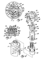
- the strut comprises a hydraulic damper with an elongate outer reservoir tube 16 closed by a lower end cap 18 and secured within a pocket provided by the bracket 12.
- the reservoir tube 16 extends upwardly from the bracket to a terminal end cap (seal cover) 20 welded to the upper end of the reservoir tube.
- the strut contains an elongate oil-filled cylinder tube 22 which is spaced inwardly from and concentric with the reservoir tube 16 and in which a piston assembly 24 with adjustable valving is mounted for stroking movements.
- a hollow piston rod 26 attached at its inner end to the piston assembly 24 extends upwardly therefrom through a rod guide 28 mounted on the upper end of the cylinder tube 22 and held in position by the end cap 20.
- An annular elastomeric seal 30 is mounted in the rod guide 28 and has annular sealing contact with the piston rod 26 to prevent loss of hydraulic shock absorber oil from the unit as the piston strokes in the cylinder tube during damping operation.
- a base valve 32 secured to the lower end of the cylinder tube controls the flow of shock absorber oil between the cylinder tube and a fluid reservoir 34 formed between the cylinder tube and the reservoir tube on compression and rebound strokes of the piston for damping action of the suspension spring provided by this unit.
- the hollow piston rod 26 has a reduced-diameter upper end 35 which carries a metallic connector 36 with an upper flange that is embedded in a toroidal elastomeric isolator cushion 38 of an upper mount assembly 40.
- This cushion 38 has a low spring rate to dissipate vibratory energy which would otherwise enter the vehicle from the piston assembly 24 as it reciprocates in the cylinder tube to damp suspension spring action.
- a metallic shell or housing 42 and cover plate 44 partially enclose the isolator cushion 38, as shown in Figure 1.
- a nut 45 is threaded on to the reduced-diameter and correspondingly threaded upper end 46 of the hollow piston rod 26 to secure the upper mount assembly to the piston rod. Threaded fasteners, not shown, conventionally secure the upper mount assembly to the sheet metal of a mounting tower or other support formed in the body of the vehicle.
- a compliant cover plate assembly 50 including a cylindrical jounce bumper 54 of a suitable elastomeric material is secured to an upper end of the hollow piston rod 26 immediately below the upper mount assembly 40. In jounce, this bumper is contacted and deflected by a bumper plate 56 that is welded to the top of the end cap 20 of the hydraulic damper.
- the compliant cover plate assembly also includes a cup-shaped connector plate 57 of sheet metal having an inner diameter embedded in the jounce bumper and an outer diameter welded to the upper end of the cylindrical steel dust tube 58. The dust tube extends from upper attachment with the plate 57 down and around the reservoir tube in conventional manner.
- the strut 10 has an air suspension spring provided by a cylindrical elastomeric air sleeve 60 having its inner, upper end connected to the upper end of the reservoir tube 16 by a constricted clamping ring 62. From this clamping ring the sleeve 60 follows downwardly around the outer periphery of the reservoir tube and is reversely curved intermediate the ends thereof to form a rolling lobe 63. From this lobe, the sleeve extends upwardly and around the lower end of the dust tube 58. A second clamping ring 64 similar to the clamping ring 62 is employed to secure the sleeve to the lower end of the dust tube in an airtight manner.
- the pneumatic chamber 66 formed by the dust tube, the reservoir tube, the elastomeric air sleeve and the compliant cover plate assembly is charged with pressurized air or other gas to provide a pneumatic suspension spring for vehicle suspension purposes.
- One system for controlling the pressure within the air spring may be based on the system disclosed in US-A-3 372 919.
- an air sleeve guide 70 which is releasably attached to the lower end of the dust tube 58.
- This guide is a resilient wide torus (ring) of plastics material which has a smooth exterior surface and low-friction engagement with the elastomeric air sleeve 60 to reduce sleeve wear during operation of the strut.
- the ring-like guide is formed with a central external groove which fits into the outwardly flanged lower end of the dust tube, as shown in Figure 1.
- the jounce bumper 54 is bonded at its internal diameter to a generally cylindrical steel insert (jounce bumper stop) 74 which fits over the shoulder 76 provided by the reduced-diameter upper end portion of the hollow piston rod 26.
- This insert (stop) 74 contacts the lower end of the connector 36 and has an inner annular groove therein which receives an elastomeric O-ring 78 that forms a static seal which sealingly engages the piston rod 26 to prevent air leakage past the jounce bumper.
- the jounce bumper 54 has a downwardly extending skirt 80 with convolutions that terminate in a lower annular end surface 82. On jounce, the bumper skirt 80 is deflected as the contact plate 56 engages the end surface 82 and moves towards the jounce bumper stop 74.
- the cover plate assembly 50 forms a compliant upper end and seal for the air spring provided by the pressurized pneumatic chamber 66.
- a collar-like upper end 88 of the jounce bumper assembly 54 has an end surface that seats against the lower surface 90 of the metallic shell 42 of the upper mount assembly 40.
- the piston rod 26 is connected to the isolator cushion 38 so that hydraulic forces generated by the piston as it strokes in the cylinder tube of the strut will be primarily routed to and dissipated by the isolator cushion 38, which preferably has a lower spring rate than that of the jounce bumper 54.
- This substantially reduces the transmittal of road shocks by the piston rod to the passenger compartment of the vehicle, so materially contributing to the comfort of the operator and the passengers therein.
- the suspension spring loads from the air sleeve will be carried through the higher spring rate jounce bumper 54 to the shell-like housing 42 of the upper mount assembly.
- the piston assembly 24 provides selective damping rates and preferably has variable deflected- disc valving with flow control orifices therein whose flow size openings can be varied to control the damping characteristics of the strut.
- This variable- orifice construction is preferably like that disclosed in EP-A-85 30 5781.8.
- this valving comprises an orifice plate 94 fixed in the piston shell with flow openings therethrough.
- a selector plate 98 which is rotatable to any number of positions to control the size of the openings and the flow through the piston for deflection of discs mounted beneath the orifice plate, as described in the said EP-A-85 30 5781.8.
- the rotational movement of the selector plate is controlled by an actuator 102 fixed at a predetermined position entirely within the hollow piston rod 26.
- a hollow connector tube 101 extends from the actuator 102 within the piston rod 26, and is pinned or otherwise connected to the upstanding neck portion 103 of the piston assembly 24 extending therein, as shown in Figure 1. With such connection, high-pressure damper fluid is present in the hollow piston rod, such that effective fluid sealing of the piston rod, preferably at the upper end thereof, is necessary.
- the actuator 102 has a rotatable output shaft 104 which extends through the connector tube 101 into driving connection with the rotatable selector plate 98 and is operative to rotate the selector plate to appropriate positions to control the rebound damping characteristics of the strut.
- the amount of selector plate rotation is a control function that can be manually selected by the operator or automatically selected by computer control in accordance with road conditions.
- the upper end of the actuator 102 has a reduced-diameter end portion 106 which has four female terminals 108 for conducting electrical energy into the actuator 102 for operation thereof.
- the terminals 108 receive the male terminals 110 of a cylindrical support socket 111 formed at the lower end of an elongate insulated bulkhead 114.
- the socket 111 has a keyway 112 in the wall thereof which fits on a key 113 on the upper end of the actuator 102 to mechanically interlock the actuator to the bulkhead 114.
- the bulkhead 114 is preferably moulded from glass-reinforced polyester material and is fully compatible with high-temperature damper oils and pressures and other internal environmental forces of the strut. From the plug end, the bulkhead 114 has an elongate stem 116 of a reduced diameter to fit into the reduced-diameter end 35 of the piston rod. The upper end of the stem 116 has an annular groove 118 which carries a pair of O-rings 120. These O-rings are sealingly engaged with the inner wall of the reduced-diameter end 35 of the hollow piston rod, to provide high-pressure sealing of the damper oil.
- the upper terminals 124 which bus to the four lower terminals 110.
- the upper terminals 124 project towards the upper ends of the piston rod, and fit into female terminals 126 of a cylindrical socket 128 that slip-fits in a plug-like fashion into the upper end of the piston rod, as shown in Figures 3 and 5.
- the upper end of the strut bulkhead has a pair of steel, upwardly-projecting locator pins 130 that fit into longitudinally extending grooves 132 moulded into the peripheral surface of the socket 128. These pins interlock with and orient the socket 128 relative to the bulkhead 114, and ensure the electrical connection of these two parts, as is best illustrated in Figure 3.
- the female terminals 126 are electrically connected to three electrical cables 134 that project upwardly therefrom through the top of the socket 128 and then through cable sealing holes 138 in an upper cylindrical seal 140.
- the seal 140 is moulded from a self-lubricating silicone material, and has a plurality of sealing ribs 142 which contact the inner diameter of the piston rod 26 to effectively block the entry of any moisture or any contaminants to the socket 128 and the hollow piston rod.
- the cables 134 After passing through the cable sealing holes, the cables 134 are turned through one of a plurality of horizontally aligned groove-like U-shaped cuts 144 formed in the threaded upper end 46 of the piston rod 26.
- the cables are retained in this location by the installation of a dress cap (a cable dress cap) 146 which locks on the threaded upper end 46 of the piston rod 26 as will be later described. From the dress cap, the cables are circled on top of the cover plate 44 and are retained in such position by arcuately arranged tabs 150 of a cable retainer 152.
- the cables lead under a sheet metal outer plate 153 tabbed to the cover plate 44 and extend downwardly along the dust tube 58 and under a retaining strap 156, fastened around the dust tube, to a terminal end plug 160.
- This plug 160 is operatively connected to a source of electrical energy and controls 161, which may comprise a computer control system, and in response to road signals received from such a computer control system the actuator 102 will be energized to rotate the output shaft 104 and thereby turn the selector plate of the valving within the shock absorber piston 24 to select a damping rate which matches road conditions automatically.
- the dress cap 146 is moulded from nylon (polyamide) or other suitable plastics or like material, and has a pair of inner arcuate retainer walls 162, 164 which plug into and close the open threaded upper end 46 of the hollow piston rod 26.
- the walls 162, 164 extend downwardly from the circular centre of an upper bridge 165.
- the bridge has a pair of cable hold-down bars 166, which are of generally inverted U-shape as seen in cross-section, extending diametrically across the top of the cap to protect the cable. The cable is thus led radially from the circular centre to fit into the U-shaped cuts 144 in the threaded upper end portion 46 of the piston rod 26.
- the top of these bars 166 connects to an outer peripheral wall (skirt) 168 which has identical locking tabs 170, 172 integrally formed therein diametrically opposed to one another and disposed at an angle of 90° with respect to the hold-down bars 166.
- the locking tabs extend upwardly and are spring fingers that have inwardly extending locking projections 174, 176 which are formed on the upper ends thereof and releasably lock within diametrically opposed openings (keepers) 180, 182 in the piston rod.
- keepers diametrically opposed openings
- the seal 140 When the dress cap 146 is pressed into the positive-lock position, the seal 140 is forced downwardly so that the cylindrical socket 128 is fully engaged with the terminals of the insulated bulkhead 114. If the plug constituted by the cylindrical socket 128 is not properly connected or the seal 140 is not in a proper sealing position, the cap locking projections 174, 176 will not reach the openings 180, 182 and the cap will self-reject. The installer can then effect proper re-assembly of the plug and seal to lock the cap in place.
- the cables 134 pass through one of the opposing end openings 185, 187 provided by lower bars 189 interconnecting bottom portions of the skirt 168, as is seen in Figures 4 and 6.
- the dress cap 146 provides guidance for the electric cables 134 of a wire harness and when fully installed on the upper end 46 of the hollow piston rod 26 ensures that the seal 140 is in its proper sealing position and that the plug-type socket 128 makes the necessary electrical connection with the terminals 124.
- the dress cap which potentially has a low profile, is effective to position and maintain terminals, connectors and fluid seals within the hollow piston rod while providing effective routing and protection of electrical cables leading to the internally mounted electric actuator.
- the insulated bulkhead 114 in the context of a hydraulic damper, and as optional features also the cylindrical socket 128 and the upper cylindrical seal 140, from the subject of EP-A-of even date, based on USSN 685,857.
Landscapes
- Engineering & Computer Science (AREA)
- General Engineering & Computer Science (AREA)
- Mechanical Engineering (AREA)
- Vehicle Body Suspensions (AREA)
- Fluid-Damping Devices (AREA)
Applications Claiming Priority (2)
| Application Number | Priority Date | Filing Date | Title |
|---|---|---|---|
| US06/685,460 US4660688A (en) | 1984-12-24 | 1984-12-24 | Adaptive ride hydraulic damper with piston rod dress cap |
| US685460 | 1984-12-24 |
Publications (3)
| Publication Number | Publication Date |
|---|---|
| EP0186984A2 true EP0186984A2 (de) | 1986-07-09 |
| EP0186984A3 EP0186984A3 (en) | 1987-08-19 |
| EP0186984B1 EP0186984B1 (de) | 1989-06-14 |
Family
ID=24752295
Family Applications (1)
| Application Number | Title | Priority Date | Filing Date |
|---|---|---|---|
| EP85308890A Expired EP0186984B1 (de) | 1984-12-24 | 1985-12-06 | Hydraulischer Stossdämpfer |
Country Status (4)
| Country | Link |
|---|---|
| US (1) | US4660688A (de) |
| EP (1) | EP0186984B1 (de) |
| CA (1) | CA1246100A (de) |
| DE (1) | DE3571069D1 (de) |
Cited By (5)
| Publication number | Priority date | Publication date | Assignee | Title |
|---|---|---|---|---|
| DE3833891A1 (de) * | 1987-10-05 | 1989-05-18 | Monroe Auto Equipment Co | Stossdaempfer |
| US5726152A (en) * | 1990-09-21 | 1998-03-10 | Merck & Co., Inc. | Vascular endothelial cell growth factor II |
| DE102006059297A1 (de) * | 2006-12-15 | 2008-06-19 | Bayerische Motoren Werke Ag | Schwingungsdämpfer |
| IT202200010937A1 (it) * | 2022-05-25 | 2023-11-25 | Fca Italy Spa | "Gruppo ammortizzatore per una sospensione di autoveicolo" |
| IT202200010946A1 (it) * | 2022-05-25 | 2023-11-25 | Fca Italy Spa | "Gruppo ammortizzatore per una sospensione di autoveicolo" |
Families Citing this family (30)
| Publication number | Priority date | Publication date | Assignee | Title |
|---|---|---|---|---|
| CA1263414A (en) * | 1986-06-05 | 1989-11-28 | Magnus Lizell | Restriction valve device for hydraulic pressure fluids in vehicle shock absorbing mechanisms |
| US5217095A (en) * | 1986-06-05 | 1993-06-08 | Monroe Auto Equipment Company | Method and apparatus for absorbing mechanical shock |
| US4875560A (en) * | 1986-09-19 | 1989-10-24 | Tokico Ltd. | Damping force adjustable hydraulic shock absorber |
| US5090524A (en) * | 1987-10-05 | 1992-02-25 | Monroe Auto Equipment Company | Shock absorber with an electrical connector |
| US4890858A (en) * | 1988-02-16 | 1990-01-02 | Monroe Auto Equipment Company | Method and apparatus for controlling shock absorbers |
| US4867475A (en) * | 1988-02-16 | 1989-09-19 | Monroe Auto Equipment Company | Method and apparatus for controlling shock absorbers |
| US4955460A (en) * | 1988-08-01 | 1990-09-11 | Monroe Auto Equipment Company | Control valve for shock absorbers |
| US5363945A (en) * | 1988-08-01 | 1994-11-15 | Monroe Auto Equipment Company | Control valve for shock absorbers |
| US5211268A (en) * | 1988-08-01 | 1993-05-18 | Monroe Auto Equipment Company | Control valve for shock absorbers |
| GB2300893B (en) * | 1995-05-19 | 1999-06-09 | Monroe Auto Equipment Co | Method and apparatus for delivering fluid and/or electric signals |
| US6592136B2 (en) | 2001-07-02 | 2003-07-15 | Fox Factory, Inc. | Bicycle fork cartridge assembly |
| US7128192B2 (en) | 2001-08-30 | 2006-10-31 | Fox Factory, Inc. | Inertia valve shock absorber |
| US7273137B2 (en) * | 2001-08-30 | 2007-09-25 | Fox Factory, Inc. | Inertia valve shock absorber |
| US7703585B2 (en) * | 2002-06-25 | 2010-04-27 | Fox Factory, Inc. | Integrated and self-contained suspension assembly having an on-the-fly adjustable air spring |
| US20080296814A1 (en) | 2002-06-25 | 2008-12-04 | Joseph Franklin | Gas spring with travel control |
| US10941828B2 (en) | 2002-06-25 | 2021-03-09 | Fox Factory, Inc. | Gas spring with travel control |
| US8464850B2 (en) | 2006-11-16 | 2013-06-18 | Fox Factory, Inc. | Gas spring curve control in an adjustable-volume gas-pressurized device |
| US7963509B2 (en) | 2007-01-31 | 2011-06-21 | Fox Factory, Inc. | Travel control for a gas spring and gas spring having very short travel modes |
| DE102004024522A1 (de) * | 2004-05-18 | 2005-12-15 | Dr.Ing.H.C. F. Porsche Ag | Transportschutz für Kabelenden an Federbeinen |
| US7699146B1 (en) | 2006-04-02 | 2010-04-20 | Fox Factory, Inc. | Suspension damper having inertia valve and user adjustable pressure-relief |
| US7900755B2 (en) * | 2007-09-28 | 2011-03-08 | GM Global Technology Operations LLC | Bi-fold valve-type magnetorheological fluid energy absorbing device |
| US9371883B2 (en) * | 2011-07-28 | 2016-06-21 | Robert H. Wehr | Inertial terrain transit event manager apparatus |
| DE102012016437B4 (de) * | 2012-08-18 | 2019-11-14 | Audi Ag | Schwingungsdämpfer für ein Kraftfahrzeug |
| US8991841B2 (en) | 2012-09-04 | 2015-03-31 | Msi Defense Solutions, Llc | Air spring, air strut and air suspension system with a linearized spring rate |
| DE102012215716B4 (de) * | 2012-09-05 | 2025-02-20 | Bayerische Motoren Werke Aktiengesellschaft | Abstützung eines eine Steuer- und/oder Versorgungsleitung aufweisenden Schwingungsdämpfers |
| DE102015203009B4 (de) | 2015-02-19 | 2021-03-18 | Zf Friedrichshafen Ag | Kolbenstangen-Zylinderaggregat mit einer Leitung |
| KR102614823B1 (ko) * | 2016-12-13 | 2023-12-18 | 에이치엘만도 주식회사 | 와이어 커넥터 및 이를 갖는 댐퍼용 피스톤 조립체 |
| DE102017221647A1 (de) * | 2017-12-01 | 2019-06-06 | Volkswagen Aktiengesellschaft | Kontaktierungseinrichtung für ein innerhalb eines Schwingungsdämpfers angeordnetes elektrisch ansteuerbares Ventil |
| JP7378881B2 (ja) * | 2019-08-05 | 2023-11-14 | カヤバモーターサイクルサスペンション株式会社 | フロントフォーク |
| DE102019215995A1 (de) * | 2019-10-17 | 2021-04-22 | Zf Friedrichshafen Ag | Kolbenstange für Kolbenzylinder-Aggregat mit einer internen Leitung |
Family Cites Families (13)
| Publication number | Priority date | Publication date | Assignee | Title |
|---|---|---|---|---|
| US1378195A (en) * | 1915-08-19 | 1921-05-17 | Jr Charles W James | Pipe-cap for electric conduits |
| US1294155A (en) * | 1917-03-07 | 1919-02-11 | James C Phelps | Outlet device for conduits. |
| US1381073A (en) * | 1917-10-16 | 1921-06-07 | Frederick I Johnson | Conduit-end protector |
| US2573600A (en) * | 1948-12-17 | 1951-10-30 | Gen Electric | Strain relief bushing |
| US3231300A (en) * | 1961-12-22 | 1966-01-25 | Ford Motor Co | Connecting means |
| US3827538A (en) * | 1966-11-09 | 1974-08-06 | F Morgan | Shock absorbers |
| US3420341A (en) * | 1967-10-16 | 1969-01-07 | Jonathan N Keehn | Variable shock absorber |
| JPS5922329B2 (ja) * | 1976-06-21 | 1984-05-25 | 株式会社ニフコ | コ−ド留め具 |
| US4185509A (en) * | 1976-09-10 | 1980-01-29 | Textron Inc. | Traction-drive transmission |
| JPS53117170A (en) * | 1977-03-22 | 1978-10-13 | Honda Motor Co Ltd | Regulator of damping force changing mechanism for rolling stock |
| DE2911768C2 (de) * | 1979-03-26 | 1983-01-20 | F & O Electronic Systems GmbH & Co, 6901 Neckarsteinach | Regelbarer Stoßdämpfer, insbesondere für Kraftfahrzeuge |
| US4527676A (en) * | 1982-02-13 | 1985-07-09 | Atsugi Motor Parts Co., Ltd. | Variable-damping-force shock absorber |
| US4620619A (en) * | 1982-05-20 | 1986-11-04 | Atsugi Motor Parts Co., Ltd. | Variable-damping-force shock absorber |
-
1984
- 1984-12-24 US US06/685,460 patent/US4660688A/en not_active Expired - Fee Related
-
1985
- 1985-11-01 CA CA000494414A patent/CA1246100A/en not_active Expired
- 1985-12-06 EP EP85308890A patent/EP0186984B1/de not_active Expired
- 1985-12-06 DE DE8585308890T patent/DE3571069D1/de not_active Expired
Cited By (6)
| Publication number | Priority date | Publication date | Assignee | Title |
|---|---|---|---|---|
| DE3833891A1 (de) * | 1987-10-05 | 1989-05-18 | Monroe Auto Equipment Co | Stossdaempfer |
| DE3833891C2 (de) * | 1987-10-05 | 1998-07-02 | Tenneco Automotive Inc | Stoßdämpfer |
| US5726152A (en) * | 1990-09-21 | 1998-03-10 | Merck & Co., Inc. | Vascular endothelial cell growth factor II |
| DE102006059297A1 (de) * | 2006-12-15 | 2008-06-19 | Bayerische Motoren Werke Ag | Schwingungsdämpfer |
| IT202200010937A1 (it) * | 2022-05-25 | 2023-11-25 | Fca Italy Spa | "Gruppo ammortizzatore per una sospensione di autoveicolo" |
| IT202200010946A1 (it) * | 2022-05-25 | 2023-11-25 | Fca Italy Spa | "Gruppo ammortizzatore per una sospensione di autoveicolo" |
Also Published As
| Publication number | Publication date |
|---|---|
| EP0186984B1 (de) | 1989-06-14 |
| EP0186984A3 (en) | 1987-08-19 |
| US4660688A (en) | 1987-04-28 |
| CA1246100A (en) | 1988-12-06 |
| DE3571069D1 (en) | 1989-07-20 |
Similar Documents
| Publication | Publication Date | Title |
|---|---|---|
| EP0186984B1 (de) | Hydraulischer Stossdämpfer | |
| US4576258A (en) | Adaptive ride hydraulic damper | |
| EP0581476B1 (de) | Elektrorheologische Flüssigkeiten benutzende, verstellbare Dämpfer | |
| US4828232A (en) | Vehicle air suspension strut with compliant cover plate assembly | |
| JP4726161B2 (ja) | 外部案内式er減衰装置 | |
| US4711463A (en) | Vehicle suspension strut and upper mount assembly therefor | |
| US5335757A (en) | Hydraulic adjustable vibration damper | |
| US4858899A (en) | Bushing type vibration insulator | |
| US4846318A (en) | Electrical connector for shock absorbers | |
| US5649691A (en) | Shock absorber and pneumatic spring assembly | |
| EP0133347B1 (de) | Pneumatisches Aufhängungsaggregat | |
| CA1298325C (en) | Air spring damper for vehicle suspension | |
| EP0514496B1 (de) | Zündanlage für maschinen mit einem transformator und dessen einstellungsmitteln | |
| EP1219857B1 (de) | Zweirohr-Schwingungsdämpfer, gefüllt mit hydraulischer Flüssigkeit und magnetorheologischer Flüssigkeit | |
| US20020157910A1 (en) | Floating rod guide | |
| US5575360A (en) | Shock absorber assembly for a motor vehicle, the shock absorber assembly having a pneumatic spring | |
| US4665764A (en) | Rotary actuator | |
| EP0080267B1 (de) | Aus Luftfeder und Stossdämpfer gebildetes Federbein für Fahrzeuge | |
| US5839552A (en) | Method and apparatus for delivering fluid and or electric signals | |
| US10487904B2 (en) | Cylinder device | |
| US5090524A (en) | Shock absorber with an electrical connector | |
| JP7316308B2 (ja) | フロントフォーク | |
| JPH074353Y2 (ja) | 液圧機器におけるコネクタ構造 | |
| US20040155521A1 (en) | Car brake anti-lock system | |
| GB2153482A (en) | Hydraulic campers |
Legal Events
| Date | Code | Title | Description |
|---|---|---|---|
| PUAI | Public reference made under article 153(3) epc to a published international application that has entered the european phase |
Free format text: ORIGINAL CODE: 0009012 |
|
| 17P | Request for examination filed |
Effective date: 19851213 |
|
| AK | Designated contracting states |
Kind code of ref document: A2 Designated state(s): DE FR GB IT |
|
| PUAL | Search report despatched |
Free format text: ORIGINAL CODE: 0009013 |
|
| AK | Designated contracting states |
Kind code of ref document: A3 Designated state(s): DE FR GB IT |
|
| 17Q | First examination report despatched |
Effective date: 19880928 |
|
| GRAA | (expected) grant |
Free format text: ORIGINAL CODE: 0009210 |
|
| AK | Designated contracting states |
Kind code of ref document: B1 Designated state(s): DE FR GB IT |
|
| ITF | It: translation for a ep patent filed | ||
| REF | Corresponds to: |
Ref document number: 3571069 Country of ref document: DE Date of ref document: 19890720 |
|
| ET | Fr: translation filed | ||
| PG25 | Lapsed in a contracting state [announced via postgrant information from national office to epo] |
Ref country code: GB Effective date: 19891206 |
|
| PLBE | No opposition filed within time limit |
Free format text: ORIGINAL CODE: 0009261 |
|
| STAA | Information on the status of an ep patent application or granted ep patent |
Free format text: STATUS: NO OPPOSITION FILED WITHIN TIME LIMIT |
|
| 26N | No opposition filed | ||
| GBPC | Gb: european patent ceased through non-payment of renewal fee | ||
| PG25 | Lapsed in a contracting state [announced via postgrant information from national office to epo] |
Ref country code: FR Effective date: 19900831 |
|
| PG25 | Lapsed in a contracting state [announced via postgrant information from national office to epo] |
Ref country code: DE Effective date: 19900901 |
|
| REG | Reference to a national code |
Ref country code: FR Ref legal event code: ST |