EP0186841A1 - Support frame for resistor elements in a heating furnace for glass sheets - Google Patents
Support frame for resistor elements in a heating furnace for glass sheets Download PDFInfo
- Publication number
- EP0186841A1 EP0186841A1 EP85116023A EP85116023A EP0186841A1 EP 0186841 A1 EP0186841 A1 EP 0186841A1 EP 85116023 A EP85116023 A EP 85116023A EP 85116023 A EP85116023 A EP 85116023A EP 0186841 A1 EP0186841 A1 EP 0186841A1
- Authority
- EP
- European Patent Office
- Prior art keywords
- support frame
- elements
- set forth
- furnace
- resistor
- Prior art date
- Legal status (The legal status is an assumption and is not a legal conclusion. Google has not performed a legal analysis and makes no representation as to the accuracy of the status listed.)
- Granted
Links
Images


Classifications
-
- F—MECHANICAL ENGINEERING; LIGHTING; HEATING; WEAPONS; BLASTING
- F27—FURNACES; KILNS; OVENS; RETORTS
- F27D—DETAILS OR ACCESSORIES OF FURNACES, KILNS, OVENS, OR RETORTS, IN SO FAR AS THEY ARE OF KINDS OCCURRING IN MORE THAN ONE KIND OF FURNACE
- F27D1/00—Casings; Linings; Walls; Roofs
- F27D1/02—Crowns; Roofs
- F27D1/021—Suspended roofs
-
- C—CHEMISTRY; METALLURGY
- C03—GLASS; MINERAL OR SLAG WOOL
- C03B—MANUFACTURE, SHAPING, OR SUPPLEMENTARY PROCESSES
- C03B29/00—Reheating glass products for softening or fusing their surfaces; Fire-polishing; Fusing of margins
- C03B29/04—Reheating glass products for softening or fusing their surfaces; Fire-polishing; Fusing of margins in a continuous way
- C03B29/06—Reheating glass products for softening or fusing their surfaces; Fire-polishing; Fusing of margins in a continuous way with horizontal displacement of the products
- C03B29/08—Glass sheets
-
- F—MECHANICAL ENGINEERING; LIGHTING; HEATING; WEAPONS; BLASTING
- F27—FURNACES; KILNS; OVENS; RETORTS
- F27B—FURNACES, KILNS, OVENS, OR RETORTS IN GENERAL; OPEN SINTERING OR LIKE APPARATUS
- F27B9/00—Furnaces through which the charge is moved mechanically, e.g. of tunnel type; Similar furnaces in which the charge moves by gravity
- F27B9/06—Furnaces through which the charge is moved mechanically, e.g. of tunnel type; Similar furnaces in which the charge moves by gravity heated without contact between combustion gases and charge; electrically heated
- F27B9/062—Furnaces through which the charge is moved mechanically, e.g. of tunnel type; Similar furnaces in which the charge moves by gravity heated without contact between combustion gases and charge; electrically heated electrically heated
- F27B9/063—Resistor heating, e.g. with resistors also emitting IR rays
-
- H—ELECTRICITY
- H05—ELECTRIC TECHNIQUES NOT OTHERWISE PROVIDED FOR
- H05B—ELECTRIC HEATING; ELECTRIC LIGHT SOURCES NOT OTHERWISE PROVIDED FOR; CIRCUIT ARRANGEMENTS FOR ELECTRIC LIGHT SOURCES, IN GENERAL
- H05B3/00—Ohmic-resistance heating
- H05B3/62—Heating elements specially adapted for furnaces
- H05B3/64—Heating elements specially adapted for furnaces using ribbon, rod, or wire heater
Definitions
- Support frame for resistor elements in a heating furnace for glass sheets is provided.
- the present invention relates to a support frame for resistor elements in a heating furnace for glass sheets, said frame providing a substantially continuous, elongated rest surface for a resistor element.
- the available resistor element support frames are manufactured for a certain, predetermined resistor element length, a furnace being lengthwise fitted with a plurality of separate arrays of resistor elements with their support frames. A resistor cannot be replaced until a furnace is cooled which means a long down-time. There will be a large number of separate resistor elements.
- An object of the invention is to provide a novel support frame for resistor elements for eliminating the above drawbacks.
- this object is accomplished by fastening the separate support frame elements to each other by means of links.
- the support frame elements are preferably trough-like castings.
- a support frame for carrying resistor elements comprises separate support frame elements 1 with a trough-like or tubular space 2 being formed therein.
- One end of each frame element 1 is provided with a runner 3 fit for a bracket 4 at the other end of a frame element.
- Drilled in the overlapping parts of runner 3 and bracket 4 is a hole 5 which is fit for a pin 6.
- a support frame of desired length is obtained by linking successively a desired number of frame elements 1.
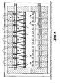
- the support frames are placed side by side in the lateral direction of a furnace so as to cover substantially the entire length of a furnace (see figs. 8 and 9).
- the support frames are mounted in suspension by means of bearing rails 7 fixed to the ends of articulated pins 6.
- the top ends of bearing rails 7 are fastened by means of a swing joint 8, which is inside the furnace, to suspension rods 9 passed through the furnace ceiling.
- the support frames are free to perform thermal expansion movement without causing mechanical stress or heat runoffs on the suspension lead-in.
- Fig. 5 shows an end element 10 for the leading end of a support frame and for effecting penetration through the end wall of a furnace.
- Said end element 10 is tubular and fitted with an attachment flange 11 for fastening to the end wall of a furnace.
- Said element 10 is further fitted with a sleeve 12 provided with a hole 5 for a hole/articulated pin joint 5, 6 with the next frame element 1.
- the articulated element structure of the invention also contributes to safety in operation.
- the articulated joint can be designed by using any prior known link or application of a prior known link.
- the frame elements of the invention have been used for overhead resistors extending lengthwise of a furnace.
- figs. 8 and 9 show the crosswise overhead and bottom resistors 1a and lengthwise bottom resistors 1b of a furnace.
- the frame elements of the invention have not been used for the latter.
Abstract
Description
- Support frame for resistor elements in a heating furnace for glass sheets.
- The present invention relates to a support frame for resistor elements in a heating furnace for glass sheets, said frame providing a substantially continuous, elongated rest surface for a resistor element. The available resistor element support frames are manufactured for a certain, predetermined resistor element length, a furnace being lengthwise fitted with a plurality of separate arrays of resistor elements with their support frames. A resistor cannot be replaced until a furnace is cooled which means a long down-time. There will be a large number of separate resistor elements.
- An object of the invention is to provide a novel support frame for resistor elements for eliminating the above drawbacks.
- According to the invention, this object is accomplished by fastening the separate support frame elements to each other by means of links. The support frame elements are preferably trough-like castings.
- This solution offers several significant advantages.
- - It is possible to cast short frame elements for easier casting.
- - The short frame elements can be assembled into long continuous support frames.
- - Inside a support frame will be formed a continuous tube or trough for inserting a resistor element therein from the end of said tube or trough.
- - Replacement of a resistor element is easy without cooling the furnace.
- - The number of separate resistor elements is substantially reduced (e.g. in a
tempering furnace 1/3 of the present number). - One embodiment of the invention will now be described in more detail with reference made to the accompanying drawings, in which
- fig. 1 shows a support frame element of the invention in side view and
- fig. 2 shows the same element in plan view.
- Fig. 3 is a cross-section of the element shown in figs. 1 and 2.
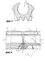
- Fig. 4 is a sectional view of a link member between the frame elements.
- Fig. 5 shows a support frame element mounted on the end of a support frame for leading through the wall of a furnace.
- Figs. 6 and 7 are side and front views respectively of the rear end member of a support frame.
- Fig. 8 is a side view of the end section of a glass tempering furnace, wherein a support frame for resistor elements of the invention is used for supporting the resistor elements mounted above the glass sheet supporting rollers.
- Fig. 9 is an end view of the tempering furnace shown in fig. 8 showing in more detail the mounting of laterally parallel support frames on the ceiling of a furnace.
- A support frame for carrying resistor elements (not shown) comprises separate
support frame elements 1 with a trough-like ortubular space 2 being formed therein. One end of eachframe element 1 is provided with arunner 3 fit for a bracket 4 at the other end of a frame element. Drilled in the overlapping parts ofrunner 3 and bracket 4 is ahole 5 which is fit for apin 6. A support frame of desired length is obtained by linking successively a desired number offrame elements 1. - The support frames are placed side by side in the lateral direction of a furnace so as to cover substantially the entire length of a furnace (see figs. 8 and 9). The support frames are mounted in suspension by means of bearing rails 7 fixed to the ends of articulated
pins 6. The top ends of bearing rails 7 are fastened by means of a swing joint 8, which is inside the furnace, tosuspension rods 9 passed through the furnace ceiling. Thus, the support frames are free to perform thermal expansion movement without causing mechanical stress or heat runoffs on the suspension lead-in. - Fig. 5 shows an
end element 10 for the leading end of a support frame and for effecting penetration through the end wall of a furnace. Saidend element 10 is tubular and fitted with anattachment flange 11 for fastening to the end wall of a furnace. Saidelement 10 is further fitted with asleeve 12 provided with ahole 5 for a hole/articulatedpin joint next frame element 1. - The rear end of a support frame, i.e. the opposite end of a furnace, is fitted by means of the hole/pin linkl4, 5, 6 with an
end member 13, which serves as an end stop for a resistor element (not shown) inserted in thetubular space 2 of a support frame. The swinging ofend member 13 is prevented by means of aprotrusion 15 whosetop surface 16 leans against the bottom surface offrame element 1. - By selecting the length of support frame elements in a manner to match the distance between the link and bearing points set between the ceramic elements of a resistor element carried by said frame, it is possible to make sure that the deformations caused by thermal expansion do not significantly change the distance between resistance wire and support frame. Hence, the articulated element structure of the invention also contributes to safety in operation.
- The invention is by no means limited to the above embodiment but, instead, the details can be modified in many ways within the scope of occupational skill and nevertheless exploiting the invention set forth in the annexed claims. For example, the articulated joint can be designed by using any prior known link or application of a prior known link. In some cases, it may be preferable to make the fastening ends of support frame elements mutually alike, which requires two types of frame elements as fas as their fastening ends are concerned.
- In the described case, the frame elements of the invention have been used for overhead resistors extending lengthwise of a furnace. In addition, figs. 8 and 9 show the crosswise overhead and bottom resistors 1a and lengthwise
bottom resistors 1b of a furnace. The frame elements of the invention have not been used for the latter.
Claims (9)
Priority Applications (1)
| Application Number | Priority Date | Filing Date | Title |
|---|---|---|---|
| AT85116023T ATE35529T1 (en) | 1985-01-03 | 1985-12-16 | SUPPORTING FRAME FOR RESISTANCE ELEMENTS IN A HEATING FURNACE FOR GLASS PLATES. |
Applications Claiming Priority (2)
| Application Number | Priority Date | Filing Date | Title |
|---|---|---|---|
| FI850025A FI72305C (en) | 1985-01-03 | 1985-01-03 | EN AVAILABLE PICTURE OF FITTINGS FOR MOTORCYCLES I EN UPPVAERMNINGSUGN FOER GLASSKIVOR. |
| FI850025 | 1985-01-03 |
Publications (2)
| Publication Number | Publication Date |
|---|---|
| EP0186841A1 true EP0186841A1 (en) | 1986-07-09 |
| EP0186841B1 EP0186841B1 (en) | 1988-07-06 |
Family
ID=8520146
Family Applications (1)
| Application Number | Title | Priority Date | Filing Date |
|---|---|---|---|
| EP85116023A Expired EP0186841B1 (en) | 1985-01-03 | 1985-12-16 | Support frame for resistor elements in a heating furnace for glass sheets |
Country Status (7)
| Country | Link |
|---|---|
| US (1) | US4712086A (en) |
| EP (1) | EP0186841B1 (en) |
| JP (1) | JPS61168201A (en) |
| CN (1) | CN1006780B (en) |
| AT (1) | ATE35529T1 (en) |
| DE (1) | DE3563609D1 (en) |
| FI (1) | FI72305C (en) |
Cited By (2)
| Publication number | Priority date | Publication date | Assignee | Title |
|---|---|---|---|---|
| FR2658499A1 (en) * | 1990-02-21 | 1991-08-23 | Saint Gobain Vitrage Int | OVEN FOR HEATING GLASS SHEETS. |
| EP0443948A1 (en) * | 1990-02-21 | 1991-08-28 | Saint-Gobain Vitrage International | Bending of glass-sheets by gravity on a bending mould |
Families Citing this family (2)
| Publication number | Priority date | Publication date | Assignee | Title |
|---|---|---|---|---|
| US5337393A (en) * | 1990-11-30 | 1994-08-09 | Glasstech, Inc. | Method for heating a flat glass sheet |
| US6236021B1 (en) * | 1998-07-01 | 2001-05-22 | Intevac, Inc. | Substrate transport assembly for rapid thermal processing system |
Citations (3)
| Publication number | Priority date | Publication date | Assignee | Title |
|---|---|---|---|---|
| GB729072A (en) * | 1951-11-27 | 1955-05-04 | Thermo Industrieofenbau G M B | Improvements relating to furnaces for heating metals, glass and ceramic materials |
| DE1948724A1 (en) * | 1969-09-26 | 1971-04-08 | Riedhammer Ludwig Gmbh | Electric heating device on tunnel ovens |
| US3818181A (en) * | 1971-11-29 | 1974-06-18 | Saint Gobain | Tunnel furnace, resistance type |
Family Cites Families (14)
| Publication number | Priority date | Publication date | Assignee | Title |
|---|---|---|---|---|
| US1715018A (en) * | 1926-09-17 | 1929-05-28 | Schutte & Koerting Co | Electric heating means |
| US1884232A (en) * | 1928-11-24 | 1932-10-25 | Bosch Robert | Electrical heating device for curling tongs |
| GB345874A (en) * | 1929-05-15 | 1931-04-02 | Gen Electric | Improvements in and relating to elements for electric furnaces |
| US2022466A (en) * | 1932-01-21 | 1935-11-26 | Libbey Owens Ford Glass Co | Apparatus for use in the cutting of laminated glass |
| US2424780A (en) * | 1945-11-23 | 1947-07-29 | Trent Inc | Refractory support for electric resistors |
| US2571422A (en) * | 1950-01-03 | 1951-10-16 | Honeywell Regulator Co | Temperature responsive device |
| US3217279A (en) * | 1962-02-19 | 1965-11-09 | Wiegand Co Edwin L | Electric resistance heater |
| US3387116A (en) * | 1965-10-08 | 1968-06-04 | Contiental Can Company Inc | Contacts for vaporizers employed in vacuum metallizing |
| US3846621A (en) * | 1973-09-21 | 1974-11-05 | Btu Eng Corp | Furnace heating element |
| SU587647A1 (en) * | 1976-01-06 | 1978-01-05 | Предприятие П/Я Г-4696 | Current supply device |
| DE8011822U1 (en) * | 1980-04-30 | 1980-08-28 | Giesen, Wilhelm, 4010 Hilden | ELECTRIC RESISTANCE HEATING ELEMENT |
| US4401883A (en) * | 1981-08-14 | 1983-08-30 | The Kanthal Corporation | Electric resistance heater |
| US4475030A (en) * | 1981-09-25 | 1984-10-02 | Caterpillar Tractor Co. | Glow plug having resiliently mounted ceramic surface-ignition element |
| US4464565A (en) * | 1983-03-16 | 1984-08-07 | Spangler Glenn C | Extensible tape heater |
-
1985
- 1985-01-03 FI FI850025A patent/FI72305C/en not_active IP Right Cessation
- 1985-12-16 AT AT85116023T patent/ATE35529T1/en not_active IP Right Cessation
- 1985-12-16 DE DE8585116023T patent/DE3563609D1/en not_active Expired
- 1985-12-16 EP EP85116023A patent/EP0186841B1/en not_active Expired
- 1985-12-16 US US06/809,340 patent/US4712086A/en not_active Expired - Fee Related
- 1985-12-28 JP JP60299834A patent/JPS61168201A/en active Pending
- 1985-12-30 CN CN85109431A patent/CN1006780B/en not_active Expired
Patent Citations (3)
| Publication number | Priority date | Publication date | Assignee | Title |
|---|---|---|---|---|
| GB729072A (en) * | 1951-11-27 | 1955-05-04 | Thermo Industrieofenbau G M B | Improvements relating to furnaces for heating metals, glass and ceramic materials |
| DE1948724A1 (en) * | 1969-09-26 | 1971-04-08 | Riedhammer Ludwig Gmbh | Electric heating device on tunnel ovens |
| US3818181A (en) * | 1971-11-29 | 1974-06-18 | Saint Gobain | Tunnel furnace, resistance type |
Cited By (4)
| Publication number | Priority date | Publication date | Assignee | Title |
|---|---|---|---|---|
| FR2658499A1 (en) * | 1990-02-21 | 1991-08-23 | Saint Gobain Vitrage Int | OVEN FOR HEATING GLASS SHEETS. |
| EP0443948A1 (en) * | 1990-02-21 | 1991-08-28 | Saint-Gobain Vitrage International | Bending of glass-sheets by gravity on a bending mould |
| EP0443947A1 (en) * | 1990-02-21 | 1991-08-28 | Saint-Gobain Vitrage International | Furnace for reheating sheets of glass |
| FR2658808A1 (en) * | 1990-02-21 | 1991-08-30 | Saint Gobain Vitrage Int | FURNACE FOR BOMBING GLASS SHEETS BY COLLAPSE ON A BOMBING FRAME AND ITS APPLICATION TO THE PRODUCTION OF COMPLEX SHAPED GLAZING. |
Also Published As
| Publication number | Publication date |
|---|---|
| FI850025L (en) | 1986-07-04 |
| CN1006780B (en) | 1990-02-14 |
| ATE35529T1 (en) | 1988-07-15 |
| EP0186841B1 (en) | 1988-07-06 |
| JPS61168201A (en) | 1986-07-29 |
| CN85109431A (en) | 1986-07-02 |
| FI72305C (en) | 1987-05-11 |
| FI72305B (en) | 1987-01-30 |
| US4712086A (en) | 1987-12-08 |
| DE3563609D1 (en) | 1988-08-11 |
| FI850025A0 (en) | 1985-01-03 |
Similar Documents
| Publication | Publication Date | Title |
|---|---|---|
| EP0186841B1 (en) | Support frame for resistor elements in a heating furnace for glass sheets | |
| PT1241143E (en) | Method and apparatus for heating glass panels in a tempering furnace equipped with rollers | |
| KR880000339A (en) | Molded Plate Glass Cooling Device and Molded Plate Glass Manufacturing Method | |
| US5357540A (en) | High temperature industrial furnace roof structure | |
| US4556408A (en) | Dual ring segmented block tempering ring | |
| GB2370102A (en) | Suspended furnace roof | |
| FI81438B (en) | INFRAROEDSTRAOLNINGSANORDNING. | |
| US4443881A (en) | Suspension system for electric heating elements | |
| US4193785A (en) | Glass sheet bending mold apparatus | |
| ZA88650B (en) | Modular furnace lining and attachment hardware therefor | |
| JPS649248B2 (en) | ||
| ATE39755T1 (en) | RADIATION SCREEN. | |
| US5282221A (en) | High temperature heating element standoff | |
| US4620309A (en) | Electric furnace construction | |
| US4413572A (en) | Adjustable support assembly for open hearth furnace | |
| JPS6045686B2 (en) | Heating furnace heat transfer accelerator | |
| US4973349A (en) | Chamber for the thermal treatment of objects | |
| SU1740939A1 (en) | Method of securing heaters in electric furnace | |
| EP0186842A1 (en) | Resistor element assembly for a heating furnace of glass sheets and method of replacing a resistor element | |
| EP0311204B1 (en) | Magnetic beam for a roller squeegee of a rotary screen printing installation | |
| ES8301535A1 (en) | Reheat furnace skid and method of installation. | |
| KR200151589Y1 (en) | Hanger arm length structure of conveyor | |
| SU817343A1 (en) | Apparatus for supporting flexible element | |
| JPS634958Y2 (en) | ||
| JPS6277589A (en) | Hanging panel structure |
Legal Events
| Date | Code | Title | Description |
|---|---|---|---|
| PUAI | Public reference made under article 153(3) epc to a published international application that has entered the european phase |
Free format text: ORIGINAL CODE: 0009012 |
|
| AK | Designated contracting states |
Kind code of ref document: A1 Designated state(s): AT CH DE FR GB IT LI NL SE |
|
| 17P | Request for examination filed |
Effective date: 19861120 |
|
| 17Q | First examination report despatched |
Effective date: 19870626 |
|
| GRAA | (expected) grant |
Free format text: ORIGINAL CODE: 0009210 |
|
| AK | Designated contracting states |
Kind code of ref document: B1 Designated state(s): AT CH DE FR GB IT LI NL SE |
|
| REF | Corresponds to: |
Ref document number: 35529 Country of ref document: AT Date of ref document: 19880715 Kind code of ref document: T |
|
| ITF | It: translation for a ep patent filed |
Owner name: JACOBACCI & PERANI S.P.A. |
|
| REF | Corresponds to: |
Ref document number: 3563609 Country of ref document: DE Date of ref document: 19880811 |
|
| ET | Fr: translation filed | ||
| PLBE | No opposition filed within time limit |
Free format text: ORIGINAL CODE: 0009261 |
|
| STAA | Information on the status of an ep patent application or granted ep patent |
Free format text: STATUS: NO OPPOSITION FILED WITHIN TIME LIMIT |
|
| 26N | No opposition filed | ||
| ITPR | It: changes in ownership of a european patent |
Owner name: CESSIONE;TAMGLASS OY |
|
| REG | Reference to a national code |
Ref country code: CH Ref legal event code: PUE Owner name: TAMGLASS OY |
|
| REG | Reference to a national code |
Ref country code: GB Ref legal event code: 732 |
|
| NLS | Nl: assignments of ep-patents |
Owner name: TAMGLASS OY TE TAMPERE, FINLAND. |
|
| REG | Reference to a national code |
Ref country code: FR Ref legal event code: TP |
|
| ITTA | It: last paid annual fee | ||
| PGFP | Annual fee paid to national office [announced via postgrant information from national office to epo] |
Ref country code: FR Payment date: 19911127 Year of fee payment: 7 |
|
| PGFP | Annual fee paid to national office [announced via postgrant information from national office to epo] |
Ref country code: SE Payment date: 19911205 Year of fee payment: 7 Ref country code: AT Payment date: 19911205 Year of fee payment: 7 |
|
| PGFP | Annual fee paid to national office [announced via postgrant information from national office to epo] |
Ref country code: GB Payment date: 19911209 Year of fee payment: 7 |
|
| PGFP | Annual fee paid to national office [announced via postgrant information from national office to epo] |
Ref country code: NL Payment date: 19911231 Year of fee payment: 7 |
|
| PGFP | Annual fee paid to national office [announced via postgrant information from national office to epo] |
Ref country code: DE Payment date: 19920130 Year of fee payment: 7 |
|
| PGFP | Annual fee paid to national office [announced via postgrant information from national office to epo] |
Ref country code: CH Payment date: 19920217 Year of fee payment: 7 |
|
| PG25 | Lapsed in a contracting state [announced via postgrant information from national office to epo] |
Ref country code: GB Effective date: 19921216 Ref country code: AT Effective date: 19921216 |
|
| PG25 | Lapsed in a contracting state [announced via postgrant information from national office to epo] |
Ref country code: SE Effective date: 19921217 |
|
| PG25 | Lapsed in a contracting state [announced via postgrant information from national office to epo] |
Ref country code: LI Effective date: 19921231 Ref country code: CH Effective date: 19921231 |
|
| PG25 | Lapsed in a contracting state [announced via postgrant information from national office to epo] |
Ref country code: NL Effective date: 19930701 |
|
| GBPC | Gb: european patent ceased through non-payment of renewal fee |
Effective date: 19921216 |
|
| NLV4 | Nl: lapsed or anulled due to non-payment of the annual fee | ||
| PG25 | Lapsed in a contracting state [announced via postgrant information from national office to epo] |
Ref country code: FR Effective date: 19930831 |
|
| REG | Reference to a national code |
Ref country code: CH Ref legal event code: PL |
|
| PG25 | Lapsed in a contracting state [announced via postgrant information from national office to epo] |
Ref country code: DE Effective date: 19930901 |
|
| REG | Reference to a national code |
Ref country code: FR Ref legal event code: ST |
|
| EUG | Se: european patent has lapsed |
Ref document number: 85116023.4 Effective date: 19930709 |