EP0186515A2 - Hot water tank with reduced heat loss - Google Patents
Hot water tank with reduced heat loss Download PDFInfo
- Publication number
- EP0186515A2 EP0186515A2 EP19850309493 EP85309493A EP0186515A2 EP 0186515 A2 EP0186515 A2 EP 0186515A2 EP 19850309493 EP19850309493 EP 19850309493 EP 85309493 A EP85309493 A EP 85309493A EP 0186515 A2 EP0186515 A2 EP 0186515A2
- Authority
- EP
- European Patent Office
- Prior art keywords
- hot water
- damper
- sleeve
- water tank
- flaps
- Prior art date
- Legal status (The legal status is an assumption and is not a legal conclusion. Google has not performed a legal analysis and makes no representation as to the accuracy of the status listed.)
- Withdrawn
Links
Images
Classifications
-
- F—MECHANICAL ENGINEERING; LIGHTING; HEATING; WEAPONS; BLASTING
- F24—HEATING; RANGES; VENTILATING
- F24H—FLUID HEATERS, e.g. WATER OR AIR HEATERS, HAVING HEAT-GENERATING MEANS, e.g. HEAT PUMPS, IN GENERAL
- F24H9/00—Details
- F24H9/12—Arrangements for connecting heaters to circulation pipes
- F24H9/13—Arrangements for connecting heaters to circulation pipes for water heaters
- F24H9/133—Storage heaters
-
- Y—GENERAL TAGGING OF NEW TECHNOLOGICAL DEVELOPMENTS; GENERAL TAGGING OF CROSS-SECTIONAL TECHNOLOGIES SPANNING OVER SEVERAL SECTIONS OF THE IPC; TECHNICAL SUBJECTS COVERED BY FORMER USPC CROSS-REFERENCE ART COLLECTIONS [XRACs] AND DIGESTS
- Y10—TECHNICAL SUBJECTS COVERED BY FORMER USPC
- Y10T—TECHNICAL SUBJECTS COVERED BY FORMER US CLASSIFICATION
- Y10T137/00—Fluid handling
- Y10T137/7722—Line condition change responsive valves
- Y10T137/7837—Direct response valves [i.e., check valve type]
- Y10T137/7879—Resilient material valve
- Y10T137/788—Having expansible port
- Y10T137/7881—Apertured plate
Definitions
- a water flow conduit of a hot water tank includes a hinged damper in the conduit and biasing means for urging the damper to a closed position wherein the damper is disposed transversely across the conduit to prevent hot water heat loss from the heated water by convection, the hinge being arranged and constructed to permit the damper to move to an open position under conditions of water flow through the conduit.
- a cylindrical sleeve is disposed on the inner surface of the conduit, to which the damper is hinged.
- the conduit may include a fitting connected to the tank and a nipple connected to the fitting within which the sleeve is disposed and the damper is in the form of a flap integrally hinged to the sleeve. The elastic memory of the flap causes it to return to its transverse position in the absence of water flow.
- the invention provides a low cost damper for the service fittings which will act to substantially reduce heat loss through the service fitting by convection during standby periods.
- the flaps When in the open position, the flaps provide minimum restriction to water flow.
- the unit may be a one piece moulded plastic structure, so that there is no noise associated with operation of the unit and the device is unaffected by changes in water pressure.
- the damping device of the invention can be used with either the inlet or outlet service fittings, or with both fittings, to minimise loss of heated water.
- Figure 1 illustrates a portion of a conventional storage type water heater l.having a tank 2 to store heated water.
- a jacket 3 is spaced outwardly from tank 2 and a layer of insulating material 4 is located between the tank 2 and jacket 3. Heated water is withdrawn from tank 2 through an outlet fitting 5 in the upper end of the tank.
- a nipple 6 inter-connects the outlet fitting 5 with a hot water pipe 7.
- a damper device 8 is associated with nipple 6 and serves to minimise hot water heat loss during standby periods through the outlet fitting.
- Damper device 8 includes a cylindrical sleeve 9 which is secured to the inner surface of nipple 6, and a plurality of flaps 10 are integrally connected to sleeve 9 by hinges 11 and, when in the closed position, extend transversely across the nipple 6. While Figure 2 shows three flaps 10 being utilised, it is contemplated that one or more flaps can be employed.
- the damper device 8 including the sleeve 9, flaps 10 and hinges 11, is preferably formed as a one piece moulded plastic unit.
- each flap 10 includes a generally curved or arcuate outer edge 12 which complements the inner surface of sleeve 9, and each flap is also provided with a pair of generally straight side edges 13 which are disposed alongside corresponding side edges of adjacent flaps, when the flaps are in the closed position.
- the hinges 11 extend only through a portion of the circumferential dimension of the outer edges 12.
- flaps 10 Under no flow conditions, flaps 10 will extend transversely across the nipple 6 to thereby substantially prevent hot water heat loss through fitting 5 by convection. On demand for hot water, the water flow through outlet fitting 5 will pivot the flaps 10 upwardly, as shown by the dashed lines in Figure 3, to thereby open the nipple and provide minimum restriction to flow. When the demand for heated water ceases and flow terminates, the flaps 10 will automatically return to their original transverse position to prevent convection flow through the nipple.
- the thickness of the hinges 11, as well as their circumferential dimension and the material of the hinge, is designed so that the hinges will readily be moved to the full open position under normal flow rates encountered in a water heater and will have memory to return to their original closed condition ater water flow has ceased.
- the damper device of the invention is preferably a one piece moulded plastic item which will minimise hot water heat loss during standby periods in the water heater. As such, it is inexpensive to produce and there is no operating noise involved in the movement of the flaps between the open and closed positions.
Landscapes
- Engineering & Computer Science (AREA)
- Physics & Mathematics (AREA)
- Thermal Sciences (AREA)
- Chemical & Material Sciences (AREA)
- Combustion & Propulsion (AREA)
- Mechanical Engineering (AREA)
- General Engineering & Computer Science (AREA)
- Heat-Pump Type And Storage Water Heaters (AREA)
- Toilet Supplies (AREA)
- Domestic Hot-Water Supply Systems And Details Of Heating Systems (AREA)
Abstract
The outlet fitting (5) of the hot water tank is connected to a pipe (7) by way of a nipple (6) including an internal damper (8). This is constituted by a sleeve (9) having sector-shaped flaps (10) integrally hinged to it by hinge portions (11). In a no flow standby condition, the flaps (10) extend transversely across the sleeve (9) to close off the fitting (5) and prevent hot water heat loss by convection. During periods of water flow, the flaps are pivoted to a dotted line open position to permit water flow through the fitting with minimum restriction.
Description
- In a conventional storage type water heater, heated water is stored in a tank. On demand, hot water is withdrawn through an outlet in the upper end of the tank and cold water is simultaneously introduced into the lower end of the tank. During standby periods, when there is no water flow, there can be a loss of heated water through the inlet or outlet fittings due to convection. With rising energy costs, the standby heat loss through the service fittings can be a substantial economic factor.
- The invention is directed to the reduction of hot water heat loss in a water tank through the service fittings during standby periods. In accordance with the invention, a water flow conduit of a hot water tank includes a hinged damper in the conduit and biasing means for urging the damper to a closed position wherein the damper is disposed transversely across the conduit to prevent hot water heat loss from the heated water by convection, the hinge being arranged and constructed to permit the damper to move to an open position under conditions of water flow through the conduit.
- When heated water is drawn from the water heater, the water flow will cause the damper to move to an open condition. When open, the damper provides minimum restriction to water flow. When the water flow has ceased, the damper will return to its original transverse position to close off the fitting and minimize heat loss by convection.
- Preferably a cylindrical sleeve is disposed on the inner surface of the conduit, to which the damper is hinged. The conduit may include a fitting connected to the tank and a nipple connected to the fitting within which the sleeve is disposed and the damper is in the form of a flap integrally hinged to the sleeve. The elastic memory of the flap causes it to return to its transverse position in the absence of water flow.
- The invention provides a low cost damper for the service fittings which will act to substantially reduce heat loss through the service fitting by convection during standby periods. When in the open position, the flaps provide minimum restriction to water flow.
- The unit may be a one piece moulded plastic structure, so that there is no noise associated with operation of the unit and the device is unaffected by changes in water pressure.
- The damping device of the invention can be used with either the inlet or outlet service fittings, or with both fittings, to minimise loss of heated water.
- Other objects and advantages will appear in the course of the following description.
- The accompanying drawings illustrate an example of a construction in accordance with the invention. In the drawings:-
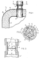
- Figure 1 is a longitudinal section of a portion of a water tank showing a damper device associated with the outlet of the water tank;
- Figure 2 is a section taken along line 3 - 3 of Figure 1; and
- Figure 3 is a sectional view of part of Figure 1 showing the damper in the open condition with water flow.
- Figure 1 illustrates a portion of a conventional storage type water heater l.having a
tank 2 to store heated water. Ajacket 3 is spaced outwardly fromtank 2 and a layer of insulating material 4 is located between thetank 2 andjacket 3. Heated water is withdrawn fromtank 2 through an outlet fitting 5 in the upper end of the tank. Anipple 6 inter-connects the outlet fitting 5 with ahot water pipe 7. - In accordance with the invention, a
damper device 8 is associated withnipple 6 and serves to minimise hot water heat loss during standby periods through the outlet fitting.Damper device 8 includes acylindrical sleeve 9 which is secured to the inner surface ofnipple 6, and a plurality offlaps 10 are integrally connected tosleeve 9 by hinges 11 and, when in the closed position, extend transversely across thenipple 6. While Figure 2 shows threeflaps 10 being utilised, it is contemplated that one or more flaps can be employed. - The
damper device 8, including thesleeve 9,flaps 10 and hinges 11, is preferably formed as a one piece moulded plastic unit. - As shown in Figure 2, each
flap 10 includes a generally curved or arcuateouter edge 12 which complements the inner surface ofsleeve 9, and each flap is also provided with a pair of generally straight side edges 13 which are disposed alongside corresponding side edges of adjacent flaps, when the flaps are in the closed position. - As illustrated in Figure 2, the hinges 11 extend only through a portion of the circumferential dimension of the
outer edges 12.. - Under no flow conditions,
flaps 10 will extend transversely across thenipple 6 to thereby substantially prevent hot water heat loss through fitting 5 by convection. On demand for hot water, the water flow through outlet fitting 5 will pivot theflaps 10 upwardly, as shown by the dashed lines in Figure 3, to thereby open the nipple and provide minimum restriction to flow. When the demand for heated water ceases and flow terminates, theflaps 10 will automatically return to their original transverse position to prevent convection flow through the nipple. - The thickness of the hinges 11, as well as their circumferential dimension and the material of the hinge, is designed so that the hinges will readily be moved to the full open position under normal flow rates encountered in a water heater and will have memory to return to their original closed condition ater water flow has ceased.
- The damper device of the invention is preferably a one piece moulded plastic item which will minimise hot water heat loss during standby periods in the water heater. As such, it is inexpensive to produce and there is no operating noise involved in the movement of the flaps between the open and closed positions.
Claims (6)
1. A hot water tank having a water flow conduit, characterised by a hinged damper (8) in the conduit and biasing means for urging the damper to a closed position wherein the damper is disposed transversely across the conduit to prevent hot water heat loss from the heated water by convection, the hinge (11) being arranged and constructed to permit the damper to move to an open position under conditions of water flow through the conduit.
2. A hot water tank according to claim 1 characterised by a cylindrical sleeve (9) disposed on the inner surface of the conduit, to which the damper (8) is hinged.
3. A hot water tank according to claim 2 characterised in that the conduit includes a fitting (5) connected to the tank and a nipple (6) connected to the fitting (5) within which the sleeve (9) is disposed and the damper is in the form of a flap (10) integrally hinged to the sleeve.
4. A hot water tank according to claim 3, characterised by a plurality of flaps (10), each including an outer arcuate edge (12) complementing the inner surface of the sleeve (9) and each including a pair of side edges (13) disposed alongside corresponding side edges of adjacent flaps when the flaps are in the closed position.
5. A hot water tank according to claim 4, characterised in that each flap is connected to the sleeve along a hinge portion (11) which is smaller in circumferential dimension than the arcuate edge (13).
6. A water tank according to any one of claims 3 to 5, characterised in that the sleeve (9) and the flaps (10) are an integrally moulded plastic unit.
Applications Claiming Priority (2)
| Application Number | Priority Date | Filing Date | Title |
|---|---|---|---|
| US685538 | 1984-12-24 | ||
| US06/685,538 US4579104A (en) | 1984-12-24 | 1984-12-24 | Device for minimizing hot water heat loss in a water heater |
Publications (2)
| Publication Number | Publication Date |
|---|---|
| EP0186515A2 true EP0186515A2 (en) | 1986-07-02 |
| EP0186515A3 EP0186515A3 (en) | 1986-08-13 |
Family
ID=24752632
Family Applications (1)
| Application Number | Title | Priority Date | Filing Date |
|---|---|---|---|
| EP19850309493 Withdrawn EP0186515A3 (en) | 1984-12-24 | 1985-12-24 | Hot water tank with reduced heat loss |
Country Status (3)
| Country | Link |
|---|---|
| US (1) | US4579104A (en) |
| EP (1) | EP0186515A3 (en) |
| CA (1) | CA1262430A (en) |
Cited By (5)
| Publication number | Priority date | Publication date | Assignee | Title |
|---|---|---|---|---|
| EP0393010A2 (en) * | 1989-03-13 | 1990-10-17 | Austria Email-EHT Aktiengesellschaft | Device for the temperature controlled flow of fluids and for preventing the thermally-caused circulation flow in standing, temperature layered fluid columns |
| EP0580946A1 (en) * | 1992-07-28 | 1994-02-02 | Längerer & Reich GmbH & Co. | Heat storage device, especially latent heat storage device |
| AT397300B (en) * | 1989-06-19 | 1994-03-25 | Eggert Heinz | Low-temperature wall heating |
| DE4336190A1 (en) * | 1993-02-19 | 1994-08-25 | Andreas Sebald | Heat restrictor for a storage water heater |
| GB2323658A (en) * | 1997-03-26 | 1998-09-30 | Kevin Coppard | Liquid heater with mixing device |
Families Citing this family (6)
| Publication number | Priority date | Publication date | Assignee | Title |
|---|---|---|---|---|
| US5277171A (en) * | 1993-02-02 | 1994-01-11 | Bradford-White Corporation | Water heater heat trap |
| US5660802A (en) * | 1994-06-07 | 1997-08-26 | Fountainhead Technologies, Inc. | Water purifier |
| US6269780B1 (en) | 2000-01-28 | 2001-08-07 | Aos Holding Company | Water heater heat trap |
| US6745723B1 (en) * | 2003-07-02 | 2004-06-08 | Rheem Manufacturing Company | Water heater heat trap apparatus |
| US20050263190A1 (en) * | 2004-05-28 | 2005-12-01 | Apcom, Inc. | Double heat trap in unitary body |
| US7270087B2 (en) * | 2004-09-14 | 2007-09-18 | Bradford White Corporation | Heat trap |
Citations (4)
| Publication number | Priority date | Publication date | Assignee | Title |
|---|---|---|---|---|
| FR1124819A (en) * | 1954-05-19 | 1956-10-18 | Thomson Houston Comp Francaise | Improvements to water heaters |
| DE1106622B (en) * | 1959-10-09 | 1961-05-10 | Rau Swf Autozubehoer | Non-return valve for nozzle carriers and pipelines of windshield washer systems |
| GB1354691A (en) * | 1970-02-12 | 1974-05-30 | Black M M | Fluid-operated valves |
| NL7905697A (en) * | 1978-08-04 | 1980-02-06 | Smith Corp A O | Heat economiser for a water heater - has ball valves closing inlet and outlet in absence of flow |
Family Cites Families (5)
| Publication number | Priority date | Publication date | Assignee | Title |
|---|---|---|---|---|
| US1991557A (en) * | 1933-02-06 | 1935-02-19 | Johnson Oscar | Water heater |
| US3200571A (en) * | 1961-08-30 | 1965-08-17 | Shannah Gale Stone | Disposable filter bag |
| US3701560A (en) * | 1970-12-30 | 1972-10-31 | Arthur F Emmerson | Automotive vehicle body access and drain plug |
| US3750710A (en) * | 1971-10-12 | 1973-08-07 | Sanders Associates Inc | Variable fluid orifice |
| US4286573A (en) * | 1978-08-04 | 1981-09-01 | A. O. Smith Corporation | Water heater heat trap assembly |
-
1984
- 1984-12-24 US US06/685,538 patent/US4579104A/en not_active Expired - Fee Related
-
1985
- 1985-12-20 CA CA000498299A patent/CA1262430A/en not_active Expired
- 1985-12-24 EP EP19850309493 patent/EP0186515A3/en not_active Withdrawn
Patent Citations (4)
| Publication number | Priority date | Publication date | Assignee | Title |
|---|---|---|---|---|
| FR1124819A (en) * | 1954-05-19 | 1956-10-18 | Thomson Houston Comp Francaise | Improvements to water heaters |
| DE1106622B (en) * | 1959-10-09 | 1961-05-10 | Rau Swf Autozubehoer | Non-return valve for nozzle carriers and pipelines of windshield washer systems |
| GB1354691A (en) * | 1970-02-12 | 1974-05-30 | Black M M | Fluid-operated valves |
| NL7905697A (en) * | 1978-08-04 | 1980-02-06 | Smith Corp A O | Heat economiser for a water heater - has ball valves closing inlet and outlet in absence of flow |
Cited By (7)
| Publication number | Priority date | Publication date | Assignee | Title |
|---|---|---|---|---|
| EP0393010A2 (en) * | 1989-03-13 | 1990-10-17 | Austria Email-EHT Aktiengesellschaft | Device for the temperature controlled flow of fluids and for preventing the thermally-caused circulation flow in standing, temperature layered fluid columns |
| EP0393010A3 (en) * | 1989-03-13 | 1991-05-22 | Austria Email-EHT Aktiengesellschaft | Device for the temperature controlled flow of fluids and for preventing the thermally-caused circulation flow in standing, temperature layered fluid columns |
| AT397300B (en) * | 1989-06-19 | 1994-03-25 | Eggert Heinz | Low-temperature wall heating |
| EP0580946A1 (en) * | 1992-07-28 | 1994-02-02 | Längerer & Reich GmbH & Co. | Heat storage device, especially latent heat storage device |
| US5449035A (en) * | 1992-07-28 | 1995-09-12 | Langerer & Reich Gmbh & Co. | Heat accumulator, in particular latent heat accumulator |
| DE4336190A1 (en) * | 1993-02-19 | 1994-08-25 | Andreas Sebald | Heat restrictor for a storage water heater |
| GB2323658A (en) * | 1997-03-26 | 1998-09-30 | Kevin Coppard | Liquid heater with mixing device |
Also Published As
| Publication number | Publication date |
|---|---|
| CA1262430A (en) | 1989-10-24 |
| EP0186515A3 (en) | 1986-08-13 |
| US4579104A (en) | 1986-04-01 |
Similar Documents
| Publication | Publication Date | Title |
|---|---|---|
| EP0186515A2 (en) | Hot water tank with reduced heat loss | |
| US5183029A (en) | Hot water supply system | |
| US4207866A (en) | Solar heating system including freeze protection | |
| US4403602A (en) | Control valve unit for solar energy system | |
| US5838879A (en) | Continuously cleaned pressureless water heater with immersed copper fluid coil | |
| ES2064192A2 (en) | Water piping system. | |
| EP0616174B1 (en) | A device for storing solar energy | |
| CA2349607C (en) | Flow limiter | |
| US6173118B1 (en) | Sensor block and automatic fill valve for water with immersed copper fluid coil | |
| US4336792A (en) | Solar heating freeze protection system | |
| US5975421A (en) | Hot-water heating apparatus | |
| US2481720A (en) | Heat conservation means for domestic hot-water systems | |
| US2878804A (en) | Apparatus for heating liquids | |
| JPH024136A (en) | Heating device | |
| JPS6011056A (en) | Hot-water supplying device | |
| CN207019291U (en) | Water-heater water tank water inlet insulation construction and water heater | |
| US4759497A (en) | System for heating and storing a liquid | |
| JPH083880Y2 (en) | Electric water heater | |
| KR900013264A (en) | Electric water heater | |
| US2220079A (en) | Air cushion fitting for thermal systems | |
| US2733050A (en) | Reservoir for congealable liquids | |
| JPH0218430Y2 (en) | ||
| EP1267130A1 (en) | Accumulator | |
| US6349677B1 (en) | Steam boiler piping | |
| DE69507540T2 (en) | Device for a water heater |
Legal Events
| Date | Code | Title | Description |
|---|---|---|---|
| PUAI | Public reference made under article 153(3) epc to a published international application that has entered the european phase |
Free format text: ORIGINAL CODE: 0009012 |
|
| PUAL | Search report despatched |
Free format text: ORIGINAL CODE: 0009013 |
|
| AK | Designated contracting states |
Kind code of ref document: A2 Designated state(s): AT BE CH DE FR GB IT LI NL SE |
|
| AK | Designated contracting states |
Kind code of ref document: A3 Designated state(s): AT BE CH DE FR GB IT LI NL SE |
|
| STAA | Information on the status of an ep patent application or granted ep patent |
Free format text: STATUS: THE APPLICATION IS DEEMED TO BE WITHDRAWN |
|
| 18D | Application deemed to be withdrawn |
Effective date: 19870216 |
|
| RIN1 | Information on inventor provided before grant (corrected) |
Inventor name: SNAVELY, ROBERT L. |