EP0186332A1 - Compresseur centrifuge à contrôle de capacité auto-optimisant - Google Patents
Compresseur centrifuge à contrôle de capacité auto-optimisant Download PDFInfo
- Publication number
- EP0186332A1 EP0186332A1 EP85308683A EP85308683A EP0186332A1 EP 0186332 A1 EP0186332 A1 EP 0186332A1 EP 85308683 A EP85308683 A EP 85308683A EP 85308683 A EP85308683 A EP 85308683A EP 0186332 A1 EP0186332 A1 EP 0186332A1
- Authority
- EP
- European Patent Office
- Prior art keywords
- compressor
- speed
- signal
- guide vanes
- inlet guide
- Prior art date
- Legal status (The legal status is an assumption and is not a legal conclusion. Google has not performed a legal analysis and makes no representation as to the accuracy of the status listed.)
- Granted
Links
Images


Classifications
-
- F—MECHANICAL ENGINEERING; LIGHTING; HEATING; WEAPONS; BLASTING
- F25—REFRIGERATION OR COOLING; COMBINED HEATING AND REFRIGERATION SYSTEMS; HEAT PUMP SYSTEMS; MANUFACTURE OR STORAGE OF ICE; LIQUEFACTION SOLIDIFICATION OF GASES
- F25B—REFRIGERATION MACHINES, PLANTS OR SYSTEMS; COMBINED HEATING AND REFRIGERATION SYSTEMS; HEAT PUMP SYSTEMS
- F25B49/00—Arrangement or mounting of control or safety devices
- F25B49/02—Arrangement or mounting of control or safety devices for compression type machines, plants or systems
- F25B49/025—Motor control arrangements
-
- F—MECHANICAL ENGINEERING; LIGHTING; HEATING; WEAPONS; BLASTING
- F04—POSITIVE - DISPLACEMENT MACHINES FOR LIQUIDS; PUMPS FOR LIQUIDS OR ELASTIC FLUIDS
- F04D—NON-POSITIVE-DISPLACEMENT PUMPS
- F04D27/00—Control, e.g. regulation, of pumps, pumping installations or pumping systems specially adapted for elastic fluids
- F04D27/02—Surge control
- F04D27/0246—Surge control by varying geometry within the pumps, e.g. by adjusting vanes
-
- F—MECHANICAL ENGINEERING; LIGHTING; HEATING; WEAPONS; BLASTING
- F04—POSITIVE - DISPLACEMENT MACHINES FOR LIQUIDS; PUMPS FOR LIQUIDS OR ELASTIC FLUIDS
- F04D—NON-POSITIVE-DISPLACEMENT PUMPS
- F04D27/00—Control, e.g. regulation, of pumps, pumping installations or pumping systems specially adapted for elastic fluids
- F04D27/02—Surge control
- F04D27/0261—Surge control by varying driving speed
-
- F—MECHANICAL ENGINEERING; LIGHTING; HEATING; WEAPONS; BLASTING
- F04—POSITIVE - DISPLACEMENT MACHINES FOR LIQUIDS; PUMPS FOR LIQUIDS OR ELASTIC FLUIDS
- F04D—NON-POSITIVE-DISPLACEMENT PUMPS
- F04D27/00—Control, e.g. regulation, of pumps, pumping installations or pumping systems specially adapted for elastic fluids
- F04D27/02—Surge control
- F04D27/0284—Conjoint control of two or more different functions
-
- F—MECHANICAL ENGINEERING; LIGHTING; HEATING; WEAPONS; BLASTING
- F25—REFRIGERATION OR COOLING; COMBINED HEATING AND REFRIGERATION SYSTEMS; HEAT PUMP SYSTEMS; MANUFACTURE OR STORAGE OF ICE; LIQUEFACTION SOLIDIFICATION OF GASES
- F25B—REFRIGERATION MACHINES, PLANTS OR SYSTEMS; COMBINED HEATING AND REFRIGERATION SYSTEMS; HEAT PUMP SYSTEMS
- F25B49/00—Arrangement or mounting of control or safety devices
- F25B49/02—Arrangement or mounting of control or safety devices for compression type machines, plants or systems
- F25B49/022—Compressor control arrangements
-
- F—MECHANICAL ENGINEERING; LIGHTING; HEATING; WEAPONS; BLASTING
- F25—REFRIGERATION OR COOLING; COMBINED HEATING AND REFRIGERATION SYSTEMS; HEAT PUMP SYSTEMS; MANUFACTURE OR STORAGE OF ICE; LIQUEFACTION SOLIDIFICATION OF GASES
- F25B—REFRIGERATION MACHINES, PLANTS OR SYSTEMS; COMBINED HEATING AND REFRIGERATION SYSTEMS; HEAT PUMP SYSTEMS
- F25B2600/00—Control issues
- F25B2600/02—Compressor control
- F25B2600/021—Inverters therefor
-
- Y—GENERAL TAGGING OF NEW TECHNOLOGICAL DEVELOPMENTS; GENERAL TAGGING OF CROSS-SECTIONAL TECHNOLOGIES SPANNING OVER SEVERAL SECTIONS OF THE IPC; TECHNICAL SUBJECTS COVERED BY FORMER USPC CROSS-REFERENCE ART COLLECTIONS [XRACs] AND DIGESTS
- Y02—TECHNOLOGIES OR APPLICATIONS FOR MITIGATION OR ADAPTATION AGAINST CLIMATE CHANGE
- Y02B—CLIMATE CHANGE MITIGATION TECHNOLOGIES RELATED TO BUILDINGS, e.g. HOUSING, HOUSE APPLIANCES OR RELATED END-USER APPLICATIONS
- Y02B30/00—Energy efficient heating, ventilation or air conditioning [HVAC]
- Y02B30/70—Efficient control or regulation technologies, e.g. for control of refrigerant flow, motor or heating
Definitions
- This invention relates generally to refrigeration systems and more particularly, it relates to a self-optimizing, capacity control system for inverter-driven centrifugal compressor based water chillers wherein adjustable inlet guide vanes and compressor speed are both automatically regulated in response to a continually updated "learned" chiller surge surface so as to realize minimum overall chiller energy consumption.
- This invention provides a self-optimizing, capacity control system for inverter-driven centrifugal compressor based water chillers wherein adjustable inlet guide vanes and compressor speed are both automatically regulated in response to a continually updated "learned" chiller surge surface so as to realize the minimum overall chiller energy consumption.
- a microprocessor having a random-access memory which periodically identifies the location of the surge surface at the current operating point of the chiller and updates that surge surface information in the random-access memory during a "learning" mode. Then, the microprocessor causes the chiller to operate at a safety margin away from the surge surface during an"operating" mode for minimum energy consumption.
- the present invention uses all of the same input signals to the control system block 50 in the '725 patent except that (1) the condenser temperature from the thermistor 56 is replaced by an absolute condenser pressure signal taken from the transducer 110 on line 111 of '719 patent and (2) the evaporator temperature from the thermistor 58 is replaced by an absolute evaporator pressure signal taken from the transducer 112 on line 113 of the '719 patent. Further, the amplifier 59 of the '725 patent is replaced by a functional generator 104 formed by the blocks 120 and 123 in Figure 2 of the '719 patent. The substantial improvement of the present invention depends in part upon substituting the electronic circuitry of the control system 50 illustrated in Figure 6A, 6B and 6C of the '725 patent by a microprocessor having a random-access memory for storing the updated surge surface information.
- the present invention is concerned with the provision of a self-optimizing, capacity control system for a refrigeration system which includes a compressor, condenser and an evaporator, all connected in a closed refrigeration circuit.
- the compressor has a plurality of adjustable inlet guide vanes, a motor connected to regulate the inlet guide vanes position, and an electrical variable speed motor connected to drive the compressor.
- the self-optimizing, capacity control system includes means for sensing the absolute condenser pressure to generate a first signal and means for sensing the absolute evaporator pressure to generate a second signal.
- Means for sensing the physical position of the inlet guide vanes is provided to generate a fifth signal.
- Means for sensing the temperature of the chilled water discharged from the evaporator is provided to generate a sixth signal.
- a means for sensing a temperature set point is provided.
- a microprocessor responsive to the first through the seventh signals generates control signals to regulate automatically both the speed of the compressor drive motor and the position of the inlet guide vanes so as to realize minimum overall chiller energy consumption.
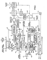
- Figure 1 in block diagram form a refrigeration or cooling system which includes a centrifugal compressor 20 for passing a refrigerant through line 21 to a condenser 22.
- Water from a cooling tower enters on line 23 and leaves on line 24, the water being in heat exchange relationship with the liquid refrigerant in the condenser 22.
- a refrigerant at the discharge side of condenser 22 is delivered to a fixed orifice 26 via line 25.
- the outlet of the orifice 26 is passed over line 27 to the refrigerant inlet connection of an evaporator 28.
- the refrigerant is then passed through the evaporator and out a suction duct 30 laving a plurality of inlet guide vanes 31 or Pre-rotational vanes (PRV).
- PRV Pre-rotational vanes
- the position of the guide lanes 31 is regulated by a small PRV motor 32 which receives a control signal on line 33.
- the higher tem- perature of water from a building or cooling load enters on line 34 and leaves as chilled water on Line 35, the building water being in heat exchange relationship with the refrigerant vapor in the evaporator 28.
- An electrical prime mover such as an induction motor 36 is coupled over a shaft 39 for driving the centrifugal compressor 20.
- the motor 36 is in turn driven from an inverter 37 which receives a DC input voltage over line 38 so as to determine the amplitude of the inverter output voltage.
- a voltage control circuit 40 is provided between a voltage supply line 41 and the line 38 which delivers the DC input voltage to the inverter 37.
- the frequency of the inverter output voltage is resulted by the periodicity of timing or gating signals appearing on line 43 from a logic circuit 44.
- a regulating input signal through the logic circuit on line 45 may be a DC voltage for controlling a voltage-controlled oscillator in the logic circuit to provide output pulses at a frequency determined by the amplitude of the signal on line 45.
- the logic circuit generally includes a ring counter-type circuit to distribute the impulses to the switching means such as thyristors in the inverter 37.
- the components of the present refrigeration system are quite conventional in nature and are the same components as shown in Figure 1 of Patent No. 4,151,725 which is hereby incorporated by reference.
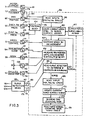
- the substantial improvement of the present invention depends in part upon the provision of a microprocessor 106 with random-access memory (RAM) 107 which is utilized to automatically regulate both the speed of the induction motor 36 via line 51 and the physical position of the pre-rotational vanes 31 via line 33 so as to realize minimum overall chiller energy consumption.
- the vane control signal on line 33 can be either an "open vanes” signal on line 53 or a "closed vanes” signal on line 54, or no signal (“hold vanes").
- the output speed control signal from the microprocessor 106 on line 112 is fed through a digital-to-analog (D/A) converter 114 for supplying the line 51.
- the vane position control signals from the microprocessor 106 on lines 116 and 118 are fed through respective D/A converters 120 and 121 for supplying the respective lines 53 and 54.
- a first input signal on line 55 is provided by a first compressor transducer 56 and is a function of the absolute pressure in the condenser 22.
- a second input signal on line 57 is obtained from a second pressure transducer 58 and is a function of the absolute pressure in the evaporator 28.
- the first input signal is fed through analog-to-digital (A/D) converter 122 for driving the microprocessor 106 via line 124.
- the second input signal is fed through A/D converter 126 for driving the microprocessor 106 via line 128.
- the pressure transducers 56, 58 are the same type as pressure transducers 110 and 112 described in Figure 1 of U. S. Patent No. 4,282,719 which is hereby incorporated by reference.
- a third input signal on line 71 which is representative of the amplitude of the current flowing through the winding of the induction motor 36.
- This motor current signal is fed through A/D converter 179 for driving the microprocessor 106 via line 181.
- This motor current signal may be derived from a current transformer 75 connected to the motor 36 via a line 77.
- the first, second and third input signals representative of the respective condenser pressure, evaporator pressure and . motor current define input signals for surge detector means 165 for the chiller of the present invention as will be explained in more detail later.
- a fourth input signal on line 72 is provided which is representative of the actual motor speed of the induction motor 36.
- This motor speed signal is fed to A/D converter 183 for driving the microprocessor 106 via line 184. It should be understood that the actual motor speed can be derived via a conventional tachometer 73 connected to the motor 36 via a line 74.
- a fifth input signal on line 62 is provided by a potentiometer 61 with its movable arm or wiper mechanically coupled to the output shaft of the PRV motor 32 as indicated by the dotted lines 61a. Therefore, this fifth input signal indicates (i.e., wide open vanes - WOV, 3/4 open, 1/2 open and so forth) of the inlet guide vanes 31 in a continuous manner.
- the fifth signal is fed through A/D converter 130 for driving the microprocessor 106 via line 132.
- a sixth input signal on line 64 is obtained from a thermistor 63 positioned to sense the temperature of the chilled water discharged from the evaporator 28.
- This sixth signal represents the instantaneous load condition and is fed through A/D converter 134 for driving the microprocessor 106 via line 136.
- a seventh input signal on line 138 is obtained from a potentiometer 66 and represents a temperature set point or desired condition signal. This seventh signal is fed through A/D converter 140 to the microprocessor 106 via line 142.
- Figure 2 depicts how lines of constant chiller power appear on a chart where the PRV setting is plotted along the left ordinate and the compressor speed is plotted along the abcissa. For example, if the PRV setting is equal to the PRVi and the compressor speed is equal to Si, there is defined a particular operating point i.
- the microprocessor Prior to initiation of "learning mode", the microprocessor will determine the current operating point in an initial surge surface array for the various input signals. The method for generating the initial surge surface array which is stored in a random-access memory (RAM) 107 of the microprocessor 106 will be explained hereinafter.
- RAM random-access memory
- the microprocessor Upon start-up of the "learning mode", the microprocessor will lower incrementally the compressor speed such as by approximately .1 hz to a point "a". Then, with the speed being held constant the chilled water temperature control is closed by moving of the PRV to a point "b" so that the error in the water temperature is within t.lo p from the water set point temperature. This process is continually repeated along point "c", “d”, “e”, and "f” until a surge is detected at the point "f". The current surge surface array stored in the RAM is now updated with the detected surge conditions or information reltive to the PRV position, compressor speed, and pressure ratio. Finally, the microprocessor will suspend the "learning” mode and activate the normal "operating" mode which now will be described.
- the PR V are held in a fully opened position and the compressor speed is increased or decreased so as to meet the load requirement by maintaining constant the leaving chilled water temperature. If a reduced load requires a lower capacity, the microprocessor will shift to the partly open vane region of control.
- errors in the chilled water temperature are controlled by changing both the PRV position and the compressor speed.
- the primary chiller capacity control is accomplished by adjusting the PRV position. The PRV are moved to a more open position if a chiller capacity is increased and to a more closed position if the chiller capacity is decreased.
- the secondary chiller capacity control is accomplished by adjusting the compressor speed so as to increase or set it at a safety margin, such as .5 hz to a point "g" in Figure 2, away from the surge speed as determined from the latest surge surface during the "learning" mode.
- a safety margin such as .5 hz to a point "g" in Figure 2
- the compressor speed is a function of the PRV position and the head measurement (approximated by the pressure ratio).
- this point "g" defines the minimum energy operating point which is surge free and still satisfies the load and head requirements.
- the microprocessor 106 includes a functional block 104 which receives the first input signal representative of the absolute condenser pressure from line 124 and the second input signal representative of the absolute evaporator pressure from line 128.
- the functional block 104 produces on its output line 105 a signal which is a ratio. This ratio signal is the same as the signal represented on line 124 in Figure 2 of the 1 719 patent.
- a block 158 receives this ratio signal on line 105 which is indicative of the compressor head.
- the input signal representative of the motor speed on the line 184 is also received by the block 158. Further, a fifth input signal representative of the vane position on the line 132 is fed to the block 158.
- a block 160 locates the current operating point such as the point "i" of Figure 2.
- the surge array is stored in the RAM 107. Once the operating point is located, the compressor speed is incrementally decreased in speed by a speed block 162.
- This output speed control signal on the line 112 from the block 162 is utilized to regulate the speed of the induction motor 36 via the D/A converter 114 and the line 51.
- a block 164 receives the sixth input signal representative of the instantaneous load condition from line 136 and the seventh input signal from line 142 representative of the desired condition.
- the block 164 is used to increase or open the position of the vanes so that an error between the chilled water temperature and the temperature set point is within point .1°F.
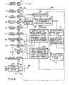
- This surge detection device 165 may be the same the surge detection apparatus 10 of Figure 1 taught in copending application Serial No. 685,686, which was filed on December 24, 1984 in the names of Madeleine M. Lowe and Robert T. Hagerman and assigned to the same assignee as the present invention.
- the surge detection apparatus 10 receives as input signals a motor current signal obtained from a current transformer 24 connected in a phase line 26 of an induction motor 20, a condenser pressure signal obtained from a first pressure transducer 32 connected to the discharge line of the condenser 14, and an evaporator pressure signal obtained from a second pressure transducer 34 connected to the suction side of the compressor.
- the device 165 receives these corresponding input signals on respective lines 181, 124 and 128.
- the apparatus 10 generates as output signals a filtered motor current signal on line 63, a filtered differential pressure signal on line 60, a filtered current threshold signal on line 70 and a filtered differential pressure threshold signal on line 72.
- the device 165 generates these corresponding output signals on lines 167, 169, 171 and 173 which are fed to the microprocessor 106.
- the surge detector block 166 in the microprocessor 106 depicted in Figure 3 of the present invention is formed in the manner as the flow chart shown in Figure 2 of the aforementioned copending application.
- the block 166 will indicate that the compressor is surging when the differential pressure threshold and current threshold signals are exceeded within a pre-selected time interval.
- a block 168 reads the PRV position, condenser pressure, evaporator pressure, and compressor speed. This new information is updated by a block 170 for storing in the RAM 107. Thereafter, blocks 172 and 174 causes discontinuation of the "learning" mode and activates the normal "operating" mode of the system, respectively.
- a block 176 increases the compressor speed until the system is no longer in the surge condition. Once it is determined that the compressor is not surging any block 166, a block 178 will open the position of the vanes if the chilled water temperature is determined to be too hot by the "open vanes' control signal on line 116. On the other hand, if the chilled water temperature is too cold, the block 178 will cause the position of the vanes to close by the "closed vanes" control signal on line 118. These same control signals are used to regulate the PRV motor 32 via the line 33.
- the compressor speed is increased a safety margin such as .5 hz from the current surge speed surface stored in the . RAM 107. This is accomplished by the output speed control signal on the line 112 from the block 180 which is utilized to regulate the speed of the induction motor via the DA converter 114 via the line 51.
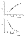
- the initial surge surface speed array can be generated and shown in Table II of the Appendix.
- Table II the columns are designated by the pressure ration P cd/ P ev whle the rows are designated by PRV position with 2.00 volts corresponding to the closed vane position and 10.00 volts corresponding to the wide open vane position.
- the tabulated surge surface speed are scaled such that 9.99 volts corresponds to 60 hz inverter frequency. Further, this information can be plotted to provide a typical initial surge surface which is illustrated in Figure 7 of the drawings. This initial surge surface is the one stored initially in the RAM 107 of the microprocessor.
- an adjusted surge surface is shown as a dot-dash line in Figure 7 whch illustrates a surge speed that is above the previously "learned" surface.
- the present invention provides a self-optimizing, inverter-driven centrifugal compressor based water chiller control system wherein adjustable inlet guide vanes and compressor speed are both automatically regulated in response to a continually updated "learned" chiller surge surface so as to realize minimum overall chiller energy consumption.
- the control system of the present invention includes a microprocessor having a random-access memory for storing an updated current surge surface during the "learning" mode. Further, during the "operating" mode the compressor speed is set at a safety margin away from the current surge speed surface.
Landscapes
- Engineering & Computer Science (AREA)
- Mechanical Engineering (AREA)
- General Engineering & Computer Science (AREA)
- Physics & Mathematics (AREA)
- Thermal Sciences (AREA)
- Geometry (AREA)
- Control Of Positive-Displacement Air Blowers (AREA)
- Devices That Are Associated With Refrigeration Equipment (AREA)
Applications Claiming Priority (2)
| Application Number | Priority Date | Filing Date | Title |
|---|---|---|---|
| US685685 | 1984-12-24 | ||
| US06/685,685 US4608833A (en) | 1984-12-24 | 1984-12-24 | Self-optimizing, capacity control system for inverter-driven centrifugal compressor based water chillers |
Publications (2)
| Publication Number | Publication Date |
|---|---|
| EP0186332A1 true EP0186332A1 (fr) | 1986-07-02 |
| EP0186332B1 EP0186332B1 (fr) | 1989-03-01 |
Family
ID=24753274
Family Applications (1)
| Application Number | Title | Priority Date | Filing Date |
|---|---|---|---|
| EP85308683A Expired EP0186332B1 (fr) | 1984-12-24 | 1985-11-28 | Compresseur centrifuge à contrôle de capacité auto-optimisant |
Country Status (5)
| Country | Link |
|---|---|
| US (1) | US4608833A (fr) |
| EP (1) | EP0186332B1 (fr) |
| JP (1) | JPH0742958B2 (fr) |
| CA (1) | CA1238395A (fr) |
| DE (1) | DE3568470D1 (fr) |
Cited By (14)
| Publication number | Priority date | Publication date | Assignee | Title |
|---|---|---|---|---|
| EP0686774A1 (fr) * | 1994-05-23 | 1995-12-13 | Ebara Corporation | Turbomachine avec dispositifs de guidage à pas variable |
| WO1997050022A1 (fr) * | 1996-06-27 | 1997-12-31 | York International Corporation | Controle de vitesse variable a logique floue pour refroidisseur centrifuge |
| GB2316772A (en) * | 1993-08-16 | 1998-03-04 | American Standard Inc | Control system method for a centrifugal compressor |
| US6772599B2 (en) | 2002-08-06 | 2004-08-10 | York International Corporation | Stability control system and method for compressors operating in parallel |
| US7328587B2 (en) | 2004-01-23 | 2008-02-12 | York International Corporation | Integrated adaptive capacity control for a steam turbine powered chiller unit |
| US7421853B2 (en) | 2004-01-23 | 2008-09-09 | York International Corporation | Enhanced manual start/stop sequencing controls for a stream turbine powered chiller unit |
| US7421854B2 (en) | 2004-01-23 | 2008-09-09 | York International Corporation | Automatic start/stop sequencing controls for a steam turbine powered chiller unit |
| WO2011092157A1 (fr) * | 2010-01-27 | 2011-08-04 | Siemens Aktiengesellschaft | Procédé et système de commande de compresseur |
| WO2014058524A1 (fr) * | 2012-10-09 | 2014-04-17 | Carrier Corporation | Commande d'aube directrice d'entrée de compresseur centrifuge |
| US20140260385A1 (en) * | 2013-03-15 | 2014-09-18 | Daikin Industries, Ltd. | Refrigerating apparatus and control device for refrigerating machine |
| EP2426433A3 (fr) * | 2010-09-01 | 2015-04-08 | Mitsubishi Heavy Industries, Ltd. | Dispositif d'évaluation de la performance pour dispositif frigorifique centrifuge |
| EP2322877A3 (fr) * | 2009-10-20 | 2015-05-27 | Johnson Controls Technology Company | Contrôleurs et procédés permettant de fournir une génération informatique et utilisation d'une carte de surtension tridimensionnelle pour le contrôle des refroidisseurs |
| CN105074360A (zh) * | 2012-12-04 | 2015-11-18 | 特灵国际有限公司 | 冷却器容量控制设备、方法和系统 |
| EP2465196A4 (fr) * | 2009-08-10 | 2017-03-29 | Emerson Climate Technologies, Inc. | Module de commande et procédé pour minimiser le courant d'avance de phase |
Families Citing this family (44)
| Publication number | Priority date | Publication date | Assignee | Title |
|---|---|---|---|---|
| US4715190A (en) * | 1985-11-21 | 1987-12-29 | American Standard Inc. | Control and method for modulating the capacity of a temperature conditioning system |
| US4686834A (en) * | 1986-06-09 | 1987-08-18 | American Standard Inc. | Centrifugal compressor controller for minimizing power consumption while avoiding surge |
| US4734628A (en) * | 1986-12-01 | 1988-03-29 | Carrier Corporation | Electrically commutated, variable speed compressor control system |
| US4856286A (en) * | 1987-12-02 | 1989-08-15 | American Standard Inc. | Refrigeration compressor driven by a DC motor |
| US4829779A (en) * | 1987-12-15 | 1989-05-16 | Hussmann Corporation | Interface adapter for interfacing a remote controller with commercial refrigeration and environmental control systems |
| EP0347821B1 (fr) * | 1988-06-21 | 1995-08-30 | Daikin Industries, Limited | Appareil de commande de température pour système de refroidissement par liquide |
| JPH0739451B2 (ja) * | 1988-08-30 | 1995-05-01 | 宇部興産株式会社 | 末端変性イミドオリゴマー組成物 |
| EP0541157A1 (fr) * | 1991-11-04 | 1993-05-12 | Whirlpool Europe B.V. | Dispositif de réfrigération |
| US5203179A (en) * | 1992-03-04 | 1993-04-20 | Ecoair Corporation | Control system for an air conditioning/refrigeration system |
| US5355691A (en) * | 1993-08-16 | 1994-10-18 | American Standard Inc. | Control method and apparatus for a centrifugal chiller using a variable speed impeller motor drive |
| US5537830A (en) * | 1994-11-28 | 1996-07-23 | American Standard Inc. | Control method and appartus for a centrifugal chiller using a variable speed impeller motor drive |
| CA2184882A1 (fr) * | 1995-09-08 | 1997-03-09 | Hideomi Harada | Turbomachine avec aubes directrices a angle variable |
| US5746062A (en) * | 1996-04-11 | 1998-05-05 | York International Corporation | Methods and apparatuses for detecting surge in centrifugal compressors |
| KR20000015873A (ko) * | 1996-05-22 | 2000-03-15 | 로날드 지. 헬러 | 원심 압축기에서의 서지 발생 검출방법 |
| US5873257A (en) * | 1996-08-01 | 1999-02-23 | Smart Power Systems, Inc. | System and method of preventing a surge condition in a vane-type compressor |
| ATE285037T1 (de) | 1998-03-19 | 2005-01-15 | Nsb Gas Proc Ag | Verfahren und sensor zur detektion von kavitationen, sowie vorrichtung enthaltend einen solchen sensor |
| US6202431B1 (en) | 1999-01-15 | 2001-03-20 | York International Corporation | Adaptive hot gas bypass control for centrifugal chillers |
| IT1314887B1 (it) * | 2000-12-13 | 2003-01-16 | Magnetek Spa | Metodo per la riduzione dei consumi energetici in una macchinafrigorifera, e macchina frigorifera operante secondo detto metodo |
| US7905102B2 (en) * | 2003-10-10 | 2011-03-15 | Johnson Controls Technology Company | Control system |
| US20050241323A1 (en) * | 2004-04-07 | 2005-11-03 | Miller Wanda J | Energy analyzer for a refrigeration system |
| US8307645B2 (en) * | 2005-11-02 | 2012-11-13 | General Electric Company | Apparatus and method for avoidance of turbocharger surge on locomotive diesel engines |
| US7854596B2 (en) * | 2007-01-24 | 2010-12-21 | Johnson Controls Technology Company | System and method of operation of multiple screw compressors with continuously variable speed to provide noise cancellation |
| US20090024295A1 (en) * | 2007-07-17 | 2009-01-22 | Kendall Roger Swenson | System and method for remotely monitoring a turbocharged engine |
| CN101755179B (zh) * | 2007-07-17 | 2012-02-15 | 江森自控科技公司 | 控制系统 |
| GB0716329D0 (en) * | 2007-08-21 | 2007-10-03 | Compair Uk Ltd | Improvements in compressors control |
| DE102008058799B4 (de) * | 2008-11-24 | 2012-04-26 | Siemens Aktiengesellschaft | Verfahren zum Betrieb eines mehrstufigen Verdichters |
| KR101761931B1 (ko) | 2009-03-30 | 2017-08-04 | 티마익 코포레이션 | 컴프레서 서지 제어 시스템 및 방법 |
| EP2751430B1 (fr) | 2011-06-23 | 2020-04-22 | Johnson Controls Technology Company | Système et procédé de régulation de capacité pour compresseur centrifuge |
| US10544791B2 (en) | 2011-12-01 | 2020-01-28 | Carrier Corporation | Centrifugal compressor startup control |
| ITCO20110069A1 (it) * | 2011-12-20 | 2013-06-21 | Nuovo Pignone Spa | Disposizione di prova per uno stadio di un compressore centrifugo |
| US9182154B2 (en) * | 2012-01-20 | 2015-11-10 | Mitsubishi Electric Research Laboratories, Inc. | Adaptive control of vapor compression system |
| KR101630178B1 (ko) * | 2012-04-30 | 2016-06-14 | 존슨 컨트롤스 테크놀러지 컴퍼니 | 제어장치 |
| CN104854351B (zh) | 2012-11-09 | 2017-09-01 | 江森自控科技公司 | 具有延伸行程的可变几何形状扩散器及其控制方法 |
| DE112014000566B4 (de) * | 2013-01-25 | 2022-07-28 | Trane International Inc. | Verfahren und Systeme zum Erkennen und Erholen von Steuerinstabilität, die durch Laufradstillstand bewirkt ist |
| CN105102910B (zh) * | 2013-01-25 | 2018-08-21 | 特灵国际有限公司 | 用于控制具有带有可变速度驱动器的离心式压缩机的冷却器系统的方法和系统 |
| WO2016077559A1 (fr) | 2014-11-14 | 2016-05-19 | Carrier Corporation | Calcul de capacité de refroidisseur embarqué |
| JP6543405B2 (ja) | 2015-07-06 | 2019-07-10 | ジョンソン コントロールズ テクノロジー カンパニーJohnson Controls Technology Company | 多段遠心圧縮機のための容量制御システム及び方法 |
| BE1023392B1 (nl) * | 2015-08-31 | 2017-03-01 | Atlas Copco Airpower Naamloze Vennootschap | Werkwijze voor het regelen van het toerental van een compressor in functie van het beschikbaar gasdebiet van een bron en sturing en compressor daarbij toegepast. |
| CN105653812B (zh) * | 2016-01-11 | 2018-12-14 | 东方电气集团东方电机有限公司 | 导叶动态关闭曲线优化方法 |
| CN110821871A (zh) * | 2018-08-13 | 2020-02-21 | 开利公司 | 用于预测离心式制冷压缩机的喘振的系统和其方法以及空调机组 |
| US11732942B2 (en) * | 2020-02-28 | 2023-08-22 | Johnson Controls Tyco IP Holdings LLP | Building system with automatic chiller anti-surge control |
| US11428233B2 (en) | 2020-12-21 | 2022-08-30 | Emerson Climate Technologies, Inc. | Surge control systems and methods for dynamic compressors |
| WO2022140079A2 (fr) * | 2020-12-21 | 2022-06-30 | Emerson Climate Technologies, Inc. | Systèmes et procédés de régulation de surtension pour compresseurs dynamiques |
| CN114992151B (zh) * | 2022-05-30 | 2023-10-13 | 贝德凯利电气(苏州)有限公司 | 风机任意位置随机方法 |
Citations (3)
| Publication number | Priority date | Publication date | Assignee | Title |
|---|---|---|---|---|
| US4151725A (en) * | 1977-05-09 | 1979-05-01 | Borg-Warner Corporation | Control system for regulating large capacity rotating machinery |
| US4282719A (en) * | 1979-09-12 | 1981-08-11 | Borg-Warner Corporation | Control system for regulating large capacity rotating machinery |
| US4546618A (en) * | 1984-09-20 | 1985-10-15 | Borg-Warner Corporation | Capacity control systems for inverter-driven centrifugal compressor based water chillers |
Family Cites Families (4)
| Publication number | Priority date | Publication date | Assignee | Title |
|---|---|---|---|---|
| GB1593361A (en) * | 1977-05-09 | 1981-07-15 | Borg Warner | Control system for regulating large capacity rotating machinery |
| US4142838A (en) * | 1977-12-01 | 1979-03-06 | Compressor Controls Corporation | Method and apparatus for preventing surge in a dynamic compressor |
| US4249238A (en) * | 1978-05-24 | 1981-02-03 | The United States Of America As Represented By The Administrator Of The National Aeronautics And Space Administration | Apparatus for sensor failure detection and correction in a gas turbine engine control system |
| US4490791A (en) * | 1982-04-19 | 1984-12-25 | Chandler Evans Inc. | Adaptive gas turbine acceleration control |
-
1984
- 1984-12-24 US US06/685,685 patent/US4608833A/en not_active Expired - Lifetime
-
1985
- 1985-11-21 CA CA000495877A patent/CA1238395A/fr not_active Expired
- 1985-11-28 EP EP85308683A patent/EP0186332B1/fr not_active Expired
- 1985-11-28 DE DE8585308683T patent/DE3568470D1/de not_active Expired
- 1985-12-24 JP JP60291789A patent/JPH0742958B2/ja not_active Expired - Fee Related
Patent Citations (3)
| Publication number | Priority date | Publication date | Assignee | Title |
|---|---|---|---|---|
| US4151725A (en) * | 1977-05-09 | 1979-05-01 | Borg-Warner Corporation | Control system for regulating large capacity rotating machinery |
| US4282719A (en) * | 1979-09-12 | 1981-08-11 | Borg-Warner Corporation | Control system for regulating large capacity rotating machinery |
| US4546618A (en) * | 1984-09-20 | 1985-10-15 | Borg-Warner Corporation | Capacity control systems for inverter-driven centrifugal compressor based water chillers |
Cited By (32)
| Publication number | Priority date | Publication date | Assignee | Title |
|---|---|---|---|---|
| GB2316714A (en) * | 1993-08-16 | 1998-03-04 | American Standard Inc | A method of operating a centrifugal compressor |
| GB2316714B (en) * | 1993-08-16 | 1998-04-22 | American Standard Inc | Control of variable capacity centrifugal compressors |
| GB2316772B (en) * | 1993-08-16 | 1998-04-22 | American Standard Inc | Control of variable capacity centrifugal compressors |
| GB2316772A (en) * | 1993-08-16 | 1998-03-04 | American Standard Inc | Control system method for a centrifugal compressor |
| EP0886069A3 (fr) * | 1994-05-23 | 1999-03-24 | Ebara Corporation | Turbomachine avec dispositifs de guidage à pas variable |
| US5618160A (en) * | 1994-05-23 | 1997-04-08 | Ebara Corporation | Turbomachinery with variable angle fluid guiding devices |
| EP0886069A2 (fr) * | 1994-05-23 | 1998-12-23 | Ebara Corporation | Turbomachine avec dispositifs de guidage à pas variable |
| KR100381464B1 (ko) * | 1994-05-23 | 2003-07-04 | 가부시키 가이샤 에바라 세이사꾸쇼 | 가변각흐름안내장치를구비한터보기계 |
| EP0686774A1 (fr) * | 1994-05-23 | 1995-12-13 | Ebara Corporation | Turbomachine avec dispositifs de guidage à pas variable |
| WO1997050022A1 (fr) * | 1996-06-27 | 1997-12-31 | York International Corporation | Controle de vitesse variable a logique floue pour refroidisseur centrifuge |
| AU712391B2 (en) * | 1996-06-27 | 1999-11-04 | York International Corporation | Variable speed control of a centrifugal chiller using fuzzy logic |
| US6772599B2 (en) | 2002-08-06 | 2004-08-10 | York International Corporation | Stability control system and method for compressors operating in parallel |
| US7328587B2 (en) | 2004-01-23 | 2008-02-12 | York International Corporation | Integrated adaptive capacity control for a steam turbine powered chiller unit |
| US7421853B2 (en) | 2004-01-23 | 2008-09-09 | York International Corporation | Enhanced manual start/stop sequencing controls for a stream turbine powered chiller unit |
| US7421854B2 (en) | 2004-01-23 | 2008-09-09 | York International Corporation | Automatic start/stop sequencing controls for a steam turbine powered chiller unit |
| EP2465196A4 (fr) * | 2009-08-10 | 2017-03-29 | Emerson Climate Technologies, Inc. | Module de commande et procédé pour minimiser le courant d'avance de phase |
| EP2322877A3 (fr) * | 2009-10-20 | 2015-05-27 | Johnson Controls Technology Company | Contrôleurs et procédés permettant de fournir une génération informatique et utilisation d'une carte de surtension tridimensionnelle pour le contrôle des refroidisseurs |
| EP2354559A1 (fr) * | 2010-01-27 | 2011-08-10 | Siemens Aktiengesellschaft | Système et procédé de contrôle d'un compresseur |
| CN102741554A (zh) * | 2010-01-27 | 2012-10-17 | 西门子公司 | 压缩机控制方法和系统 |
| WO2011092157A1 (fr) * | 2010-01-27 | 2011-08-04 | Siemens Aktiengesellschaft | Procédé et système de commande de compresseur |
| CN102741554B (zh) * | 2010-01-27 | 2014-12-31 | 西门子公司 | 压缩机控制方法和系统 |
| US9574572B2 (en) | 2010-01-27 | 2017-02-21 | Siemens Aktiengesellschaft | Compressor control method and system |
| EP2426433A3 (fr) * | 2010-09-01 | 2015-04-08 | Mitsubishi Heavy Industries, Ltd. | Dispositif d'évaluation de la performance pour dispositif frigorifique centrifuge |
| CN104736952A (zh) * | 2012-10-09 | 2015-06-24 | 开利公司 | 离心式压缩机入口导向叶片控制 |
| CN104736952B (zh) * | 2012-10-09 | 2016-09-14 | 开利公司 | 离心式压缩机入口导向叶片控制 |
| WO2014058524A1 (fr) * | 2012-10-09 | 2014-04-17 | Carrier Corporation | Commande d'aube directrice d'entrée de compresseur centrifuge |
| US9677566B2 (en) | 2012-10-09 | 2017-06-13 | Carrier Corporation | Centrifugal compressor inlet guide vane control |
| CN105074360A (zh) * | 2012-12-04 | 2015-11-18 | 特灵国际有限公司 | 冷却器容量控制设备、方法和系统 |
| CN105074360B (zh) * | 2012-12-04 | 2017-12-26 | 特灵国际有限公司 | 冷却器容量控制设备、方法和系统 |
| US10612827B2 (en) | 2012-12-04 | 2020-04-07 | Trane International Inc. | Chiller capacity control apparatuses, methods, and systems |
| US20140260385A1 (en) * | 2013-03-15 | 2014-09-18 | Daikin Industries, Ltd. | Refrigerating apparatus and control device for refrigerating machine |
| US9797640B2 (en) * | 2013-03-15 | 2017-10-24 | Daikin Applied Americas Inc. | Refrigerating apparatus and corresponding control device |
Also Published As
| Publication number | Publication date |
|---|---|
| JPS61160597A (ja) | 1986-07-21 |
| DE3568470D1 (en) | 1989-04-06 |
| US4608833A (en) | 1986-09-02 |
| CA1238395A (fr) | 1988-06-21 |
| JPH0742958B2 (ja) | 1995-05-15 |
| EP0186332B1 (fr) | 1989-03-01 |
Similar Documents
| Publication | Publication Date | Title |
|---|---|---|
| EP0186332A1 (fr) | Compresseur centrifuge à contrôle de capacité auto-optimisant | |
| EP0175476B1 (fr) | Systèmes de contrôle de capacité pour compresseur centrifuge entraîné par inverseur combiné avec des refroidisseurs d'eau | |
| US4686834A (en) | Centrifugal compressor controller for minimizing power consumption while avoiding surge | |
| US4151725A (en) | Control system for regulating large capacity rotating machinery | |
| EP1496264B1 (fr) | Procédés et appareils pour détecter les phénomènes de pompage dans des compresseurs centrifuges | |
| US4282718A (en) | Evaporator inlet water temperature control system | |
| US5323619A (en) | Control method for starting an air conditioner compressor | |
| US5355691A (en) | Control method and apparatus for a centrifugal chiller using a variable speed impeller motor drive | |
| US5537830A (en) | Control method and appartus for a centrifugal chiller using a variable speed impeller motor drive | |
| US4495779A (en) | Air conditioner | |
| EP1151230B1 (fr) | Regulateur adaptatif de derivation des gaz chauds pour refroidisseurs centrifuges | |
| JP2723339B2 (ja) | ヒートポンプ暖房装置 | |
| US4538422A (en) | Method and control system for limiting compressor capacity in a refrigeration system upon a recycle start | |
| CA1264364A (fr) | Automatisme pour prevenir les surpressions transitoires pour systeme compresseur centrifuge double | |
| JPS6251793A (ja) | 遠心圧縮機の制御方法及び制御装置 | |
| JPS6336436B2 (fr) | ||
| CA1139400A (fr) | Systeme reglable de controle de pompage et de capacite d'un compresseur | |
| US4355948A (en) | Adjustable surge and capacity control system | |
| JPS5956648A (ja) | 空気調和装置 | |
| GB2316714A (en) | A method of operating a centrifugal compressor | |
| JPS5484345A (en) | Refrigerating plant | |
| JPH01174845A (ja) | 空気調和機用インバータ装置 | |
| JPH1073329A (ja) | 冷蔵庫用ファンモータの速度制御方法及び速度制御装置 | |
| JPH0250379B2 (fr) | ||
| JPS62158952A (ja) | 冷凍サイクル制御装置 |
Legal Events
| Date | Code | Title | Description |
|---|---|---|---|
| PUAI | Public reference made under article 153(3) epc to a published international application that has entered the european phase |
Free format text: ORIGINAL CODE: 0009012 |
|
| AK | Designated contracting states |
Kind code of ref document: A1 Designated state(s): DE FR GB |
|
| 17P | Request for examination filed |
Effective date: 19860805 |
|
| RAP1 | Party data changed (applicant data changed or rights of an application transferred) |
Owner name: YORK INTERNATIONAL CORPORATION |
|
| 17Q | First examination report despatched |
Effective date: 19870511 |
|
| GRAA | (expected) grant |
Free format text: ORIGINAL CODE: 0009210 |
|
| AK | Designated contracting states |
Kind code of ref document: B1 Designated state(s): DE FR GB |
|
| REF | Corresponds to: |
Ref document number: 3568470 Country of ref document: DE Date of ref document: 19890406 |
|
| ET | Fr: translation filed | ||
| PLBE | No opposition filed within time limit |
Free format text: ORIGINAL CODE: 0009261 |
|
| STAA | Information on the status of an ep patent application or granted ep patent |
Free format text: STATUS: NO OPPOSITION FILED WITHIN TIME LIMIT |
|
| 26N | No opposition filed | ||
| PGFP | Annual fee paid to national office [announced via postgrant information from national office to epo] |
Ref country code: FR Payment date: 20001025 Year of fee payment: 16 |
|
| PGFP | Annual fee paid to national office [announced via postgrant information from national office to epo] |
Ref country code: GB Payment date: 20001026 Year of fee payment: 16 |
|
| PGFP | Annual fee paid to national office [announced via postgrant information from national office to epo] |
Ref country code: DE Payment date: 20001229 Year of fee payment: 16 |
|
| PG25 | Lapsed in a contracting state [announced via postgrant information from national office to epo] |
Ref country code: GB Free format text: LAPSE BECAUSE OF NON-PAYMENT OF DUE FEES Effective date: 20011128 |
|
| REG | Reference to a national code |
Ref country code: GB Ref legal event code: IF02 |
|
| PG25 | Lapsed in a contracting state [announced via postgrant information from national office to epo] |
Ref country code: DE Free format text: LAPSE BECAUSE OF NON-PAYMENT OF DUE FEES Effective date: 20020702 |
|
| GBPC | Gb: european patent ceased through non-payment of renewal fee |
Effective date: 20011128 |
|
| PG25 | Lapsed in a contracting state [announced via postgrant information from national office to epo] |
Ref country code: FR Free format text: LAPSE BECAUSE OF NON-PAYMENT OF DUE FEES Effective date: 20020730 |
|
| REG | Reference to a national code |
Ref country code: FR Ref legal event code: ST |
|
| REG | Reference to a national code |
Ref country code: FR Ref legal event code: ST |