EP0185697B1 - Mischer zum gebrauch mit einem mikrowellenofen - Google Patents
Mischer zum gebrauch mit einem mikrowellenofen Download PDFInfo
- Publication number
- EP0185697B1 EP0185697B1 EP85902594A EP85902594A EP0185697B1 EP 0185697 B1 EP0185697 B1 EP 0185697B1 EP 85902594 A EP85902594 A EP 85902594A EP 85902594 A EP85902594 A EP 85902594A EP 0185697 B1 EP0185697 B1 EP 0185697B1
- Authority
- EP
- European Patent Office
- Prior art keywords
- turntable
- container
- cradle
- mixer
- axis
- Prior art date
- Legal status (The legal status is an assumption and is not a legal conclusion. Google has not performed a legal analysis and makes no representation as to the accuracy of the status listed.)
- Expired
Links
- 230000005540 biological transmission Effects 0.000 claims abstract description 11
- 230000033001 locomotion Effects 0.000 claims description 12
- 239000000126 substance Substances 0.000 claims description 12
- 239000007788 liquid Substances 0.000 claims description 7
- 239000000463 material Substances 0.000 claims description 5
- 238000005096 rolling process Methods 0.000 claims description 3
- 238000011144 upstream manufacturing Methods 0.000 claims description 3
- 230000002093 peripheral effect Effects 0.000 claims description 2
- 230000000284 resting effect Effects 0.000 claims 1
- 238000010257 thawing Methods 0.000 abstract description 3
- 239000012620 biological material Substances 0.000 abstract description 2
- 239000008280 blood Substances 0.000 description 4
- 210000004369 blood Anatomy 0.000 description 4
- 230000005484 gravity Effects 0.000 description 3
- 239000002131 composite material Substances 0.000 description 2
- 229920003023 plastic Polymers 0.000 description 2
- 239000004033 plastic Substances 0.000 description 2
- 241000239290 Araneae Species 0.000 description 1
- 239000002390 adhesive tape Substances 0.000 description 1
- 239000002775 capsule Substances 0.000 description 1
- 238000010276 construction Methods 0.000 description 1
- 238000010438 heat treatment Methods 0.000 description 1
- 230000003993 interaction Effects 0.000 description 1
- 230000004048 modification Effects 0.000 description 1
- 238000012986 modification Methods 0.000 description 1
- 230000002250 progressing effect Effects 0.000 description 1
Images

Classifications
-
- H—ELECTRICITY
- H05—ELECTRIC TECHNIQUES NOT OTHERWISE PROVIDED FOR
- H05B—ELECTRIC HEATING; ELECTRIC LIGHT SOURCES NOT OTHERWISE PROVIDED FOR; CIRCUIT ARRANGEMENTS FOR ELECTRIC LIGHT SOURCES, IN GENERAL
- H05B6/00—Heating by electric, magnetic or electromagnetic fields
- H05B6/64—Heating using microwaves
- H05B6/6408—Supports or covers specially adapted for use in microwave heating apparatus
- H05B6/6411—Supports or covers specially adapted for use in microwave heating apparatus the supports being rotated
-
- B—PERFORMING OPERATIONS; TRANSPORTING
- B01—PHYSICAL OR CHEMICAL PROCESSES OR APPARATUS IN GENERAL
- B01F—MIXING, e.g. DISSOLVING, EMULSIFYING OR DISPERSING
- B01F29/00—Mixers with rotating receptacles
- B01F29/10—Mixers with rotating receptacles with receptacles rotated about two different axes, e.g. receptacles having planetary motion
-
- B—PERFORMING OPERATIONS; TRANSPORTING
- B01—PHYSICAL OR CHEMICAL PROCESSES OR APPARATUS IN GENERAL
- B01F—MIXING, e.g. DISSOLVING, EMULSIFYING OR DISPERSING
- B01F29/00—Mixers with rotating receptacles
- B01F29/40—Parts or components, e.g. receptacles, feeding or discharging means
- B01F29/403—Disposition of the rotor axis
- B01F29/4035—Disposition of the rotor axis with a receptacle rotating around two or more axes
- B01F29/40353—Disposition of the rotor axis with a receptacle rotating around two or more axes being perpendicular axes
-
- Y—GENERAL TAGGING OF NEW TECHNOLOGICAL DEVELOPMENTS; GENERAL TAGGING OF CROSS-SECTIONAL TECHNOLOGIES SPANNING OVER SEVERAL SECTIONS OF THE IPC; TECHNICAL SUBJECTS COVERED BY FORMER USPC CROSS-REFERENCE ART COLLECTIONS [XRACs] AND DIGESTS
- Y10—TECHNICAL SUBJECTS COVERED BY FORMER USPC
- Y10S—TECHNICAL SUBJECTS COVERED BY FORMER USPC CROSS-REFERENCE ART COLLECTIONS [XRACs] AND DIGESTS
- Y10S99/00—Foods and beverages: apparatus
- Y10S99/14—Induction heating
Definitions
- This invention relates to mixers. It is primarily intended for a mixer which can be inserted into a domestic microwave oven, for example to achieve uniform and controlled thawing of frozen material, particularly blood and other biological material.
- Heating blood by microwaves was described in DE-A-2418155, but that proposed a special oven with the sample in a bottle carried in a holder rockable about a horizontal axis. The intention was to warm already liquid blood, and it could have been adequate for that purpose.
- frozen blood presents a different problem: if it is moved in just one plane in a microwave oven, it is likely that it will not be heated uniformly and if part is frozen and part is liquid too long, the sample may be ruined.
- a mixer for mixing a substance to be heated in a microwave oven having a drive spindle for a turntable comprising a cradle having means for engaging said spindle to rotate therewith, means journalled in the cradle and adapted to support said substance, the journal axis being transverse to the rotational axis of the cradle, and transmission means for translating the rotary motion of the cradle into rotary motion of the support means about the journal axis, characterised in that the support means is an openable and closable container for a liquid substance freely jour- nailed in said cradle and freely removable therefrom, said substance being mixed by the two rotary motions, and in that the transmission means includes roller means axially parallel to the container, and carried on said cradle to bear on and to roll in a circular path on a stationary surface around said spindle.
- the container is a generally cylindrical drum with its axis horizontal and journalled on that axis.
- the transmission means may include further roller means attached to said container in a generally coaxial relation thereto and rotationally linked to the first roller means whereby, as the latter rolls in its circular path on said stationary surface, said further roller means is rotated by the first roller means in a corresponding manner to rotate said container.
- the roller means may be adapted to be linked together, and to said stationary surface, in frictional engagement.
- the roller means could be circular gears with peripheral, interengaging teeth, in which case a circular gear track may be provided by said stationary surface for engagement by said first roller means.
- a base plate rests on the floor of a microwave oven, said cradle being carried by said base plate in rotational relation with said base plate, said base plate defining a central opening to permit connection of the cradle with a drive spindle of a microwave oven.
- the cradle lies within the opening of said base plate, and said flat surface which the first roller means engages is defined by such base plate.
- a mixer for mixing a substance to be heated in a microwave oven having drive means for a turntable
- the appliance including means for receiving a charge of material to be heated, and structure for fixing within the oven for co-operation with the receiving means as the latter is carried round by the turntable drive means, such co-operation being arranged to rotate the receiving means about an axis transverse to that of the turntable, characterised in that the receiving means is a free spherical, openable and closable container for a liquid substance rollable on the turntable, in that the structure comprises surfaces on interior walls of the oven for successive engagement by the container as it is carried round by the turntable, and in that there are means for imparting a bias to the container so that there is a preferred surface of engagement, each surface when engaged by the container being capable of imparting a rolling motion thereto.
- the bias means may simply impart a tilt to the turntable.
- the surface immediately upstream of the preferred surface in relation to the direction on rotation of the turntable is spaced from the axis of the turntable a distance equal to the radius of the container.
- the preferred surface is best spaced from the axis of the turntable a distance greater than the radius of the container.
- the mixer has a square base plate 1 with a circular hole 2, and in use is set on the floor of a microwave oven (not shown) with the hole centred on the drive spindle of a turntable. The latter will have first been removed.
- a cradle 3 sits in the hole 2 and is rotated by the turntable spindle. It carries a drum 4 with its axis horizontal, and the rotary motion of the cradle 3 is used by a transmission 5 to generate simultaneous rotation of the drum 4 about its axis.
- the cradle 3 in plan view is in the shape of a cross with one opposed pair of arms 6 being equipped at its ends with rollers 7 which bear on the upper surface of the base plate 1.
- the other pair of opposed arms 8 have upstanding pillars 9 at their ends with L-shaped slots 10 to receive stub-shafts 11 at the ends of the drum 4.
- the shape of the slots 10 is such that the drum is mounted by being moved horizontally and then lowered to become captive.
- a boss 12 which is shaped underneath to be engaged by the upper end of the turntable spindle, and be rotated thereby, thus causing the cradle 3 and the drum 4 to turn about a vertical axis.
- one of the shafts 11 is fitted with a friction wheel 13 which lies outside the pillar 9 when the drum is properly mounted, and this wheel 13 then engages another friction wheel 14 carried by a pin 15 lower down on the outside of the pillar 9.
- the wheel 14 bears on the base plate 1, and so as the cradle 3 is rotated, so the wheel 14 is turned.
- the frictional engagement with the wheel 13 causes the drum 4 to be rotated about its axis.
- the contents of the drum will be subject to a tumbling action as the drum is rotated about two mutually perpendicular axes.
- the drum has closed ends 16, each fitted centrally with one of the shafts 11. Access to the drum may be by removal of one or both of these ends 16, and conveniently they may have screw fitting to the basic cylinder. However, it will be understood that many other forms of attachment are possible, and a manual press-fit may be sufficient.
- the inside of the drum may be equipped with blades or other means for accentuating the mixing action.
- the transmission 5 may take various other forms, and two examples are shown in Figure 3.
- gear wheels 17 and 18 replace the friction wheels 13 and 14, while the plate 1 is equipped around the periphery of the hole 2 with teeth 19 to provide positive engagement with the wheel 18.
- the rollers 7 will be arranged to run inside or outside the teeth 19.
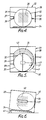
- Figures 4 to 6 show an alternative mixer where the mixing vessel is a sphere 30 made by joining two substantially identical hemispheres 31 and 32. These can be screwed apart, for example, to load the charge to be mixed.
- the size of the sphere 30 will be related as described below to certain features of the interior of a microwave oven 33 in order to achieve the desired composite rotation.
- the oven 33 has a turntable 34, but instead of being horizontal a tilt is imparted, as shown in Figure 6, so that the sphere 30 which rests on the turntable will always tend to roll down towards the front wall 35, its point of contact with the turntable then being off-centre and down the slope.
- a friction pad 36 At the zone of contact with the wall 35, there is a friction pad 36 to promote rotation of the sphere as it is carried round by the turntable in the direction of arrow A.
- the side walls 37 and 38 are also provided with friction pads 39 and 40 respectively.
- the tilt is shown as being imparted by a wedge 41 under the rear of the oven, but there may be more sophisticated arrangements, and an oven could be constructed where its main body would be set level but with its floor and turntable sloping. Also the slope need not be to the front.
- the centre of gravity of the loaded sphere should be at its geometrical centre.
- the charge will be small in relation to the complete sphere, and one solution to this is to fit the two hemispheres 31 and 32 to opposite sides of a disc or "spider" 42, shown in broken lines in Figure 5, at the centre of which there is a capsule 43 or other means of holding the material to be mixed.
- the friction zones are shown shaded when viewed face- on. They may be provided simply by adhesive tape, and in some ovens and with certain container surfaces, it may even be possible to dispense with such measures to enhance the friction.
- This arrangement ensures that, as the turntable rotates, the tendency of the sphere to move with the turntable is partially counteracted by gravity and the friction between the sphere and oven walls.
- the interplay of forces leads to random rotation of the sphere provided that there is enough friction for the forces between the interacting surfaces to be effective to promote rolling, and yet to not such an extent as to prevent some degree of slippage.
- gravity is the simplest means of biassing the sphere towards one wall, it is possible that other means could be used.
- a blower inside the oven could urge the sphere constantly in one direction, or magnetic attraction or repulsion could be employed.
Landscapes
- Chemical & Material Sciences (AREA)
- Chemical Kinetics & Catalysis (AREA)
- Physics & Mathematics (AREA)
- Electromagnetism (AREA)
- Mixers With Rotating Receptacles And Mixers With Vibration Mechanisms (AREA)
Claims (11)
Priority Applications (1)
| Application Number | Priority Date | Filing Date | Title |
|---|---|---|---|
| AT85902594T ATE41607T1 (de) | 1984-05-29 | 1985-05-28 | Mischer zum gebrauch mit einem mikrowellenofen. |
Applications Claiming Priority (4)
| Application Number | Priority Date | Filing Date | Title |
|---|---|---|---|
| GB848413558A GB8413558D0 (en) | 1984-05-29 | 1984-05-29 | Two-plane drum mixer |
| GB8413558 | 1984-05-29 | ||
| GB8425174 | 1984-10-05 | ||
| GB848425174A GB8425174D0 (en) | 1984-10-05 | 1984-10-05 | Multi-plane spherical mixer |
Publications (2)
| Publication Number | Publication Date |
|---|---|
| EP0185697A1 EP0185697A1 (de) | 1986-07-02 |
| EP0185697B1 true EP0185697B1 (de) | 1989-03-22 |
Family
ID=26287789
Family Applications (1)
| Application Number | Title | Priority Date | Filing Date |
|---|---|---|---|
| EP85902594A Expired EP0185697B1 (de) | 1984-05-29 | 1985-05-28 | Mischer zum gebrauch mit einem mikrowellenofen |
Country Status (4)
| Country | Link |
|---|---|
| US (1) | US4714813A (de) |
| EP (1) | EP0185697B1 (de) |
| DE (1) | DE3568947D1 (de) |
| WO (1) | WO1985005560A1 (de) |
Families Citing this family (24)
| Publication number | Priority date | Publication date | Assignee | Title |
|---|---|---|---|---|
| US4822967A (en) * | 1987-03-10 | 1989-04-18 | Toppan Printing Co., Ltd. | Apparatus for sterilizing sealed food stuffs by microwave irradiation |
| WO1989010678A1 (en) * | 1988-04-19 | 1989-11-02 | Deakin University | Improved microwave treatment apparatus |
| US4855555A (en) * | 1988-07-11 | 1989-08-08 | Canadian Patents And Development Limited-Societe Canadienne Des Brevets Et D'exploitation Limitee | Microwave apparatus for thawing frozen liquid and a bag holder assembly for use therein |
| US5206479A (en) * | 1990-05-04 | 1993-04-27 | Cem Corporation | Microwave heating system |
| US5908576A (en) * | 1995-07-18 | 1999-06-01 | Henning; Jeffrey D. | Rotisserie apparatus for microwave oven |
| US5837980A (en) * | 1995-07-18 | 1998-11-17 | Henning; Jeffrey D. | Microwave oven rotisserie and stirring apparatus |
| US5808276A (en) * | 1996-10-28 | 1998-09-15 | Padilla; Ted A. | Device for unattended simultaneous heating and agitating of a bottle of infant formula |
| KR100206366B1 (ko) * | 1996-12-27 | 1999-07-01 | 전주범 | 전자레인지의 고주파 분산구조 |
| RU2158175C1 (ru) * | 2000-02-07 | 2000-10-27 | Егоров Юрий Михайлович | Способ смешивания жидких веществ |
| FR2807307B1 (fr) * | 2000-04-10 | 2003-02-28 | Lmac La Machine A Cafe | Systeme d'accessoires pour une rotissoire |
| DE10037417A1 (de) * | 2000-07-24 | 2002-02-07 | Friedrich Schiller Uni Jena Bu | Vorrichtung zur Durchführung multipler chemischer Reaktionen und Prozesse in Hochfrequenzfeldern |
| US20030127455A1 (en) * | 2002-10-16 | 2003-07-10 | Mr. Glen T. Poss, Gtpgroup | Apparatus and process for roasting coffee beans using a combination of microwave, conduction, convection, and latent steam |
| DE10354109A1 (de) * | 2003-11-19 | 2005-06-23 | Bayer Technology Services Gmbh | Verfahren zum Aufschmelzen von gefrorenen, wasserhaltigen Produkten |
| ATE354441T1 (de) * | 2003-12-17 | 2007-03-15 | Mikrowellen Systeme Mws Gmbh | Vorrichtung zum erhitzen von einem in einem behälter befindlichen stoff |
| US20070145047A1 (en) * | 2005-12-22 | 2007-06-28 | Mickey Ronald G | Thermal processor |
| US7993693B2 (en) * | 2006-07-19 | 2011-08-09 | Frito-Lay Trading Company Gmbh | Process for making a healthy snack food |
| US7695746B2 (en) * | 2006-07-19 | 2010-04-13 | Frito-Lay Trading Company Gmbh | Process for making a healthy snack food |
| US7867533B2 (en) * | 2006-07-19 | 2011-01-11 | Frito-Lay Trading Compnay GmbH | Process for making a healthy snack food |
| US8847131B2 (en) * | 2008-03-03 | 2014-09-30 | Lee Fang | Microwave oven with rotary cooking apparatus |
| GB2481469B (en) | 2011-01-31 | 2013-02-13 | Frito Lay Trading Co Gmbh | De-oiling apparatus and method in the manufacture of low oil potato chips |
| CA2883826A1 (en) * | 2012-10-31 | 2014-05-08 | Pluristem Ltd. | Method and device for thawing biological material |
| CN105080452B (zh) * | 2014-05-08 | 2017-05-17 | 南京三乐微波技术发展有限公司 | 一种微波处理物料用承载体 |
| US9955534B2 (en) | 2015-05-15 | 2018-04-24 | Ck Innovative Microwave Products Llc | Microwave tray and accessories |
| IT201900000469A1 (it) * | 2019-01-11 | 2020-07-11 | Vfg S R L S | Forno a microonde |
Family Cites Families (20)
| Publication number | Priority date | Publication date | Assignee | Title |
|---|---|---|---|---|
| DE371505C (de) * | 1923-06-05 | Alfred Krone | Maschine zum Verreiben und gleichzeitigen Mischen von Stoffen in einer Hohlkugel, welche gleichzeitig um zwei senkrecht zueinander stehende Achsen gedreht wird | |
| US1723145A (en) * | 1928-01-23 | 1929-08-06 | Joseph M Lugo | Barbecue broiler |
| CH444338A (de) * | 1965-05-19 | 1967-09-30 | Patelhold Patentverwertung | Mikrowellenbehandlungsgerät zum Erwärmen von Flüssigkeiten, insbesondere von Blutkonserven |
| US3462575A (en) * | 1967-05-31 | 1969-08-19 | Holaday Ind Inc | Microwave heating device |
| US3473789A (en) * | 1967-11-30 | 1969-10-21 | John S Dietrich | Mixing device |
| US3744403A (en) * | 1972-10-24 | 1973-07-10 | J Castronuovo | Marshmallow toasting device |
| DE2418155A1 (de) * | 1974-04-13 | 1975-12-18 | Bosch Elektronik Gmbh | Zum erwaermen von blut dienendes mikrowellengeraet |
| CA1132534A (en) * | 1978-09-25 | 1982-09-28 | John C. Gall | Material tumbler with non-perpendicular rotation axes |
| US4286133A (en) * | 1979-05-29 | 1981-08-25 | Whirlpool Corporation | Bi-rotational microwave oven turntable/rotisserie |
| US4281936A (en) * | 1979-11-13 | 1981-08-04 | Red Devil, Inc. | Paint mixing and conditioning machine |
| JPS56128592A (en) * | 1980-03-12 | 1981-10-08 | Doryokuro Kakunenryo | Method and device for heating with microwave |
| JPS5733733A (en) * | 1980-08-07 | 1982-02-23 | Toshiba Corp | High-frequency heating device |
| US4446779A (en) * | 1980-12-05 | 1984-05-08 | Hubbard Raymond W | Meat processor |
| US4467163A (en) * | 1981-01-19 | 1984-08-21 | Baxter Travenol Laboratories, Inc. | Temperature sensing system for microwave oven apparatus |
| US4336435A (en) * | 1981-03-23 | 1982-06-22 | Canadian Patents & Dev. Limited | Microwave apparatus for heating liquid in a closed plastic container |
| GB2096909B (en) * | 1981-04-21 | 1984-12-05 | Red Devil Inc | Paint mixing and conditioning machine |
| IT8221696U1 (it) * | 1982-04-27 | 1983-10-27 | Gargioni Domenico | Apparecchio mescolatore particolarmente per la miscelazione di prodotti vernicianti o sospensioni simili |
| US4458128A (en) * | 1983-03-28 | 1984-07-03 | Raytheon Company | Microwave sheet rubber curing |
| US4503307A (en) * | 1983-06-20 | 1985-03-05 | The United States Of America As Represented By The Secretary Of The Navy | Shielding apparatus for microwave thawing |
| US4571474A (en) * | 1984-04-18 | 1986-02-18 | Plastics, Inc. | Microwave oven rotisserie and stirrer |
-
1985
- 1985-05-28 EP EP85902594A patent/EP0185697B1/de not_active Expired
- 1985-05-28 DE DE8585902594T patent/DE3568947D1/de not_active Expired
- 1985-05-28 US US06/823,870 patent/US4714813A/en not_active Expired - Fee Related
- 1985-05-28 WO PCT/GB1985/000226 patent/WO1985005560A1/en not_active Ceased
Also Published As
| Publication number | Publication date |
|---|---|
| WO1985005560A1 (en) | 1985-12-19 |
| DE3568947D1 (en) | 1989-04-27 |
| EP0185697A1 (de) | 1986-07-02 |
| US4714813A (en) | 1987-12-22 |
Similar Documents
| Publication | Publication Date | Title |
|---|---|---|
| EP0185697B1 (de) | Mischer zum gebrauch mit einem mikrowellenofen | |
| US10123656B2 (en) | Three-dimensional stirring/mixing utensils | |
| US4694132A (en) | Microwave oven turntable with removable table top | |
| CN105559518B (zh) | 一种烹饪锅 | |
| US4373029A (en) | Device for cultivation of matrix-bound biologic cell systems | |
| US4036151A (en) | Microwave cooking apparatus with turntable | |
| DK151371B (da) | Apparat til blanding af flydedygtigt materiale i en beholder | |
| US5511879A (en) | Shaker attachement | |
| US4717802A (en) | Microwave oven rotisserie assembly | |
| US4571474A (en) | Microwave oven rotisserie and stirrer | |
| JP2000237566A (ja) | マイクロ波オーブンで使用するための磁気撹拌装置 | |
| US3975001A (en) | Apparatus for mixing fluids held in tubes | |
| KR20190088206A (ko) | 자력을 이용한 동력전달 구조를 구비하는 교반 및 탈포기 | |
| JP2000246082A (ja) | 混合攪拌装置 | |
| US3764112A (en) | Apparatus for mixing the contents within containers | |
| US3785621A (en) | Preparation of mixes | |
| US5593609A (en) | Mixing device for a microwave oven | |
| JP3662600B2 (ja) | 自公転方式マグネチックスターラー | |
| US4042218A (en) | Apparatus for mixing fluids held in tubes | |
| US3439901A (en) | Method and apparatus for agitating material and in particular for tossing salads | |
| JP3116065B2 (ja) | 揺動撹拌装置 | |
| JPH078331B2 (ja) | 攪拌装置 | |
| US2155596A (en) | Means for mixing samples | |
| US2877001A (en) | Food mixer | |
| CN112741123A (zh) | 一种富硒小麦饼干生产用搅拌装置 |
Legal Events
| Date | Code | Title | Description |
|---|---|---|---|
| PUAI | Public reference made under article 153(3) epc to a published international application that has entered the european phase |
Free format text: ORIGINAL CODE: 0009012 |
|
| AK | Designated contracting states |
Kind code of ref document: A1 Designated state(s): AT BE CH DE FR GB IT LI LU NL SE |
|
| 17P | Request for examination filed |
Effective date: 19860610 |
|
| 17Q | First examination report despatched |
Effective date: 19870611 |
|
| GRAA | (expected) grant |
Free format text: ORIGINAL CODE: 0009210 |
|
| AK | Designated contracting states |
Kind code of ref document: B1 Designated state(s): AT BE CH DE FR GB IT LI LU NL SE |
|
| PG25 | Lapsed in a contracting state [announced via postgrant information from national office to epo] |
Ref country code: IT Free format text: LAPSE BECAUSE OF FAILURE TO SUBMIT A TRANSLATION OF THE DESCRIPTION OR TO PAY THE FEE WITHIN THE PRESCRIBED TIME-LIMIT;WARNING: LAPSES OF ITALIAN PATENTS WITH EFFECTIVE DATE BEFORE 2007 MAY HAVE OCCURRED AT ANY TIME BEFORE 2007. THE CORRECT EFFECTIVE DATE MAY BE DIFFERENT FROM THE ONE RECORDED. Effective date: 19890322 Ref country code: CH Effective date: 19890322 Ref country code: SE Effective date: 19890322 Ref country code: BE Effective date: 19890322 Ref country code: AT Effective date: 19890322 Ref country code: LI Effective date: 19890322 |
|
| REF | Corresponds to: |
Ref document number: 41607 Country of ref document: AT Date of ref document: 19890415 Kind code of ref document: T |
|
| REF | Corresponds to: |
Ref document number: 3568947 Country of ref document: DE Date of ref document: 19890427 |
|
| PG25 | Lapsed in a contracting state [announced via postgrant information from national office to epo] |
Ref country code: LU Free format text: LAPSE BECAUSE OF NON-PAYMENT OF DUE FEES Effective date: 19890531 |
|
| ET | Fr: translation filed | ||
| REG | Reference to a national code |
Ref country code: CH Ref legal event code: PL |
|
| PLBE | No opposition filed within time limit |
Free format text: ORIGINAL CODE: 0009261 |
|
| STAA | Information on the status of an ep patent application or granted ep patent |
Free format text: STATUS: NO OPPOSITION FILED WITHIN TIME LIMIT |
|
| 26N | No opposition filed | ||
| PGFP | Annual fee paid to national office [announced via postgrant information from national office to epo] |
Ref country code: FR Payment date: 19920522 Year of fee payment: 8 |
|
| PGFP | Annual fee paid to national office [announced via postgrant information from national office to epo] |
Ref country code: GB Payment date: 19920526 Year of fee payment: 8 |
|
| PGFP | Annual fee paid to national office [announced via postgrant information from national office to epo] |
Ref country code: NL Payment date: 19920531 Year of fee payment: 8 |
|
| PGFP | Annual fee paid to national office [announced via postgrant information from national office to epo] |
Ref country code: DE Payment date: 19920730 Year of fee payment: 8 |
|
| PG25 | Lapsed in a contracting state [announced via postgrant information from national office to epo] |
Ref country code: GB Effective date: 19930528 |
|
| PG25 | Lapsed in a contracting state [announced via postgrant information from national office to epo] |
Ref country code: NL Effective date: 19931201 |
|
| NLV4 | Nl: lapsed or anulled due to non-payment of the annual fee | ||
| GBPC | Gb: european patent ceased through non-payment of renewal fee |
Effective date: 19930528 |
|
| PG25 | Lapsed in a contracting state [announced via postgrant information from national office to epo] |
Ref country code: FR Effective date: 19940131 |
|
| PG25 | Lapsed in a contracting state [announced via postgrant information from national office to epo] |
Ref country code: DE Effective date: 19940201 |
|
| REG | Reference to a national code |
Ref country code: FR Ref legal event code: ST |