EP0185579A1 - Method for displacing a mobile system moved by an electric motor along a given trajectory - Google Patents
Method for displacing a mobile system moved by an electric motor along a given trajectory Download PDFInfo
- Publication number
- EP0185579A1 EP0185579A1 EP85402324A EP85402324A EP0185579A1 EP 0185579 A1 EP0185579 A1 EP 0185579A1 EP 85402324 A EP85402324 A EP 85402324A EP 85402324 A EP85402324 A EP 85402324A EP 0185579 A1 EP0185579 A1 EP 0185579A1
- Authority
- EP
- European Patent Office
- Prior art keywords
- point
- mobile
- current
- motor
- speed
- Prior art date
- Legal status (The legal status is an assumption and is not a legal conclusion. Google has not performed a legal analysis and makes no representation as to the accuracy of the status listed.)
- Granted
Links
Images


Classifications
-
- G—PHYSICS
- G11—INFORMATION STORAGE
- G11B—INFORMATION STORAGE BASED ON RELATIVE MOVEMENT BETWEEN RECORD CARRIER AND TRANSDUCER
- G11B5/00—Recording by magnetisation or demagnetisation of a record carrier; Reproducing by magnetic means; Record carriers therefor
- G11B5/48—Disposition or mounting of heads or head supports relative to record carriers ; arrangements of heads, e.g. for scanning the record carrier to increase the relative speed
- G11B5/54—Disposition or mounting of heads or head supports relative to record carriers ; arrangements of heads, e.g. for scanning the record carrier to increase the relative speed with provision for moving the head into or out of its operative position or across tracks
- G11B5/55—Track change, selection or acquisition by displacement of the head
- G11B5/5521—Track change, selection or acquisition by displacement of the head across disk tracks
- G11B5/5526—Control therefor; circuits, track configurations or relative disposition of servo-information transducers and servo-information tracks for control thereof
- G11B5/553—Details
- G11B5/5547—"Seek" control and circuits therefor
-
- G—PHYSICS
- G08—SIGNALLING
- G08B—SIGNALLING OR CALLING SYSTEMS; ORDER TELEGRAPHS; ALARM SYSTEMS
- G08B1/00—Systems for signalling characterised solely by the form of transmission of the signal
- G08B1/08—Systems for signalling characterised solely by the form of transmission of the signal using electric transmission ; transformation of alarm signals to electrical signals from a different medium, e.g. transmission of an electric alarm signal upon detection of an audible alarm signal
-
- G—PHYSICS
- G11—INFORMATION STORAGE
- G11B—INFORMATION STORAGE BASED ON RELATIVE MOVEMENT BETWEEN RECORD CARRIER AND TRANSDUCER
- G11B5/00—Recording by magnetisation or demagnetisation of a record carrier; Reproducing by magnetic means; Record carriers therefor
- G11B5/48—Disposition or mounting of heads or head supports relative to record carriers ; arrangements of heads, e.g. for scanning the record carrier to increase the relative speed
- G11B5/54—Disposition or mounting of heads or head supports relative to record carriers ; arrangements of heads, e.g. for scanning the record carrier to increase the relative speed with provision for moving the head into or out of its operative position or across tracks
-
- Y—GENERAL TAGGING OF NEW TECHNOLOGICAL DEVELOPMENTS; GENERAL TAGGING OF CROSS-SECTIONAL TECHNOLOGIES SPANNING OVER SEVERAL SECTIONS OF THE IPC; TECHNICAL SUBJECTS COVERED BY FORMER USPC CROSS-REFERENCE ART COLLECTIONS [XRACs] AND DIGESTS
- Y10—TECHNICAL SUBJECTS COVERED BY FORMER USPC
- Y10S—TECHNICAL SUBJECTS COVERED BY FORMER USPC CROSS-REFERENCE ART COLLECTIONS [XRACs] AND DIGESTS
- Y10S388/00—Electricity: motor control systems
- Y10S388/907—Specific control circuit element or device
- Y10S388/915—Sawtooth or ramp waveform generator
Definitions
- the invention relates to a method for moving a mobile system driven by an electric motor along a given trajectory and its implementation device. It is more particularly applicable to systems for moving and loading heads comprising the transducers for reading and writing magnetic disks of a disk memory.
- Each side of a magnetic disc is associated, most often a single read write transducer. So that this transducer can write or read any information contained on the face which is associated with it, it is placed on a platform which is moved parallel to the face of the disc by means of a linear or rotary electrodynamic motor.
- the platform itself is composed of two essential parts, namely on the one hand, a part called the head which includes the transducers and on the other hand a suspension device of which one extremis is solarre of the head and the other end secured to the rigid arm secured to the movable part of the electrodynamic motor
- the head comprising the transducer (s) for reading and writing from one side of a disc is in the form of a relatively flat rectangular parallelepiped, the underside of which is arranged opposite the disc includes the transducer.
- the large upper face parallel to the previous one contains the ends of the electrical input and / or output wires of the transducer and the means making it possible to connect these wires to the electronic reading and / or writing circuits of the disk memory.
- the rotation of the disc causes the existence between the underside of the head of the platform and the face of the disc associated with the transducer thereof, a compressed air cushion which prevents the head from touching the disc and as a result of deteriorating it. It is said that the head flies above the face of the disc associated with it. Under these conditions, the distance between the face of the disc and the underside of the head is called “flight height" h. It should be noted that the head is also called flight pad in current practice.
- the dynamic balance of the platform in flight is obtained by opposing the pressure force created by the air cushion on the surface of the underside of the platform a force called "load” directed in the opposite direction, applied to the upper face of the head and module equal to that of the pressing force.
- the charge is relatively weak, of the order of 1C to is grams. It is provided by a load blade secured to the rigid removable arm.
- a delicate problem to solve is that of the flight of the head.
- the head is in a position located near the periphery of the disk outside of it, called “rest position" for which the distance H between the underside of the head and the plane containing the face of the disc associated with the head is of the order of a few tenths of a millimeter.
- rest position for which the distance H between the underside of the head and the plane containing the face of the disc associated with the head is of the order of a few tenths of a millimeter.
- it is therefore necessary to move it from its rest position outside the disc to the position where it is lowered towards the disc in stable flight position, at a height h of a few tenths of a micron above the surface of the disc.
- the flight is delicate mainly because of the air turbulence near the surface of the disc.
- putting the head in flight consists of moving it from a position where its distance from the disc is H, to a position where it is loaded so that it flies so stable above the surface of the disk, its distance from the latter being h less than H.
- the positioner is mounted on ball bearings.
- the load of each head is supplied, as mentioned above, by a load blade articulated by one of its ends to an arm secured to the rotary positioner and carrying at its other end a suspension device of the head.
- This blade is itself mechanically connected to a wire on which a pusher mounted on the end of a leaf spring articulated on the arm secured to the positioner rests.
- the pusher is in contact with the profile of a fixed cam.
- the profile of this cam comprises two slope breaking points thus dividing it into three distinct parts.
- the displacement and head loading system can be compared to a mobile system that moves along a given trajectory formed by the three parts of the profile of the cam.
- the mobile system constituted by the system of displacement and caressing of heads, with a mobile constituted by the pusher moving along the profile of the cam and having the same mass and same inertia than the head moving and loading system.
- the present invention relates to a first method for moving the mobile system constituted by the system for moving and loading heads along the second part of the profile of the cam between the two break-off points, so that the mobile crosses the second painted slope break with a speed between two predetermined values, the friction forces to which the mobile is subjected being constant for the same course, but may vary from one course to another and from a disk memory to the other.
- the first method according to the invention consists in sending into the motor a succession of current pulses of increasing intensities and of the same duration, called validation duration, and of verifying during each pulse whether the mobile has reached the second point of slope failure.
- the mobile having arrived at this point, its law of movement is modified by sending a braking current in the motor.
- the detection of the passage of the mobile at the second break point is carried out by detecting the variation of acceleration undergone by the mobile at this point. Acceleration is measured by differentiating the electromotive force of the rotary electrodynamic motor using a differentiating circuit.
- the first method for moving a mobile system powered by an electric motor along a given path towards a given destination point thereof, by being subjected to these constant resistant forces during the duration of the same movement but which may vary substantially from one course of the trajectory to another is characterized in that, with the aim of driving the mobile system to the point of destination where the speed is between two predetermined values,
- the speed of the mobile system is incremented by incrementing the current (or voltage) in the motor in successive steps of a validation duration determined by sending a series of current pulses (or voltage) in the latter, checking during the validation period of each pulse if the mobile has passed to the destination point, by sending at the end of this period a new current (voltage) pulse higher than that of the previous one if the mobile has not reached this point at this instant and by ceasing the implementation of the method when the mobile system has reached this point, the value of the validation duration and of the current increment being respectively a function of the length of the journey and of the minimum value on the one hand and the maximum value on the other.
- the speed increment is carried out by sending a succession of current (or voltage) pulses of a first direction in the motor whose value increases in absolute value.
- ACRO rotary actuator has a rotation axis
- the POSROT rotary positioner comprises on the one hand an ARMOB metal frame made of a light metal, and on the other hand the support arm BS (which is seen in more detail shown in perspective in FIG. 3) which carries the DISAD device.
- the DISAD device is controlled by a fixed cam CAM with which it is in contact via the pusher P.
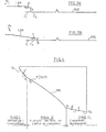
- the cam CAM has a profile which can be seen in more detail in FIG. 4.
- This profile comprises three parts, namely two straight line segments Si and S 2 separated by an arc of a circle AB centered on the axis of rotation ( ⁇ ) of the rotary actuator.
- the straight line segment S 1 is separated from the circular arc AB by the first break point of slope A while the circular arc AB and the second straight line segment S 2 are separated by a second break point from slope B.
- the pusher P which is in contact with the profile of the cam, as shown in FIG. 4, moves along the latter between the points A 'and C.
- the pusher P will move successively over the profile parts A'A, AB and BC.
- the SCT system is immobilized (locked).
- the SCT system is unlocked by sending a current to the ACRO rotary electrodynamic motor.
- the push-button P then moves on the segment Si between the points A 'and A.
- the head T is arranged outside the DISC disc, at a height H above the plane of the DISC disc.
- the pusher P has reached the first break point A begins the second phase described below.
- Phase 2 Approaching the heads in the loading position.
- the pusher P moves from the first break point A to the second break point B by borrowing the second part of the profile of the cam CAM, namely the arc of a circle AB.
- the head T is brought from the position it occupied on the outside of the disc during the locking phase-e to a position located above the disc, opposite the circle C l (see figures lA , lB and 2) located on the periphery of the DISC disk.
- the head T moves parallel to the plane of the disc DISC, that is to say that it remains at a distance H from the plane of the disc.
- the position of the pusher P is such that the leaf spring LRS exerts a thrust on the wire F which in turn exerts a tensile force F T (see FIG. 2A) on the blade loading LAM which thus maintains the head T at a height H from the plane of the disc DISC.
- phase 3 is approached.
- Phase 3 Actual loading.
- the pusher moves from the second break point E to point C on the second line segment S 2 .
- the leaf spring LRS moves away from the edge of the support arm BS, so that the wire F releases its tensile force F T on the load blade LAM, which causes the lowering of the latter towards the disc DISC.
- This causes the loading of the head T on the disc DISC, the distance between the underside of the head T and the disc DISC then being equal to h, flight height of the order of a few tenths of a micron (FIG. 2B), the pusher P having left the surface S 2 of the cam.
- the head is then opposite the circle C 2 (FIGS. 1A, 1B).
- the SCT system is a mobile system moving along a trajectory A'ABC.
- This mobile system is subjected, during the course of the path A'ABC, to resistant forces which, as said above, - remain constant for the same course of the trajectory A'ABC and can vary from one course of the trajectory to another (whether for the same disk memory or for different memories).
- the SCT system by moving the SCT system by means of a control current in the rotary electrodynamic motor having a given intensity and duration, ensuring that this system has correct displacement conditions (i.e. displacement in the minimum time, loading the head T with a speed between two predetermined values given allowing it to be at the required flight altitude without touching the disc), in given environmental conditions, it may be that the same control current, in other environmental conditions, does not allow correct movement of the heads.
- the displacement time may then be too short, the heads being liable to strike the disc, or else the displacement system may fail to cross the second break point B, and then the head T cannot be loaded.
- the first object of the invention relates to a first method for moving a mobile system secured to an electric motor along a given trajectory (AB) overcoming the above drawbacks by moving the mobile according to phase 2 of the movement under the best conditions ( minimum time, assurance that the end point is reached with a speed between two predetermined values), whatever the environmental conditions.
- the second object of the invention also relates to the second method for moving a displacement system and for loading heads secured to an electric motor Following a path dcnarna A'ABC (at two break points) overcoming the drawbacks mentioned above, by moving the system according to all three phases 1, 2, 3 mentioned above.
- Phase 1 (illustrated in FIG. 5A): A current is sent into the armature of the rotary electrodynamic motor in the form of a ramp, the intensity of which increases linearly as a function of time. During this phase, it is constantly checked whether the mobile system constituted by the SCT system passes to point A. A preferred mode of detection of the passage from the mobile system to point A will be described later. This detection mode is identical to the detection mode for the passage of the mobile system at point B. The current ramp begins at time T 0 and ends at time T 1 when the passage of the mobile system has been detected. at point A.
- the time interval T 1 -T 0 is for example of the order of 25 to 30 milliseconds, whereas between the instants T 0 and T 1 , the current intensity varies linearly from 0 to a few hundreds of milliamps (700 milli amps in Figure 5A).
- T l we pass to the second phase corresponding to the implementation of the method according to the invention.
- V 1 and V 2 are determined experimentally.
- ⁇ i The value of ⁇ i is established experimentally and depends on the maximum speed V 2 ⁇ (If ⁇ i is too large, the speed of the mobile system risks exceeding V 2 at the point of break in slope B).
- phase 2 where the method according to the invention is implemented, a succession of pulses of increasing intensity and of the same duration is applied to the armature of the motor, and the application of each pulse if the mobile passes to the destination point B.
- the current is incremented by successive steps of a validation duration t V , which amounts to saying that the speed of the mobile system is incremented by successive steps of the same validation time tV.
- the current pulses have been arbitrarily assumed to be positive.
- a current pulse is sent at instant T ' 4 in the armature of the motor, in the opposite direction to the pulses I 1 , I 2 , I 3 , that is to say negative in the example.
- This time t 4 is of the order of a few tens of milliseconds.
- I F be this braking pulse. Its intensity has been calculated so that it allows immobilization of the mobile system, when the latter has maximum acceleration at point B due to the reaction of the cam on the pusher. This maximum acceleration is determined experimentally.
- the duration t 4 was chosen so that, the acceleration at point B being assumed to be maximum (i.e. the driving force due to the reaction of the cam on the pusher being assumed to be maximum), the intensity being chosen equal to that determined previously (for example of the order of 500 milliamps), the SCT system is immobilized without residual oscillations.
- the duration t 4 corresponds to the duration of the transient regime during which the angular speed ⁇ of the head loading system T passes from the value it had just before the application of the braking pulse, to a zero value (see Figure 6).
- the mobile system is immobilized, it is in equilibrium under the action of the driving force due to the reaction of the cam on the pusher, on the one hand, and the torque on the other hand. resistant exerted by the motor and frictional forces.
- a current decreasing linearly as a function of time is applied to the armature of the motor as indicated for example in FIGS. 5C and 6, the duration of this decreasing current ramp being of the order of 200 at 300 milliseconds.
- This ramp can be obtained, for example, in the form of a succession of ten steps, the duration of each step being of the order of 20 milliseconds.
- the shape of the angular speed is then that indicated in FIG. 6. After a certain time the speed stabilizes and remains substantially constant until the mobile reaches point C. After the last level where the current is zero in the armature of the motor, a short duration positive current pulse is sent so that the displacement and head loading system reaches a predetermined position, the limit point of its trajectory beyond which it cannot move (by construction).
- the variation in acceleration of the mobile system is measured. This is achieved by measuring and then differentiating the counterelectromotive force of the linear electrodynamic motor.
- the threshold value is determined experimentally, so that it is significantly greater than the average acceleration calculated both on the path A'A (to detect the passage at point A) and on the path AB (to detect the go to point B).
- the values of the thresholds for detecting the passage of the mobile system at points A and B are generally different.
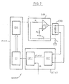
- FIG. 7 An example of a device for implementing the second method for moving the SCT movement and loading system according to phases 1, 2 and 3 according to the invention is shown in FIG. 7.
- the generator GEN includes the amplifier AMP and the three resistors R 1 , R 2 , R 3 .
- the resistor R 3 connects the positive input of the amplifier to ground, while the resistor R l connects the output of the control means MCOM to the negative input of the amplifier AMP, the resistor R 2 connects the input of the generator GEN to one of the terminals of the armature of the ACRO motor, this same terminal being connected via a resistor R 4 to ground.
- the output of AMP is located at the other terminal of the armature of ACRO.
- This generator GEN transforms the voltage pulses it receives from the control means MCOM into current pulses such as those shown in FIGS. 5A, 5B and 5C.
- the control means MCOM include, an instruction generator GI delivering instructions in binary form to a digital analog converter CDA.
- the GI instruction generator in a preferred embodiment of the invention, is a microprocessor containing a firmware delivering a series of binary instructions to the digital analog converter CDA, according to an algorithm which is represented in FIG. 8. At each value binary sent by the instruction generator GI to the digital analog converter CDA corresponds, at the output of the latter, to a voltage pulse, transformed into current pulse by the generator GEN.
- the DIF differentiation means differentiate the electromotive force e taken across the armature of the ACRO motor.
- This comparator sends a linear value 0 to the instruction generator GI, as long as the acceleration remains below the threshold SA, and sends a binary value equal to 1 when the acceleration has exceeded this threshold SA, that is to say when the marrow system has passed either to point A or to point B.
Abstract
Procédé pour déplacer un système mobile (SCT) mu par un moteur électrique suivant une tragectoire donnée (AB) vers un point de destination donné de celle-ci (B) en étant soumis à des efforts résistants constants pour un même déplacement mais variant d'un déplacement à l'autre. Selon l'invention, le procédé est caractérisé en ce qu'on incrémente la vitesse du système mobile (SCT) en incrémentant le courant (ou la tension) dans le moteur, par pas successifs d'une durée de validation déterminée (tv) et on vérifie pendant chaque durée de validation si le mobile passe au point de destination (B). Application: Système de déplacement et de déchargement des têtes d'écriture-lecture de mémoires à disques.Method for moving a mobile system (SCT) driven by an electric motor along a given treadmill (AB) to a given destination point thereof (B) by being subjected to constant resistant forces for the same movement but varying from one move to another. According to the invention, the method is characterized in that the speed of the mobile system (SCT) is incremented by incrementing the current (or the voltage) in the motor, by successive steps of a determined validation duration (tv) and during each validation period, it is checked whether the mobile passes to the destination point (B). Application: System for moving and unloading the write-read heads of disk memories.
Description
L'invention concerne un procédé pour déplacer un système mobile mu par un moteur électrique suivant une trajectoire donnée et son dispositif de mise en oeuvre. Elle est plus particulièrement applicable aux systèmes de déplacement et de chargement de têtes comportant les transducteurs de lecture écriture des disques magnétiques d'une mémoire à disques.The invention relates to a method for moving a mobile system driven by an electric motor along a given trajectory and its implementation device. It is more particularly applicable to systems for moving and loading heads comprising the transducers for reading and writing magnetic disks of a disk memory.
On sait que, dans les mémoires à disques magnétiques, les informations sont écrites (ou lues) sur des pistes concentriques circulaires par des transducteurs de lecture/ écriture qui sont disposés à très faible distance de chacune des faces des disques et qui peuvent se déplacer au-dessus de celles-ci de manière à écrire (ou lire) l'ensemble des pistes contenues sur chacune des faces. Lors de ces opérations d'écriture et de lecture, les disques ont une vitesse de rotation constante.We know that, in magnetic disk memories, the information is written (or read) on circular concentric tracks by read / write transducers which are arranged at very short distance from each of the faces of the disks and which can move at above them so as to write (or read) all of the tracks contained on each of the faces. During these write and read operations, the discs have a constant rotational speed.
A chaque face d'un disque magnétique, est associé, le plus souvent un seul transducteur d'écriture lecture. Pour que ce transducteur puisse écrire ou lire n'importe quelle information contenue sur la face qui lui est associée, il est disposé sur une plate-forme qui est déplacée parallèlement à la face du disque au moyen d'un moteur électrodynamique linéaire ou rotatif.Each side of a magnetic disc is associated, most often a single read write transducer. So that this transducer can write or read any information contained on the face which is associated with it, it is placed on a platform which is moved parallel to the face of the disc by means of a linear or rotary electrodynamic motor.
La plate-forme elle-même se compose ce deux parties essentielles, à savoir d'une part, une partie appelée tête qui comprend les transducteurs et d'entre part un dispositif de sussension dont une extrémis est solarre de la tête et l'autre extrémité solidaire d bras rigice solidaire de la partie mobile du moteur électrodynamiqueThe platform itself is composed of two essential parts, namely on the one hand, a part called the head which includes the transducers and on the other hand a suspension device of which one extremis is solarre of the head and the other end secured to the rigid arm secured to the movable part of the electrodynamic motor
Généralement, la tête comportant le(s) transducteur(s) de lecture écriture d'une face d'un disque a is forme d'un parallélépipède rectangle relativement plat dont la face inférieure disposée en regard du disque comporte le transducteur. La grande face supérieure parallèle à la précédente contient les extrémités des .fils électriques d'entrée et/ou sortie du transducteur et les moyens permettant de connecter ces fils aux circuits électroniques de lecture et/ou écriture de la mémoire à disques.Generally, the head comprising the transducer (s) for reading and writing from one side of a disc is in the form of a relatively flat rectangular parallelepiped, the underside of which is arranged opposite the disc includes the transducer. The large upper face parallel to the previous one contains the ends of the electrical input and / or output wires of the transducer and the means making it possible to connect these wires to the electronic reading and / or writing circuits of the disk memory.
Une plate-forme de ce genre est décrite dans le brevet français N° 2.426.943 déposée le 26 Mai 1978 sous le titre "Plate-forme d'au moins un transducteur de lecture et/ou d'enregistrement d'un support d'informations".A platform of this kind is described in French patent No. 2,426,943 filed on May 26, 1978 under the title "Platform of at least one transducer for reading and / or recording a support of information. "
La rotation du disque provoque l'existence entre la face inférieure de la tête de la plate-forme et la face du disque associée au transducteur de celle-ci, d'un coussin d'air comprimé qui empêche la tête de toucher le disque et par suite de le détériorer. On dit alors que la tête vole au-dessus de la face du disque qui lui est associée. Dans ces conditions, la distance entre la face du disque et la face inférieure de la tête est appelée "hauteur de vol" h. Il est à noter que la tête est également appelée patin de vol dans la pratique courante.The rotation of the disc causes the existence between the underside of the head of the platform and the face of the disc associated with the transducer thereof, a compressed air cushion which prevents the head from touching the disc and as a result of deteriorating it. It is said that the head flies above the face of the disc associated with it. Under these conditions, the distance between the face of the disc and the underside of the head is called "flight height" h. It should be noted that the head is also called flight pad in current practice.
L'équilibre dynamique de la plate-forme en vol est obtenu en opposant à la force de pression créée par le coussin d'air sur la surface de la face inférieure de la plate-forme une force dite "charge" dirigée en sens inverse, appliquée sur la face supérieure de la tête et de module égal à celui de la force de pression.The dynamic balance of the platform in flight is obtained by opposing the pressure force created by the air cushion on the surface of the underside of the platform a force called "load" directed in the opposite direction, applied to the upper face of the head and module equal to that of the pressing force.
La charge est relativement faiole, de l'ordre de 1C à is grammes. Elle est fournie par une lame de charge solidaire du bras amovible rigide.The charge is relatively weak, of the order of 1C to is grams. It is provided by a load blade secured to the rigid removable arm.
Un problème délicat à résoudre est celui de la mise en vol de la tête. En effet, lorsque la mémoire à disques ne fonctionne pas, la tête se trouve dans une position située au voisinage de la périphérie du disque à l'extérieur de celui-ci, appelée "position de repos" pour laquelle la distance H entre la-face inférieure de la tête et le plan contenant la face du disque associée à la tête, est de l'ordre de quelques dixièmes de millimètres. Pour permettre la mise en vol de la tête, il convient donc de la déplacer depuis sa position de repos à l'extérieur du disque jusqu'à la position où elle est abaissée vers le disque en position de vol stable, à une hauteur h de quelques dixièmes de microns au-dessus de la surface du disque.A delicate problem to solve is that of the flight of the head. In fact, when the disk memory does not work, the head is in a position located near the periphery of the disk outside of it, called "rest position" for which the distance H between the underside of the head and the plane containing the face of the disc associated with the head is of the order of a few tenths of a millimeter. To allow the flight of the head, it is therefore necessary to move it from its rest position outside the disc to the position where it is lowered towards the disc in stable flight position, at a height h of a few tenths of a micron above the surface of the disc.
La mise en vol est délicate en raison principalement des turbulences de l'air au voisinage de la surface du disque.The flight is delicate mainly because of the air turbulence near the surface of the disc.
En d'autres termes, mettre en vol la tête consiste à déplacer celle-ci d'une position où sa distance par rapport au disque est H, jusqu'à une position où on effectue son chargement de telle sorte qu'elle vole de façon stable au-dessus de la surface du disque, sa distance par rapport à ce dernier étant alors h inférieure à H.In other words, putting the head in flight consists of moving it from a position where its distance from the disc is H, to a position where it is loaded so that it flies so stable above the surface of the disk, its distance from the latter being h less than H.
Dans la pratique courante, on utilise de plus en plus fréquemment des systèmes de déplacement et de de chargement de têtes comprenant un positionneur rotatif (bras rotatif), solidaire de la partie mobile d'un moteur électrodynamique rotatif et un dispositif de chargement/déchargemene des têtes permettant soit d'abaisser la tête vers le disque en position de vol, soit de remonter la tête de sa position de vol à sa position de repos. Un tel système est par exemple décrit dans la demande de brevet française N° 82.04349 déposée le 15 Mars 1982 par la Compagnie Internationale pour l'Informatique CII Honeywell Bull sous le titre "Dispositif de chargement de corps principal de plate-forme comportant au moins un transducteur de lecture/écriture d'un support d'informations".In current practice, it is more and more frequently used systems for moving and loading heads comprising a rotary positioner (rotary arm), integral with the mobile part of a rotary electrodynamic motor and a device for loading / unloading heads allowing either to lower the head towards the disc in flight position, or to raise the head from its flight position to its rest position. Such a system is for example described in the French patent application N ° 82.04349 filed on March 15 1982 by the CII Honeywell Bull International Company for Computing under the title "Platform main body loading device comprising at least one read / write transducer for an information medium".
Dans un tel système de déplacement et de chargement de têtes, le positionneur est monté sur roulements à billes. La charge de chaque tête est fournie, ainsi qu'il a été mentionné plus haut, par une lame de charge s'articulant par l'une de ses extrémités à un bras solidaire du positionneur rotatif et portant à son autre extrémité un dispositif de suspension de la tête. Cette lame est elle-même reliée mécaniquement à un fil sur lequel s'appuie un poussoir monté à l'extrémité d'une lame-ressort articulée sur le bras solidaire du positionneur. Le poussoir est en contact avec le profil d'une came fixe. Dans un mode de réalisation préféré, le profil de cette came comprend deux points de rupture de pente le divisant ainsi en trois parties distinctes.In such a displacement and head loading system, the positioner is mounted on ball bearings. The load of each head is supplied, as mentioned above, by a load blade articulated by one of its ends to an arm secured to the rotary positioner and carrying at its other end a suspension device of the head. This blade is itself mechanically connected to a wire on which a pusher mounted on the end of a leaf spring articulated on the arm secured to the positioner rests. The pusher is in contact with the profile of a fixed cam. In a preferred embodiment, the profile of this cam comprises two slope breaking points thus dividing it into three distinct parts.
Le déplacement et le chargement d'une tête s'effectue en trois phases successives, chaque phase correspondant à une position du poussoir sur l'une des trois parties du profil de la came. Ces trois phases sont les suivantes :
- -
Phase 1. Lorsque le poussoir est en contact avec la première partie du profil de la came, le positionneur rotatif d'abord immobilisé est ensuite libéré. Cette phase est dite phase de déverrouillage; - -
Phase 2. Le positionneur ayant été déverrouillé, le poussoir est alors en contact avec la partie centrale du profil ce la came. Lorsque le poussoir se déplace le long de cette partie centrale, le positionneur rotatif effectue une rotation qui amène la tête d'une position située à l'extérieur du disque à une position située au-dessus du disque, à la périphérie de celui-ci, la hauteur de la tête par rapport au plan du disque étant toujours égale à H; - -
Phase 3. Durant cette phase, le poussoir se déplace le long de la troisième partie du profil de la came. L'effort de traction exercée par le poussoir sur la lame de charge diminue progressivement de telle sorte que celle-ci s'abaisse progressivement vers le disque. Elle entraîne de ce fait la tête vers ce dernier, de manière à ce que, lorsque le poussoir arrive en fin de course sur cette troisième partie, la tête se trouve en position de vol stable au-dessus du disque à la hauteur de vol h. Dès que la tête a atteint sa position de vol stable au-dessus du disque, on dit que la tête est chargée. Dans ces conditions, le poussoir n'est plus en contact avec le profil de la came. Cette troisième phase qui est celle de la mise en position de vol stable de la tête au-dessus du disque est donc celle du chargement de la tête proprement dit.
- -
Phase 1. When the pusher is in contact with the first part of the cam profile, the initially stationary rotary positioner is then released. This phase is called the unlocking phase; - -
Phase 2. The positioner having been unlocked, the pusher is then in contact with the central part of the profile, the cam. When the pusher moves along this central part, the rotary positioner performs a rotation which brings the head from a position located outside the disc to a position located above the disc, on the periphery thereof , the height of the head with respect to the plane of the disc being always equal to H; - -
Phase 3. During this phase, the pusher moves along the third part of the cam profile. The tensile force exerted by the pusher on the loading blade progressively decreases so that the latter gradually descends towards the disc. It therefore drives the head towards the latter, so that, when the pusher reaches the end of its travel on this third part, the head is in stable flight position above the disc at the flight height h . As soon as the head has reached its stable flight position over the disc, the head is said to be loaded. Under these conditions, the pusher is no longer in contact with the profile of the cam. This third phase, which is that of putting the head in a stable flight position above the disc, is therefore that of loading the head itself.
Il est clair que, réciproquement, c'est-à-dire pour décharger la tête es la ramener à sa position de repos, les opérations se déroulent exactement d'une manière inverse à celles des opérations de chargement. La première phase correspondant à la phase de chargement lors de la mise en vol s'appelant alors "phase de déchargement".It is clear that, conversely, that is to say to unload the head and return it to its rest position, the operations take place in exactly the opposite way to those of the loading operations. The first phase corresponding to the loading phase during the start-up then being called "unloading phase".
Au vu de ce qui orécède, en voit que l'on peut assimiler le système de déplacement et de chargement de tête à un système mobile qui se déplace le long d'une trajectoire donnée constituée par les trois parties du profil de la came. Pour simplifier le raiscnnement, on assimilera, par la sulte, le système mobile constitué par le système de déplacement et de charcement de têtes, à un mobile constitué par le poussoir se déplacant le long du profil de la came et ayant même masse et même inertie que le système de déplacement et de chargement de têtes.In view of the above, we can see that the displacement and head loading system can be compared to a mobile system that moves along a given trajectory formed by the three parts of the profile of the cam. To simplify the reasoning, we will assimilate, by the sulte, the mobile system constituted by the system of displacement and caressing of heads, with a mobile constituted by the pusher moving along the profile of the cam and having the same mass and same inertia than the head moving and loading system.
Pour une même mémoire à disques, en passant d'un parcours de la trajectoire effectué par le mobile à un autre, on constate que les efforts résistants provoqués par les forces de frottement qui s'opposent au mouvement du mobile le long du profil de la came peuvent varier, dans une proportion de 50% : ainsi, ces forces de frottement peuvent varier de 10 à 15 grammes d'un parcours à l'autre pour une même machine. Des constatations analogues peuvent être faites pour des mémoires à disques différentes. Ces variations sont dues essentiellement aux variations des conditions d'environnement : température, hygrométrie, taux d'électricité statique dans l'air etc....For the same disk memory, passing from one course of the trajectory carried out by the mobile to another, it can be seen that the resistant forces caused by the friction forces which oppose the movement of the mobile along the profile of the cam can vary, in a proportion of 50%: thus, these friction forces can vary from 10 to 15 grams from one course to another for the same machine. Similar observations can be made for different disk memories. These variations are mainly due to variations in the environmental conditions: temperature, humidity, static electricity rate in the air, etc.
Pour ce qui est du déplacement du mobile le long du profil de la came, il y a lieu de résoudre les principaux problèmes suivants, dus essentiellement à ces variations :
- 1. Lors de la phase de déverrouillage du mobile, c'est-à-dire lorsqu'il doit quitter la première partie du profil de la came pour passer sur la seconde partie, en franchissant le premier point de rupture de pente, il convient de vérifier que ce premier point a été effectivement franchi. En effet, en raison des variations possibles de forces de frottement d'un parcours effectué par le mobile à un autre, la probabilité existe que, dans les mêmes conditions de fonctionnement du moteur électrodynamique (même courant et même tension d'alimentation) le premier point de rupture de pente soit franchi lors d'un parcours et ne le soit pas dans l'autre (dans ce dernier cas, il convient de modifier les conditions de fonctionnement du moteur).
- 2. Lorsque le mobile se déplace sur la seconde partie du profil, il convient que le mobile passe au second point de rupture de pente avec une vitesse comprise entre deux valeurs prédéterminées. En effet, si la vitesse du mobile est inférieure à une première valeur prédéterminée, le risque existe d'un retour en arrière du mobile. D'autre part, si la vitesse du mobile au second point de rupture de pente est supérieure à une seconde valeur prédéterminée plus grande que la première, le risque existe que l'énergie du mobile soit telle que, lors du chargement de la tête, la vitesse de celle-ci soit trop grande. Dans ces conditions, la probabilité existe que la tête vienne heurter le disque provoquant alors un endommagement aussi bien du disque que de la tête elle-même.
- 3. Dans la troisième partie, au moment du chargement de la tête le mobile doit avoir une vitesse comprise entre deux valeurs déterminées (par exemple entre 8 et 16 mm par seconde). En effet, si la vitesse est trop grande, le risque existe que la tête vienne percuter le disque et si la vitesse est trop faible, le mobile est animé d'un mouvement d'oscillation pouvant, lui aussi , entraîner le choc de la tête sur le disque.
- 1. During the unlocking phase of the mobile, that is to say when it must leave the first part of the profile of the cam to pass on the second part, crossing the first point of break in slope, it is advisable to verify that this first point has been effectively crossed. Indeed, due to the possible variations of friction forces from one course made by the mobile to another, the probability exists that, under the same operating conditions of the electrodynamic motor (same current and same supply voltage) the first slope break point is crossed during one course and is not crossed in the other (in the latter case, the engine operating conditions should be modified).
- 2. When the mobile moves on the second part of the profile, the mobile should pass to the second break point with a speed between two predetermined values. Indeed, if the speed of the mobile is less than a first predetermined value, the risk exists of a backward movement of the mobile. On the other hand, if the speed of the mobile at the second break point is greater than a second predetermined value greater than the first, the risk exists that the energy of the mobile is such that, when the head is loaded, the speed of the latter is too great. Under these conditions, the probability exists that the head strikes the disc, causing damage to both the disc and the head itself.
- 3. In the third part, when the head is loaded, the mobile must have a speed between two determined values (for example between 8 and 16 mm per second). In fact, if the speed is too high, there is a risk that the head will strike the disc and if the speed is too low, the mobile is animated by an oscillating movement which can also cause the shock of the head on the disc.
Dans cette troisième partie, on doit donc déplacer le mobile en contrôlant sa vitesse alors que celui-ci, à partir du franchissement du second point de rupture ce pente est soumis brusquement à une force motrice due à la réaction de la came sur le poussoir tendant à provoquer une accélération brutale de celui-ci.In this third part, we must move the mobile by controlling its speed while the latter, from the crossing of the second breaking point this slope is suddenly subjected to a driving force due to the reaction of the cam on the tappet to cause a sudden acceleration of it.
La présente invention concerne un premier procédé pour déplacer le système mobile constitué par le système de déplacement et de chargement de têtes le long de la seconde partie du profil de la came entre les deux points de rupture de pente, de telle façon que le mobile franchisse le second peint de rupture de pente avec une vitesse comprise entre deux valeurs prédéterminées, les forces de frottement auxquelles est soumis le mobile étant constantes pour un même parcours, mais pouvant varier d'un parcours à l'autre et d'une mémoire à disque à l'autre.The present invention relates to a first method for moving the mobile system constituted by the system for moving and loading heads along the second part of the profile of the cam between the two break-off points, so that the mobile crosses the second painted slope break with a speed between two predetermined values, the friction forces to which the mobile is subjected being constant for the same course, but may vary from one course to another and from a disk memory to the other.
Le procédé consistant à déplacer le mobile le long de la troisième partie de telle façon que lors de l'atterrissage de la tête, ce dernier ait une vitesse comprise entre deux valeurs prédéterminées, est décrit et revendiqué dans une demande de brevet déposée conjointement à celle-ci par la Compagnie demanderesse.The method of moving the mobile along the third part so that during the landing of the head, the latter has a speed between two predetermined values, is described and claimed in a patent application filed jointly with that - by the Applicant Company.
Au vu de ce qui précède, on voit que durant le parcours de la seconde partie du profil de la came, entre les deux points de rupture de pente, le mobile est soumis d'une part à la force d'entraînement que le moteur électrodymanique rotatif exerce sur le mobile, et d'autre part aux forces de frottement.In view of the foregoing, it can be seen that during the travel of the second part of the profile of the cam, between the two break point of slope, the mobile is subjected on the one hand to the driving force that the electro-mechanical motor rotary exerts on the mobile, and on the other hand to the friction forces.
Le premier procédé selon l'invention consiste à envoyer dans le moteur une succession d'impulsions de courant d'intensités croissantes et de même durée, dite durée de validation, et de vérifier lors de chaque impulsion si le mobile est parvenu au second point de rupture de pente. Le mobile étant parvenu en ce point, on modifie sa loi de mouvement en envoyant un courant de freinage dans le moteur. Dans un mode de réalisation préféré de l'invention, la détection du passage du mobile au second point de rupture de pente, s'effectue en détectant la variation d'accélération subie par le mobile en ce point. L'accélération est mesurée en différentiant la force contre électromotrice du moteur électrodynamique rotatif grâce à un circuit différentiateur. Ainsi, on s'affranchit de la nécessité d'équiper la mémoire à disques d'un système de détection de passage du mobile au second point de rupture de pente, extérieur au système de chargement. En d'autres termes, il n'y a donc pas lieu d'équiper la mémoire à disques d'un capteur de détection spécial pour détecter le passage du mobile au second point de rupture de pente.The first method according to the invention consists in sending into the motor a succession of current pulses of increasing intensities and of the same duration, called validation duration, and of verifying during each pulse whether the mobile has reached the second point of slope failure. The mobile having arrived at this point, its law of movement is modified by sending a braking current in the motor. In a preferred embodiment of the invention, the detection of the passage of the mobile at the second break point, is carried out by detecting the variation of acceleration undergone by the mobile at this point. Acceleration is measured by differentiating the electromotive force of the rotary electrodynamic motor using a differentiating circuit. Thus, it eliminates the need to equip the disk memory with a system for detecting the passage of the mobile at the second break point, outside the loading system. In other words, there is therefore no need to equip the disc memory with a special detection sensor to detect the passage of the mobile at the second break point.
Selon l'invention, le premier procédé pour déplacer un système mobile mû par un moteur électrique suivant une trajectoire donnée vers un point de destination donné de celle-ci, en étant soumis à ces efforts résistants constants pendant la durée du même déplacement mais pouvant varier sensiblement d'un parcours de la trajectoire à l'autre, est caractérisé en ce que, dans le but de conduire le système mobile au point de destination où la vitesse est comprise entre deux valeurs prédéterminées,According to the invention, the first method for moving a mobile system powered by an electric motor along a given path towards a given destination point thereof, by being subjected to these constant resistant forces during the duration of the same movement but which may vary substantially from one course of the trajectory to another, is characterized in that, with the aim of driving the mobile system to the point of destination where the speed is between two predetermined values,
On incrémente la vitesse du système mobile en incrémentant le courant (ou la tension) dans le moteur par pas successifs d'une durée de validation déterminée par envoi d'une suite d'impulsions de courant (ou tension) dans ce dernier, en vérifiant pendant la durée de validation de chaque impulsion si le mobile est passé au point de destination, en envoyant à la fin de cette durée une nouvelle impulsion de courant (tension) supérieure à celle de la précédente si le mobile n'est pas parvenu en ce point à cet instant et en cessant la mise en oeuvre du procédé lorsque le système mobile est parvenu en ce point, la valeur de la durée de validation et de l'incrément de courant étant respectivement fonction de la longueur du parcours et de la valeur minimum d'une part et de la valeur maximum d'autre part.The speed of the mobile system is incremented by incrementing the current (or voltage) in the motor in successive steps of a validation duration determined by sending a series of current pulses (or voltage) in the latter, checking during the validation period of each pulse if the mobile has passed to the destination point, by sending at the end of this period a new current (voltage) pulse higher than that of the previous one if the mobile has not reached this point at this instant and by ceasing the implementation of the method when the mobile system has reached this point, the value of the validation duration and of the current increment being respectively a function of the length of the journey and of the minimum value on the one hand and the maximum value on the other.
Lorsque le moteur est électrodynamique, l'incrémentation de vitesse s'effectue en envoyant une succession d'impulsions de courant (ou tension) d'un premier sens dans le moteur dont la valeur croît en valeur absolue.When the motor is electrodynamic, the speed increment is carried out by sending a succession of current (or voltage) pulses of a first direction in the motor whose value increases in absolute value.
Dans un mode de réalisation préféré de l'inventicn, le mobile étant soumis au point de destination à une accélération instantanée, on détecte le passage du système mobile en ce point en mesurant l'accélération de ce système, puis en la comparant à une valeur prédéterminée. L'invention concerne également un second procédé pour déplacer un système de déplacement et de chargement au moins une tête comportant au moins un transducteur de lecture-écriture d'un disque magnétique, le système mû par un moteur électrodynamique, partant d'un point où il est verrouillé, se déplaçant le long d'une came à deux points de rupture de pente ce qui définit une trajectoire en trois parties successives et étant soumis à des efforts résistants qui restent constants pendant la durée d'un même déplacement mais peuvent varier sensiblement d'un déplacement à l'autre, le procédé étant caractérisé en ce que, dans le but d'amener le système au point d'arrivée où les têtes sont abaissées vers le disque en position de vol au-dessus de celui-ci, avec une vitesse comprise entre une valeur minimum et une valeur maximum, on effectue dans l'ordre les opérations suivantes:
- - 1. On déverrouille le système en envoyant un courant d'intensité croissante dans le moteur jusqu'à ce qu'on détecte le passage du système mobile au premier point de rupture de pente de la came ,
- - 2. On incrémente la vitesse du système par incrémentation du courant (ou de la tension) dans le moteur par pas successifs d'une durée de validation prédéterminée, par envoi d'une suite d'impulsions de courant (ou tension) de même sens, en vérifiant, pendant la durée de validation de chaque impulsion si le système est passé au second point de rupture de pente, en envoyant à la fin de cette durée une nouvelle impulsion de courant supérieure (en valeur absolue) à la précédente si le système n'est pas parvenu en ce point à cet instant, la valeur de la durée de validation et de l'incrément de courant étant respectivement fonction de la longueur du parcours et de la valeur minimum d'une part et de la valeur maximum d'autre part,
- - 3. On donne au système, lorsqu'on a détecté son passage au second point de rupture de pente, une vitesse de référence donnée, par l'envoi d'un courant de commande uans le moteur permettant à celui-ci d'opposer un effort résistant à la force motrice, le sytème étant soumis dès le franchissement du second point de rupture à une force dont l'intensité décroît en fonction de la distance par rapport à celui-ci,
- - 4. On contrôle la vitesse du système par l'envoi dans le moteur d'un courant décroissant (en valeur absolue) à partir de la valeur du courant de commande suivant une loi telle que le mobile parvienne au point d'arrivée avec une vitesse comprise ehtre lesdites valeurs minimum et maximum.
- - 1. The system is unlocked by sending a current of increasing intensity into the motor until the passage of the mobile system is detected at the first point of break in slope of the cam,
- - 2. The system speed is incremented by incrementing the current (or voltage) in the motor in successive steps of a predetermined validation period, by sending a series of current (or voltage) pulses in the same way sense, by checking, during the validation period of each pulse if the system has passed to the second break point, by sending at the end of this period a new current pulse higher (in absolute value) than the previous one if the system has not reached this point at this time, the value of the validation duration and the current increment being respectively a function of the length of the course and the minimum value on the one hand and the maximum value d 'somewhere else,
- - 3. We give to the system, when we have detected its passage at the second break point, a given reference speed, by sending a control current in the motor allowing it to oppose a force resistant to the driving force, the system being subjected as soon as it is crossed from the second breaking point to a force whose intensity decreases as a function of the distance from it,
- - 4. The speed of the system is controlled by sending a decreasing current (in absolute value) to the motor from the value of the control current according to a law such that the mobile arrives at the point of arrival with a speed included between said minimum and maximum values.
D'autres caractéristiques et avantages de la présente invention apparaîtront à la lecture de la description suivante, donnés à titre d'exemple, purement illustratifs et nullement limitatifs, en référence aux dessins annexés sur lesquels:
- - la figure 1 : composée des figures 1A et 1B, montre la disposition relative du moteur électrodynamique linéaire, du système de déplacement et de chargement de têtes de la came, et du disque, dans les deux cas suivants :
- -lorsque la tête n'est pas chargée (n'est pas en position de vol) au-dessus du disque (figure lA),
- -lorsque la tête est chargée (en position de vol au-dessus du disque) (figure 1B).
- - la figure 2 : composée des figures 2A et 2B est une vue de profil simplifiée montrant la position relative de la tête et du disque :
- -lorsque la tête n'est pas chargée (figure 2A) ;
- -lorsque la tête est chargée (figure 2B).
- - la ficure 3 : est une vue de profil en perspective montrant le détail d'une partie du système de déplacemns et de chargement de tête ;
- - la figure 4 : est une vue détaillée de la came montrant son profil en trois parties avec deux points de rupture de pente ;
- - la figure 5; composée des figures 5A, 53 et 5C montre, l'évolution du courant I dans le moteur électrodynamique rotatif, lors du déplacement du système de déplacement et de chargement le long de la came ;
- - la figure 5A : montrant l'évolution du courant dans le moteur lors du déverrouillage du système de déplacement et de chargement;
- - la figure 5B : montrant l'évolution du courant dans le moteur lorsque le système de déplacement et de chargement (le mobile) se déplace le long de la came entre les deux points de rupture de pente, selon le procédé selon l'invention ;
- - la figure 5C : montre l'évolution du courant dans le moteur, à partir du moment où le système de déplacement et de chargement a franchi le second point de rupture de pente;
- - la figure 6 : montre comment est établie expérimentalement la durée du courant de freinage dans le moteur, à partir du moment où le système de déplacement et de chargement a franchi le second point de rupture de pente ;
- - la figure 7 : est un schéma fonctionnel du dispositif de mise en oeuvre du procédé pour déplacer un système de déplacement et de chargement de têtes selon l'invention;
- - la figure 8 : montre l'algorithme de fonctionnement du dispositif montré à la figure 7.
- FIG. 1: made up of FIGS. 1A and 1B, shows the relative arrangement of the linear electrodynamic motor, of the system for moving and loading the heads of the cam, and of the disc, in the following two cases:
- -when the head is not loaded (not in flight position) above the disc (Figure lA),
- -when the head is loaded (in flight position above the disc) (Figure 1B).
- - Figure 2: composed of Figures 2A and 2B is a simplified profile view showing the relative position of the head and the disc:
- -when the head is not loaded (Figure 2A);
- -when the head is loaded (Figure 2B).
- - Figure 3: is a perspective side view showing the detail of part of the displacement system and head loading;
- - Figure 4: is a detailed view of the cam showing its three-part profile with two break points of slope;
- - Figure 5; composed of FIGS. 5A, 53 and 5C shows, the evolution of the current I in the rotary electrodynamic motor, during the displacement of the displacement and loading system along the cam;
- - Figure 5A: showing the evolution of the current in the motor when unlocking the movement and loading system;
- - Figure 5B: showing the evolution of the current in the motor when the displacement and loading system (the mobile) moves along the cam between the two break points, according to the method according to the invention;
- - Figure 5C: shows the evolution of the current in the motor, from the moment when the displacement and loading system has crossed the second break point;
- - Figure 6: shows how is established experimentally the duration of the braking current in the motor, from the moment when the displacement and loading system has crossed the second break point;
- - Figure 7: is a block diagram of the device for implementing the method for moving a head displacement and loading system according to the invention;
- - Figure 8: shows the operating algorithm of the device shown in Figure 7.
Afin de mieux comprendre le procédé selon l'invention, il est utile de rappeler comment est constitué un système de déplacement et de chargement de tête et comment il fonctionne.In order to better understand the method according to the invention, it is useful to recall how a head displacement and loading system is made up and how it works.
On considèrera, pour ce faire, les figures 1, 2, 3,To do this, we will consider Figures 1, 2, 3,
Le système de déplacement et de chargement- de tête SCT comprend, ainsi qu'on peut Le voir sur ces mêmes figures,
- - un positionneur rotatif POSROT solidaire mécaniquement de l'arbre d'entraînement ARBE d'un moteur électrodynamique rotatif ACRO,
- - un dispositif de chargement et de déplacement de la tête T, à savoir DISAD,
- - la came fixe CAM.
- - a POSROT rotary positioner mechanically secured to the ARBE drive shaft of an ACRO rotary electrodynamic motor,
- a device for loading and moving the head T, namely DISAD,
- - the fixed CAM cam.
L'actionneur rotatif ACRO a un axe de rotationACRO rotary actuator has a rotation axis
Le positionneur rotatif POSROT comprend d'une part une armature métallique ARMOB réalisée en un métal léger, et d'autre part le bras support BS (qu'on voit plus en détail représenté en perspective à la figure 3) qui porte le dispositif DISAD.The POSROT rotary positioner comprises on the one hand an ARMOB metal frame made of a light metal, and on the other hand the support arm BS (which is seen in more detail shown in perspective in FIG. 3) which carries the DISAD device.
Le dispositif DISAD comprend :
- -la lame de charge LAM de la tête T à laquelle est lié mécaniquement un dispositif de suspension de la tête T, non visible à la figure 3,
- - le fil F en contact avec la lame ressort LRS. Cette dernière est munie en son extrémité d'un poussoir P et elle est fixée sur le bras support BS.
- the LAM load blade of the head T to which a head T suspension device is mechanically linked, not visible in FIG. 3,
- - wire F in contact with the LRS leaf spring. The latter is provided at its end with a pusher P and it is fixed to the support arm BS.
Le dispositif DISAD est commandé par une came fixe CAM avec laquelle il est en contact par l'intermédiaire du poussoir P.The DISAD device is controlled by a fixed cam CAM with which it is in contact via the pusher P.
La came CAM présente un profil qu'on voit plus en détail à la figure 4. Ce profil comprend trois parties, à savoir deux segments de droite Si et S2 séparés par un arc de cercle AB centré sur l'axe de rotation(Δ) de l'actionneur rotatif. Le segment de droite S1 est séparé de l'arc de cercle AB par an premier point de rupture de pente A alors que l'arc de cercle AB et le second segment de droite S2 sont séparés par un second point de rupture de pente B.The cam CAM has a profile which can be seen in more detail in FIG. 4. This profile comprises three parts, namely two straight line segments Si and S 2 separated by an arc of a circle AB centered on the axis of rotation (Δ ) of the rotary actuator. The straight line segment S 1 is separated from the circular arc AB by the first break point of slope A while the circular arc AB and the second straight line segment S 2 are separated by a second break point from slope B.
Dans la pratique, le poussoir P qui est en contact avec le profil de la came, ainsi qu'il est représenté à la figure 4, se déplace le long de celle-ci entre les points A' et C.In practice, the pusher P which is in contact with the profile of the cam, as shown in FIG. 4, moves along the latter between the points A 'and C.
Ainsi donc, lors d'une opération de déplacement et de chargement de la tête T par le système SCT, le poussoir P se déplacera successivement sur les parties de profil A'A, AB et BC.Thus, during an operation of moving and loading the head T by the SCT system, the pusher P will move successively over the profile parts A'A, AB and BC.
Il est clair qu'à l'inverse, lors d'une opération de déchargement et de déplacement des têtes, le poussoir se déplacera successivement sur les portions de profil CB, BA, AA'.It is clear that, conversely, during an operation of unloading and moving the heads, the pusher will move successively over the profile portions CB, BA, AA ′.
Ainsi qu'il a été écrit plus haut, les opérations de déplacement et de chargement de la tête T sur le disque DISC (voir figures 1 et 2) s'effectuent, selon trois phases successivesAs it was written above, the operations of moving and loading the head T on the disc DISC (see FIGS. 1 and 2) are carried out, according to three successive phases
Initialement, le poussoir étant en position A', le système SCT est immobilisé (verrouillé). Pour permettre le chargement de la tête T, on déverrouille le système de SCT en envoyant un courant dans le moteur électrodynamique rotatif ACRO. Le poussoir P se déplace alors sur le segment Si entre les points A' et A. Lors. de cette phase la tête T est disposée à l'extérieur du disque DISC, à une hauteur H au-dessus du plan du disque DISC. Dès que le poussoir P a atteint le premier point de rupture de pente A, commence la seconde phase décrite ci-après.Initially, the pusher being in position A ', the SCT system is immobilized (locked). To allow loading of the head T, the SCT system is unlocked by sending a current to the ACRO rotary electrodynamic motor. The push-button P then moves on the segment Si between the points A 'and A. Then. of this phase the head T is arranged outside the DISC disc, at a height H above the plane of the DISC disc. As soon as the pusher P has reached the first break point A begins the second phase described below.
Dans cette phase le poussoir P se déplace du premier point de rupture de pente A au second point de rupture de pente B en empruntant la deuxième partie du profil de la came CAM, à savoir l'arc de cercle AB. Durant cette phase, la tête T, est amenée de la position qu'elle occupait à l'extérieur du disque durant la phas-e de verrouillage à une position située au-dessus du disque, en regard du cercle Cl (voir figures lA,lB et 2) situé à la périphérie du disque DISC. Durant cette phase d'approche des têtes, la tête T se déplace parallèlement au plan du disque DISC, c'est-à-dire qu'elle reste à une distance H du plan du disque. Aussi bien durant la phase 1 que durant la phase 2, la position du poussoir P est telle que la lame ressort LRS exerce une poussée sur le fil F lequel à son tour exerce un effort de traction FT (voir figure 2A) sur la lame de chargement LAM qui maintient ainsi la tête T à une hauteur H du plan du disque DISC. Dès que le poussoir P a franchi le second point de rupture de pente B on aborde la phase 3.In this phase the pusher P moves from the first break point A to the second break point B by borrowing the second part of the profile of the cam CAM, namely the arc of a circle AB. During this phase, the head T, is brought from the position it occupied on the outside of the disc during the locking phase-e to a position located above the disc, opposite the circle C l (see figures lA , lB and 2) located on the periphery of the DISC disk. During this phase of approaching the heads, the head T moves parallel to the plane of the disc DISC, that is to say that it remains at a distance H from the plane of the disc. Both during
Le poussoir se déplace du second point de rupture E au point C sur le second segment de droite S2. La lame ressort LRS s'éloigne du bord du bras support BS, de telle sorte que le fil F relache son effort de traction FT sur la lame de charge LAM, ce qui provoque l'abaissement de celle-ci vers le disque DISC. Cela provoque le chargement de la tête T sur le disque DISC, la distance entre la face inférieure de la tête T et le disque DISC étant alors égale à h, hauteur de vol de l'ordre de quelques dixièmes de microns (figure 2B), le poussoir P ayant quitté la surface S2 de la came. La tête est alors en regard du cercle C2 (figures lA, 1B).The pusher moves from the second break point E to point C on the second line segment S 2 . The leaf spring LRS moves away from the edge of the support arm BS, so that the wire F releases its tensile force F T on the load blade LAM, which causes the lowering of the latter towards the disc DISC. This causes the loading of the head T on the disc DISC, the distance between the underside of the head T and the disc DISC then being equal to h, flight height of the order of a few tenths of a micron (FIG. 2B), the pusher P having left the surface S 2 of the cam. The head is then opposite the circle C 2 (FIGS. 1A, 1B).
Ainsi qu'il a été dit plus haut, on admettra, que le système SCT est un système mobile se déplaçane suivant une trajectoire A'ABC. Ce système mobile est soumis, lors du parcours de la trajectoire A'ABC, à des efforts résistants qui, ainsi qu'il a été dit plus haut, - restent constants pour un même parcours de La trajectoire A'ABC et peuvent varier d'un parcours de la trajectoire à l'autre (que ce soit pour une même mémoire à disques ou pour des mémoires différentes).As has been said above, it will be admitted that the SCT system is a mobile system moving along a trajectory A'ABC. This mobile system is subjected, during the course of the path A'ABC, to resistant forces which, as said above, - remain constant for the same course of the trajectory A'ABC and can vary from one course of the trajectory to another (whether for the same disk memory or for different memories).
Il en résulte par exemple, qu'en déplaçant le système SCT au moyen d'un courant de commande dans le moteur électrodynamique rotatif ayant une intensité et une durée données, assurant à ce système des conditions de déplacement correctes,( à savoir déplacement dans le minimum de temps, chargement de la tête T avec une vitesse comprise entre deux valeurs prédéterminées données lui permettant de se placer à l'altitude de vol requise sans toucher le disque), dans des conditions d'environnement données, il se peut que le même courant de commande, dans d'autres conditions d'environnement, ne permette pas un déplacement correct des têtes. Par exemple, il se peut alors que le temps de déplacement soit trop court, les têtes risquant de venir percuter le disque, ou bien encore il se peut que le système de déplacement ne parvienne pas à franchir le second point de rupture de pente B, et alors la tête T ne peut être chargée.As a result, for example, by moving the SCT system by means of a control current in the rotary electrodynamic motor having a given intensity and duration, ensuring that this system has correct displacement conditions (i.e. displacement in the minimum time, loading the head T with a speed between two predetermined values given allowing it to be at the required flight altitude without touching the disc), in given environmental conditions, it may be that the same control current, in other environmental conditions, does not allow correct movement of the heads. For example, the displacement time may then be too short, the heads being liable to strike the disc, or else the displacement system may fail to cross the second break point B, and then the head T cannot be loaded.
Le premier objet de l'invention concerne un premier procédé pour déplacer un système mobile solidaire d'un moteur électrique suivant une trajectoire donnée (AB) remédiant aux inconvénients ci-dessus en déplaçant le mobile selon la phase 2 du mouvement dans les meilleures conditions (temps minimum, assurance que le point d'arrivée est atteint avec une vitesse comprise entre deux valeurs prédéterminées), et ce quelles que soient les conditions d'environnement.The first object of the invention relates to a first method for moving a mobile system secured to an electric motor along a given trajectory (AB) overcoming the above drawbacks by moving the mobile according to
Le deuxième objet de l'invention concerne également an second procédé pour déplacer un système de déplacement et de chargement de têtes solidaire d'un moteur électrique Suivant une trajectoire dcnnée A'ABC (à deux points de rupture de pente) remédiant aux inconvénients mentionnés ci-dessus, en déplaçant le système suivant l'ensemble des trois phases 1, 2, 3 mentionnées ci-dessus.The second object of the invention also relates to the second method for moving a displacement system and for loading heads secured to an electric motor Following a path dcnnée A'ABC (at two break points) overcoming the drawbacks mentioned above, by moving the system according to all three
On comprend mieux chacun des premier et second procédés selon l'invention, en se référant à la description plus détaillée que ci-dessus des trois phases du déplacement et de chargement de la tête T.We can better understand each of the first and second methods according to the invention, with reference to the more detailed description than above of the three phases of movement and loading of the head T.
A. Phase 1 : (illustrée par la figure 5A) : On envoie dans l'induit du moteur électrodynamique rotatif un courant sous forme de rampe, dont l'intensité croît linéairement en fonction du temps. Durant cette phase on vérifie en permanence si le système mobile constitué par le système SCT passe au point A. Un mode de détection préféré du passage du système mobile au point A sera décrit plus loin. Ce mode de détection est identique au mode de détection du passage du système mobile au point B. La rampe de courant débute à l'instant T0 et se termine à l'instant T1 où l'on a détecté le passage du système mobile au point A. L'intervalle de temps T1-T0 est par exemple de l'ordre de 25 à 30 millisecondes, alors qu'entre les instants T0 et T1, l'intensité de courant varie linéairement de 0 à quelques centaines de milliampères (700 milli ampères à la figure 5A). A l'instant Tl, on passe à la seconde phase correspondant à la mise en oeuvre du procédé selon l'invention.A. Phase 1: (illustrated in FIG. 5A): A current is sent into the armature of the rotary electrodynamic motor in the form of a ramp, the intensity of which increases linearly as a function of time. During this phase, it is constantly checked whether the mobile system constituted by the SCT system passes to point A. A preferred mode of detection of the passage from the mobile system to point A will be described later. This detection mode is identical to the detection mode for the passage of the mobile system at point B. The current ramp begins at time T 0 and ends at time T 1 when the passage of the mobile system has been detected. at point A. The time interval T 1 -T 0 is for example of the order of 25 to 30 milliseconds, whereas between the instants T 0 and T 1 , the current intensity varies linearly from 0 to a few hundreds of milliamps (700 milli amps in Figure 5A). At time T l , we pass to the second phase corresponding to the implementation of the method according to the invention.
B. Phase 2 : (illustrée par la figure 5B ) : A l'instant T1 on envoie une impulsion de courant T1 (par exemple d'intensité égale à 30 milliampères Cette impulsion a une durée maximale appelée temps de validation tv qui, dans l'exemple de réalisation indiqué, est de l'ordre de deux secondes. Pendant l'application de cette impulsion I1, on vérifie si le mobile passe au point B. Si cela est le cas, on passe immédiatement à la phase 3. Si le mobile n'est pas passé au point B à la fin du temps de validation tv, c'est-à-dire à l'instant T2 avec (T2 -T1)= tv, on envoie une seconde impulsion de courant I2. Si i2 est l'intensité de l'impulsion 12 et il l'intensité de l'impulsion I1, les intensités il et i2 sont choisies par exemple, de telle façon que i2-il=il= Δi. Δ i est appelé incrément de courant. Pendant l'application de l'impulsion de courant 12 dans l'induit du moteur ACRO, on vérifie si le mobile passe au point B (le mode de détection du passage au point B sera exposé plus loin). Si le mobile est parvenu au point B, on passe immédiatement à la phase 3 alors que, si le mobile n'est pas passé au point B à l'instant T3, tel que T 3-T 2 = tv, on applique une troisième impulsion de courant 13 d'intensité i3, telle que par exemple :
- (i3-i2)=Δ i. On vérifie à nouveau, pendant la durée de l'impulsion I3 si le mobile passe au point B. On suppose que le mobile parvient au point B à l'instant T'4 avec(T'4-T3)< tv. Le temps tv est calculé de la manière suivante :
- - on sait que le mobile doit parvenir au point B avec une vitesse comprise entre deux valeurs Vl et V2, où V1< V2. Si L est la longueur de l'arc ARC, le temps de validation t v est tel que :

- (i 3 -i 2 ) = Δ i. We check again, for the duration of the pulse I 3 if the mobile moves to point B. We assume that the mobile arrives at point B at time T ' 4 with (T' 4 -T 3 ) <t v . The time t v is calculated as follows:
- - we know that the mobile must reach point B with a speed between two values V l and V 2 , where V 1 <V 2 . If L is the length of the arc ARC, the validation time t v is such that:
Il est clair que les valeurs de V1 etV2 sont déterminées expérimentalement.It is clear that the values of V 1 and V 2 are determined experimentally.
La valeur de Δ i est établie expérimentalement et dépend de la vitesse maximum V2·(Si Δ i est trop important, la vitesse du système mobile risque de dépasser V2 au point de rupture de pente B).The value of Δ i is established experimentally and depends on the maximum speed V 2 · (If Δ i is too large, the speed of the mobile system risks exceeding V 2 at the point of break in slope B).
On vclr que, durant la phase 2, oû est mis en oeuvre le procédé selon l'invention, on applique à l'induit du moteur une succession d'impulsions d'intensité croissarte et de même durée et on vérifie curant l'application de chaque impulsion si le mobile passe au point de destination B. En d'autres termes, on peut dire que durant cette phase 2, on incrémente le courant par pas successifs d'une durée de validation tV, ce qui revient à dire qu'on incrémente la vitesse du système mobile par pas successifs d'une même durée de validation tV. A la figure 5B, les impulsions de courant ont été arbitrairement supposées positives.It will be seen that, during
Dès que le mobile est parvenu au point B, on passe ensuite à la phase 3.As soon as the mobile has reached point B, we then move on to
C. Phase 3 : (illustrée par la figure 5C) : On sait que durant cette phase, le système mobile est soumis, à partir du second point de rupture de pente B, à une force motrice provoquée par la réaction de la came sur le poussoir, force motrice qui provoque une brusque accélération du système mobile au point B. Cette force mobile décroît en fonction de la distance du système mobile par rapport au point B. Cette brusque accélération peut, suivant les conditions d'environnement, donner à la vitesse de la tête T une valeur excessive telle que celle-ci vienne percuter le disque. C'est la raison pour laquelle il est nécessaire de contrôler le mouvement du système mobile pendant cette phase 3. Pour ce faire, il est nécessaire de donner d'abord au système mobile une vitesse de référence de départ parfaitement connue. En effet, du fait que :
- - l. au passage au point B, la vitesse du système SCT est comprise entre les deux valeurs V1 et V2,
- - 2. immédiatement après avoir passé le point B, le système mobile subit une brusque accélération, la vitesse du mobile y est alors absolument quelconque et difficile à déterminer. On comprend donc que, dans ces conditions, tout contrôle du mouvement du système serait aléatoire.
- - l. when passing to point B, the speed of the SCT system is between the two values V 1 and V 2 ,
- - 2. immediately after passing point B, the mobile system undergoes a sudden acceleration, the speed of the mobile is then absolutely arbitrary and difficult to determine. We therefore understand that, under these conditions, any control of the movement of the system would be random.
C'est pourquoi, on choisit de donner à celui-ci une vitesse de référence de départ, qui, de préférence, est choisie nulle.This is why, we choose to give it a starting reference speed, which, preferably, is chosen to be zero.
Pour ce faire, on envoie à l'instant T'4 une impulsion de courant dans l'induit du moteur, de sens opposé aux impulsions I1, I2, I3, c'est-à-dire négative dans l'exemple de réalisation choisi, dont l'intensité et la durée sont choisies de telle façon que le système mobile est immobilisé à l'instant T4 tel que T4-T'4 = t4. Ce temps t4 est de l'ordre de quelques dizaines de millisecondes. Soit IF cette impulsion de freinage. Son intensité a été calculée de telle sorte qu'elle permette l'immobilisation du système mobile, lorsque ce dernier a une accélération maximale au point B due à la réaction de la came sur le poussoir. Cette accélération maximale est déterminée expérimentalement.To do this, a current pulse is sent at instant T ' 4 in the armature of the motor, in the opposite direction to the pulses I 1 , I 2 , I 3 , that is to say negative in the example. of the chosen embodiment, the intensity and duration of which are chosen so that the mobile system is immobilized at the instant T 4 such that T 4 -T ′ 4 = t 4 . This time t 4 is of the order of a few tens of milliseconds. Let I F be this braking pulse. Its intensity has been calculated so that it allows immobilization of the mobile system, when the latter has maximum acceleration at point B due to the reaction of the cam on the pusher. This maximum acceleration is determined experimentally.
La durée t4 a été choisie de telle sorte que, l'accélération au point B étant supposée maximum (c'est-à-dire la force motrice due à la réaction de la came sur le poussoir étant supposée maximum), l'intensité étant choisie égale à celle déterminée précédemment (par exemple de l'ordre de 500 milliampères), le système SCT est immobilisé sans oscillations résiduelles. On peut donc dire que la durée t4 correspond à la durée du régime transitoire pendant lequel la vitesse angulaire ω du système de chargement de la tête T passe de la valeur qu'elle avait juste avant l'application de l'impulsion de freinage, à une valeur nulle (voir figure 6). Lorsque le système mobile est immobilisé, il est en équilibre sous l'action d'une part de la force motrice due à la réaction de la came sur le poussoir, et d'autre part du couple résistant exercé par le moteur et des forces de frottement.The duration t 4 was chosen so that, the acceleration at point B being assumed to be maximum (i.e. the driving force due to the reaction of the cam on the pusher being assumed to be maximum), the intensity being chosen equal to that determined previously (for example of the order of 500 milliamps), the SCT system is immobilized without residual oscillations. We can therefore say that the duration t 4 corresponds to the duration of the transient regime during which the angular speed ω of the head loading system T passes from the value it had just before the application of the braking pulse, to a zero value (see Figure 6). When the mobile system is immobilized, it is in equilibrium under the action of the driving force due to the reaction of the cam on the pusher, on the one hand, and the torque on the other hand. resistant exerted by the motor and frictional forces.
A l'instant T4, on applique à l'induit du moteur un courant décroissant linéairement en fonction du temps de la manière indiquée par exemple aux figures 5C et 6, la durée de cette rampe de courant décroissant étant de l'ordre de 200 à 300 millisecondes. L'obtention de cette rampe peut se faire, par exemple, sous forme d'une succession d'une dizaine de paliers, la durée de chaque palier étant de l'ordre de 20 millisecondes. L'allure de la vitesse angulaire est alors celle indiquée à la figure 6. Au bout d'un certain temps la vitesse se stabilise et reste sensiblement constante jusqu'à ce que le mobile parvienne au point C. Après le dernier palier où le courant est nul dans l'induit du moteur, on envoie une impulsion de courant positive de faible durée de telle façon que le système de déplacement et de chargement de tête atteigne une position prédéterminée, point limite de sa trajectoire au-delà de laquelle il ne peut se déplacer (par construction).At time T 4 , a current decreasing linearly as a function of time is applied to the armature of the motor as indicated for example in FIGS. 5C and 6, the duration of this decreasing current ramp being of the order of 200 at 300 milliseconds. This ramp can be obtained, for example, in the form of a succession of ten steps, the duration of each step being of the order of 20 milliseconds. The shape of the angular speed is then that indicated in FIG. 6. After a certain time the speed stabilizes and remains substantially constant until the mobile reaches point C. After the last level where the current is zero in the armature of the motor, a short duration positive current pulse is sent so that the displacement and head loading system reaches a predetermined position, the limit point of its trajectory beyond which it cannot move (by construction).
Pour détecter le passage du système mobile aussi bien au point A, qu'au point B, on mesure la variation d'accélération du système mobile. Ceci est obtenu en mesurant puis en différentiant la force contre- électromotrice du moteur électrodynamique linéaire. En effet, on sait que la force contre électromotrice du moteur électrodynamique linéaire e est de la forme e = -kV, où V est la vitesse linéaire du système mobile et k une constante. Si l'on différentie la force contre électromotrice e on obtient :To detect the passage of the mobile system both at point A and at point B, the variation in acceleration of the mobile system is measured. This is achieved by measuring and then differentiating the counterelectromotive force of the linear electrodynamic motor. Indeed, we know that the electromotive force of the linear electrodynamic motor e is of the form e = -kV, where V is the linear speed of the mobile system and k a constant. If we differentiate the force against electromotive e we obtain:
de/dt = -kdV/dt = - k γ où γ est l'accélération linéaire du système mobile.de / dt = -kdV / dt = - k γ where γ is the linear acceleration of the mobile system.
Pour détecter le passage aux points A et B,il suffit donc:
- a) de mesurer la tension aux bornes de l'induit du moteur électrodynamique, égale à la force contre-éleciromotrice du moteur,
- b) de différentier la tension mesurée,
- c) de la comparer avec une valeur de seuil déterminée.
- a) to measure the voltage across the armature of the electrodynamic motor, equal to the counter-electromotive force of the motor,
- b) to differentiate the measured voltage,
- c) compare it with a determined threshold value.
La valeur de seuil est déterminée expérimentalement, de telle façon qu'elle soit sensiblement plus grande que l'accélération moyenne calculée aussi bien sur le parcours A'A (pour détecter le passage au point A) que sur le parcours AB (pour détecter le passage au point B).The threshold value is determined experimentally, so that it is significantly greater than the average acceleration calculated both on the path A'A (to detect the passage at point A) and on the path AB (to detect the go to point B).
Les variations d'accélération aux points A et B étant à priori différentes, les valeurs des seuils pour détecter le passage du système mobile aux points A et B sont généralement différentes.As the variations in acceleration at points A and B are a priori different, the values of the thresholds for detecting the passage of the mobile system at points A and B are generally different.
En d'autres termes, il y a deux seuils généralement différents : un pour le parcours A'A, l'autre pour le parcours AB. On voit que, en repérant le passage du système mobile aux points A et B par détection de l'accélération du système en mesurant la force contre électromotrice aux bornes du moteur puis en la différentiant, on s'affranchit d'un système de détection utilisant des capteurs extérieurs au système mobile, par exemple des capteurs opto-électroniques associés à leur dispositif d'amplification.In other words, there are two generally different thresholds: one for the path A'A, the other for the path AB. It can be seen that, by locating the passage of the mobile system at points A and B by detecting the acceleration of the system by measuring the electromotive force at the terminals of the motor and then differentiating it, we are freed from a detection system using sensors external to the mobile system, for example opto-electronic sensors associated with their amplification device.
Un exemple de dispositif de mise en oeuvre du second procédé pour déplacer le système de déplacement et de chargement SCT selon les phases 1, 2 et 3 selon l'invention est montré à la figure 7.An example of a device for implementing the second method for moving the SCT movement and loading system according to
Ce dispositif DISMOP comprend :
- - le générateur de courant alimentant l'induit du moteur ACRO, à savoir le générateur GEN,
- - des moyens de commande du générateur de courant GEN, à savoir les moyens MCOM,
- - les moyens DETECT de détection du passage du système mobile aux points B et A.
- - the current generator supplying the armature of the motor ACRO, namely the GEN generator,
- - means for controlling the current generator GEN, namely the means MCOM,
- - DETECT means for detecting the passage of the mobile system at points B and A.
Le générateur GEN comprend l'amplificateur AMP et les trois résistances R1, R2, R3.The generator GEN includes the amplifier AMP and the three resistors R 1 , R 2 , R 3 .
La résistance R3 relie l'entrée positive de l'amplificateur à la masse, alors que la résistance Rl relie la sortie des moyens de commande MCOM à l'entrée négative de l'amplificateur AMP, la résistance R2 reliant l'entrée du générateur GEN à une des bornes de l'induit du moteur ACRO, cette même borne étant connectée par l'intermédiaire d'une résistance R4 à la masse. La sortie de AMP est située à l'autre borne de l'induit de ACRO.The resistor R 3 connects the positive input of the amplifier to ground, while the resistor R l connects the output of the control means MCOM to the negative input of the amplifier AMP, the resistor R 2 connects the input of the generator GEN to one of the terminals of the armature of the ACRO motor, this same terminal being connected via a resistor R 4 to ground. The output of AMP is located at the other terminal of the armature of ACRO.
Ce générateur GEN transforme les impulsions de tension qu'il reçoit des moyens de commande MCOM en impulsions de courant telles que celles qui sont représentées aux figures 5A, 5B et 5C.This generator GEN transforms the voltage pulses it receives from the control means MCOM into current pulses such as those shown in FIGS. 5A, 5B and 5C.
Les moyens de commande MCOM comprennent, un générateur d'instructions GI délivrant des instructions sous forme binaire à un convertisseur digital analogique CDA.The control means MCOM include, an instruction generator GI delivering instructions in binary form to a digital analog converter CDA.
Le générateur d'instructions GI, dans un mode de réalisation préféré de l'invention est un microprocesseur contenant un microprogramme délivrant une suite d'instructions binaires au convertisseur digital analogique CDA, suivant un algorithme qui est représenté à la figure 8. A chaque valeur binaire envoyée par le générateur d'instructions GI au convertisseur digital analogique CDA correspond, à la sortie de ce dernier, une impulsion de tension, transformée en impulsion de courant par le générateur GEN.The GI instruction generator, in a preferred embodiment of the invention, is a microprocessor containing a firmware delivering a series of binary instructions to the digital analog converter CDA, according to an algorithm which is represented in FIG. 8. At each value binary sent by the instruction generator GI to the digital analog converter CDA corresponds, at the output of the latter, to a voltage pulse, transformed into current pulse by the generator GEN.
Les différentes opérations commandées par le générateur d'instructions, suivant l'algorithme de la figure 8 sont les suivantes. Elles sont dénommées OP1 à OP11.
- - Opération OP1 : On donne l'ordre de chargement de la tête T.
- - Opération OP2 : Une fois l'ordre de chargement donné, on envoie la rampe de courant de déverrouillage (voir figure 5A), et on vérifie si le système mobile n'est pas passé au point A, par l'intermédiaire des moyens de détection DETECT.
- - Opération OP3 : Lorsque le système mobile est passé au point A, on envoie une première impulsion de courant I1, (voir figure 5B) dans l'induit du moteur ACRO.
- - Opération OP4 : On vérifie pendant un temps égal au maximum à la durée du temps de validation tV, si le système mobile passe au point B.
- - Opération OP5 : On se demande s'il faut interrompre l'alimentation de l'induit du moteur ACRO. Si on détecte le passage du système mobile au point B, la réponse est oui et on passe à l'opération OP8, sinon on passe à l'opération OP6.
- - Opération OP6 : On vérifie si la durée de l'impulsion I1 est égale au temps de validation tV (voir figure 5B). Si la réponse est non, on revient à l'opération OP5, alors que si la réponse est oui on passe à l'opération OP7.
- - Opération OP7 : On alimente le moteur avec une impulsion de
courant 12 et on revient à l'opération OP4. - - Opération OPs : On envoie une impulsion de freinage (voir figure 5C) pendant une durée t4 et on passe ensuite à l'opération OP9 quand le temps t4 s'est écoulé.
- - Opération OP 9 : On envoie un courant décroissant par paliers successifs, jusqu'à une valeur nulle et ce pendant un temps donné compris entre 200
et 300 millisecondes, jusquà ce qu'on ait atteint le palier de courant où celui-ci a une intensité nulle. On passe alors à l'opération OP10. - - Opération OP10 : On envoie une impulsion de
courant 1, positive, par exemple égale à 30 milliampères dans l'induit du moteur jusqu'à ce que le système mobile parvienne à son point limite (encore appelé butée avant). Lorsque l'on est parvenu en ce point, on passe à l'opération OP11. - - Opération OP11 : On donne l'ordre de fin de chargement.
- - Operation OP 1 : We give the order to load the head T.
- - Operation OP 2 : Once the loading order has been given, the unlocking current ramp is sent (see FIG. 5A), and it is checked whether the mobile system has not passed to point A, by means DETECT detection.
- - Operation OP 3: When the mobile system has passed to point A, a first current pulse I 1 is sent (see FIG. 5B) in the armature of the ACRO motor.
- - Operation OP 4 : We check for a time equal to the maximum of the duration of the validation time t V , if the mobile system goes to point B.
- - Operation OP 5 : One wonders whether to interrupt the supply of the armature of the ACRO motor. If we detect the passage of the mobile system at point B, the answer is yes and we go to operation OP 8 , otherwise we go to operation OP 6 .
- - Operation OP 6 : It is checked whether the duration of the pulse I 1 is equal to the validation time t V (see FIG. 5B). If the answer is no, we return to operation OP 5 , while if the answer is yes we go to operation OP 7 .
- - Operation OP 7 : The motor is supplied with a
current pulse 1 2 and we return to operation OP 4 . - - Operation OP s: A braking pulse is sent (see FIG. 5C) for a duration t 4 and then we pass to operation OP 9 when the time t 4 has elapsed.
- - Operation OP 9: We send a decreasing current in successive steps, up to a zero value and this for a given time between 200 and 300 milliseconds, until we have reached the current level where it has a zero intensity. We then proceed to operation OP 10 .
- - Operation OP 10 : A positive
current pulse 1 is sent, for example equal to 30 milliamps in the armature of the motor until the mobile system reaches its limit point (also called front stop). When you have reached this point, you go to operation OP 11 . - - Operation OP 11 : We give the order to end loading.
Les moyens de détection DETECT du passage du système mobile soit au point A, soit au point B (on rappelle que le mode de détection en ces deux points est identique) comprennent :
- - des moyens de différentiation DIF,
- - un comparateur COMP.
- - DIF differentiation means,
- - a COMP comparator.
Les moyens de différentiation DIF différentient la force contre électromotrice e prise aux bornes de l'induit du moteur ACRO. Cette valeur différentiée e'= de/dt est comparée avec une valeur de seuil SA dans un comparateur COMP. Ce comparateur envoie une valeur linéaire 0 au générateur d'instructions GI, tant que l'accélération reste inférieure au seuil SA, et envoie une valeur binaire égale à 1 lorsque l'accélération a dépassé ce seuil SA, c'est-à-dire lorsque le système moelle est passé soit au point A soit au point B.The DIF differentiation means differentiate the electromotive force e taken across the armature of the ACRO motor. This differentiated value e '= de / dt is compared with a threshold value SA in a comparator COMP. This comparator sends a
Claims (14)
Applications Claiming Priority (2)
| Application Number | Priority Date | Filing Date | Title |
|---|---|---|---|
| FR8418157 | 1984-11-29 | ||
| FR8418157A FR2573904B1 (en) | 1984-11-29 | 1984-11-29 | METHOD FOR MOVING A MOBILE SYSTEM MOVED BY AN ELECTRIC MOTOR FOLLOWING A GIVEN PATH |
Publications (2)
| Publication Number | Publication Date |
|---|---|
| EP0185579A1 true EP0185579A1 (en) | 1986-06-25 |
| EP0185579B1 EP0185579B1 (en) | 1989-11-02 |
Family
ID=9310040
Family Applications (1)
| Application Number | Title | Priority Date | Filing Date |
|---|---|---|---|
| EP85402324A Expired EP0185579B1 (en) | 1984-11-29 | 1985-11-27 | Method for displacing a mobile system moved by an electric motor along a given trajectory |
Country Status (5)
| Country | Link |
|---|---|
| US (1) | US4755892A (en) |
| EP (1) | EP0185579B1 (en) |
| JP (1) | JPS61139293A (en) |
| DE (1) | DE3574066D1 (en) |
| FR (1) | FR2573904B1 (en) |
Cited By (3)
| Publication number | Priority date | Publication date | Assignee | Title |
|---|---|---|---|---|
| EP0769774A3 (en) * | 1995-10-16 | 1997-05-02 | Seagate Technology, Inc. | Retraction of a disc drive actuator |
| WO2000026913A1 (en) * | 1998-10-30 | 2000-05-11 | Iomega Corporation | Velocity limited loading of read heads onto disk drive media |
| US6317284B1 (en) | 1998-10-30 | 2001-11-13 | Iomega Corporation | Head nudge and park peak current suppression |
Families Citing this family (24)
| Publication number | Priority date | Publication date | Assignee | Title |
|---|---|---|---|---|
| US4864437A (en) * | 1988-03-07 | 1989-09-05 | Syquest Technology | Head loading velocity control |
| US5027239A (en) * | 1989-12-22 | 1991-06-25 | Seagate Technology, Inc. | Routing a sleeve and conductors in a head-gimbal assembly |
| JPH04289568A (en) * | 1991-02-27 | 1992-10-14 | Matsushita Electric Ind Co Ltd | Magnetic head loading method |
| US5471353A (en) * | 1992-12-18 | 1995-11-28 | Western Digital (Sea), Pte., Ltd. | Disk drive employing multi-mode spindle drive system |
| US5485323A (en) * | 1993-07-14 | 1996-01-16 | International Business Machines Corporation | Method and apparatus for moving a disk drive actuator away from a magnetic latch |
| US5625514A (en) * | 1993-12-14 | 1997-04-29 | Sony Corporation | Disk Device |
| US5455723A (en) * | 1994-06-02 | 1995-10-03 | International Business Machines Corporation | Method and apparatus for ramp load and unload |
| US5828522A (en) * | 1994-09-13 | 1998-10-27 | International Business Machines Corporation | Velocity control of head load/unload mechanism in a disk drive using dither |
| US5615064A (en) * | 1994-10-03 | 1997-03-25 | International Business Machines Corporation | Pulsed current velocity controlled head load method and apparatus which uses the back EMF to control the generation of head actuator driving pulses |
| US5768045A (en) * | 1995-12-20 | 1998-06-16 | Western Digital Corporation | Hardware velocity limit control system |
| US5930078A (en) * | 1996-05-07 | 1999-07-27 | International Business Machines Corporation | Automated head wire stringing, termination, and slider bonding suspension assembly with load/unload feature |
| US5781363A (en) * | 1996-10-15 | 1998-07-14 | International Business Machines Corporation | Servo-free velocity estimator for coil driven actuator arm in a data storage drive |
| US6154340A (en) * | 1996-11-22 | 2000-11-28 | Seagate Technology, Inc. | Low velocity disk drive load controller |
| US5966732A (en) * | 1996-12-02 | 1999-10-12 | Gateway 2000, Inc. | Method and apparatus for adding to the reserve area of a disk drive |
| KR100255207B1 (en) * | 1997-01-28 | 2000-05-01 | 윤종용 | Unlatching control method for hdd |
| US6754027B2 (en) * | 2000-04-26 | 2004-06-22 | Fujitsu Limited | Head speed control method, head position detection method and disk unit |
| JP2002319257A (en) * | 2001-04-23 | 2002-10-31 | Fujitsu Ltd | Method for controlling loading/unloading operation and storage device |
| US7009806B2 (en) * | 2003-02-19 | 2006-03-07 | Matsushita Electric Industrial Co., Ltd. | Accurate tracking of coil resistance |
| US7082009B2 (en) | 2003-02-19 | 2006-07-25 | Matsushita Electric Industrial Co., Ltd. | Accurate tracking of coil resistance based on current, voltage and angular velocity |
| US6917486B2 (en) * | 2003-07-18 | 2005-07-12 | Matsushita Electrical Industrial Co., Ltd. | Direct detection of coil resistance |
| US8009388B2 (en) * | 2006-10-10 | 2011-08-30 | Seagate Technology Llc | Method for increasing storage capacity and a transducer configuration incorporating the same |
| JP2009026459A (en) * | 2008-11-04 | 2009-02-05 | Fujitsu Ltd | Load/unload operation control method and storage device |
| US9230593B1 (en) * | 2014-12-23 | 2016-01-05 | Western Digital Technologies, Inc. | Data storage device optimizing spindle motor power when transitioning into a power failure mode |
| US9355676B1 (en) | 2015-03-25 | 2016-05-31 | Western Digital Technologies, Inc. | Data storage device controlling amplitude and phase of driving voltage to generate power from a spindle motor |
Citations (5)
| Publication number | Priority date | Publication date | Assignee | Title |
|---|---|---|---|---|
| CH402120A (en) * | 1959-12-24 | 1965-11-15 | Licentia Gmbh | Method and implementation arrangement for numerical machine tool control |
| FR1491735A (en) * | 1965-09-03 | 1967-08-11 | Olivetti & Co Spa | Positioning control device comprising an interpolation member |
| FR2172733A5 (en) * | 1972-02-18 | 1973-09-28 | Philips Nv | |
| US3932796A (en) * | 1972-02-09 | 1976-01-13 | Textron, Inc. | Control system for producing multi-axis contour movement for a stepping motor drive |
| EP0069546A2 (en) * | 1981-07-02 | 1983-01-12 | Irwin International, Inc. | Head arm and control system therefor |
Family Cites Families (6)
| Publication number | Priority date | Publication date | Assignee | Title |
|---|---|---|---|---|
| US4202020A (en) * | 1978-08-31 | 1980-05-06 | International Business Machines Corporation | Magnetic head load control system |
| US4660106A (en) * | 1980-09-24 | 1987-04-21 | Quantum Corporation | Data transducer position control system for rotating disk data storage equipment |
| FR2523346B1 (en) * | 1982-03-15 | 1988-06-10 | Cii Honeywell Bull | DEVICE FOR LOADING A MAIN BODY OF A PLATFORM COMPRISING AT LEAST ONE TRANSDUCER FOR READ / WRITE OF AN INFORMATION MEDIUM |
| JPS58177571A (en) * | 1982-04-09 | 1983-10-18 | Hitachi Ltd | Magnetic disk device |
| JPS59198572A (en) * | 1983-04-26 | 1984-11-10 | Fujitsu Ltd | Magnetic head positioning control system |
| ZA847740B (en) * | 1983-10-12 | 1985-05-29 | Byrne & Davidson Ind Ltd | Obstruction detection means |
-
1984
- 1984-11-29 FR FR8418157A patent/FR2573904B1/en not_active Expired
-
1985
- 1985-11-27 DE DE8585402324T patent/DE3574066D1/en not_active Expired
- 1985-11-27 EP EP85402324A patent/EP0185579B1/en not_active Expired
- 1985-11-29 US US06/803,509 patent/US4755892A/en not_active Expired - Fee Related
- 1985-11-29 JP JP60267611A patent/JPS61139293A/en active Pending
Patent Citations (5)
| Publication number | Priority date | Publication date | Assignee | Title |
|---|---|---|---|---|
| CH402120A (en) * | 1959-12-24 | 1965-11-15 | Licentia Gmbh | Method and implementation arrangement for numerical machine tool control |
| FR1491735A (en) * | 1965-09-03 | 1967-08-11 | Olivetti & Co Spa | Positioning control device comprising an interpolation member |
| US3932796A (en) * | 1972-02-09 | 1976-01-13 | Textron, Inc. | Control system for producing multi-axis contour movement for a stepping motor drive |
| FR2172733A5 (en) * | 1972-02-18 | 1973-09-28 | Philips Nv | |
| EP0069546A2 (en) * | 1981-07-02 | 1983-01-12 | Irwin International, Inc. | Head arm and control system therefor |
Non-Patent Citations (3)
| Title |
|---|
| IBM TECHNICAL DISCLOSURE BULLETIN, vol. 22, no. 6, novembre 1979, pages 2501-2504, New York, US; M.H. BOSIER: "Door opening mechanism for magnetic disk cartridge" * |
| IBM TECHNICAL DISCLOSURE BULLETIN, vol. 26, no. 1, juin 1983, pages 376-377, New York, US; W.P. QUINLAN et al.: "Bidirectional dual-velocity accessing for a disk drive" * |
| IBM TECHNICAL DISCLOSURE BULLETIN, vol. 26, no. 3A, août 1983, pages 1244-1247, New York, US; M.J. STEEN et al.: "Two-speed cam" * |
Cited By (4)
| Publication number | Priority date | Publication date | Assignee | Title |
|---|---|---|---|---|
| EP0769774A3 (en) * | 1995-10-16 | 1997-05-02 | Seagate Technology, Inc. | Retraction of a disc drive actuator |
| WO2000026913A1 (en) * | 1998-10-30 | 2000-05-11 | Iomega Corporation | Velocity limited loading of read heads onto disk drive media |
| US6317284B1 (en) | 1998-10-30 | 2001-11-13 | Iomega Corporation | Head nudge and park peak current suppression |
| US6320717B1 (en) | 1998-10-30 | 2001-11-20 | Iomega Corporation | Velocity limited loading of read heads onto disk drive media |
Also Published As
| Publication number | Publication date |
|---|---|
| FR2573904B1 (en) | 1987-01-02 |
| EP0185579B1 (en) | 1989-11-02 |
| US4755892A (en) | 1988-07-05 |
| FR2573904A1 (en) | 1986-05-30 |
| DE3574066D1 (en) | 1989-12-07 |
| JPS61139293A (en) | 1986-06-26 |
Similar Documents
| Publication | Publication Date | Title |
|---|---|---|
| EP0185579B1 (en) | Method for displacing a mobile system moved by an electric motor along a given trajectory | |
| EP0184500B1 (en) | Method for displacing a mobile system moved by an electric motor along a given trajectory, and apparatus for carrying out said method | |
| EP1807304B1 (en) | Method and device for enhancing the braking efficiency of an aircraft during the ground run thereof | |
| EP2113476B1 (en) | Safety device for loading or unloading bays | |
| EP1020019B1 (en) | Method and device for controlling a synchronous motor with permanent magnet | |
| FR2467120A1 (en) | BRAKE CONTROL SYSTEM OF A MOTOR VEHICLE AND METHOD FOR DETERMINING THE ROTATION SPEED OF A WHEEL | |
| EP0089277B1 (en) | Loading device for the main body of a platform, comprising at least one read/write transducer for an information carrier | |
| FR2514162A1 (en) | SERVOMECHANISM AND METHOD FOR AUTOMATICALLY CONTROLLING VEHICLE SPEED | |
| EP0102897B1 (en) | Automatic read head cleaning device for a cassette recorder apparatus | |
| FR2943652A1 (en) | HANDLING DEVICE EQUIPPED WITH A LOAD PRE-HEATER AND MEANS FOR CONTROLLING ACTIVATION AND DEACTIVATING SAID PRE-HELLER | |
| CA1243378A (en) | Braking control function for wheeled vehicles | |
| FR2573724A1 (en) | Electro-optical method and device allowing a movable structure to follow the movements of another structure. | |
| FR2683662A1 (en) | BAND END DETECTION DEVICE FOR MAGNETIC BAND PLATE. | |
| KR100236361B1 (en) | Hard disk driver including a flying head slider | |
| FR2943653A1 (en) | LOAD HANDLING DEVICE EQUIPPED WITH A MOTION SENSOR | |
| FR2573723A1 (en) | Method and device allowing a movable structure to follow the movements of another structure | |
| FR2470506A1 (en) | Video disc reader motor brake - substitutes braking signal for rotor speed error signal and monitors speed reduction to preset level | |
| EP0478430A1 (en) | Friction jack | |
| FR2724753A1 (en) | Optical head tracking control device e.g. for video disc | |
| FR2633740A1 (en) | Method and device for fixing the position of an automatic vehicle | |
| FR2943651A1 (en) | Device for handling load, has digital data processing unit i.e. microprocessor, generating control setpoint of drive unit based on distance measured by contactless sensor i.e. intention sensor | |
| FR2588375A1 (en) | Device for detecting the position of a body with respect to a point | |
| EP0169108A1 (en) | Speed control means for an electrical induction motor | |
| CA1062357A (en) | Continuous speed control process and equipment for motor vehicles | |
| EP0156723A1 (en) | Device for driving a magnetic tape by pinching, and its use |
Legal Events
| Date | Code | Title | Description |
|---|---|---|---|
| PUAI | Public reference made under article 153(3) epc to a published international application that has entered the european phase |
Free format text: ORIGINAL CODE: 0009012 |
|
| AK | Designated contracting states |
Kind code of ref document: A1 Designated state(s): DE FR GB IT NL SE |
|
| 17P | Request for examination filed |
Effective date: 19860628 |
|
| 17Q | First examination report despatched |
Effective date: 19880225 |
|
| RAP1 | Party data changed (applicant data changed or rights of an application transferred) |
Owner name: BULL S.A. |
|
| GRAA | (expected) grant |
Free format text: ORIGINAL CODE: 0009210 |
|
| PGFP | Annual fee paid to national office [announced via postgrant information from national office to epo] |
Ref country code: FR Payment date: 19890928 Year of fee payment: 5 |
|
| AK | Designated contracting states |
Kind code of ref document: B1 Designated state(s): DE FR GB IT NL SE |
|
| ITF | It: translation for a ep patent filed |
Owner name: FUMERO BREVETTI S.N.C. |
|
| PGFP | Annual fee paid to national office [announced via postgrant information from national office to epo] |
Ref country code: SE Payment date: 19891130 Year of fee payment: 5 Ref country code: NL Payment date: 19891130 Year of fee payment: 5 Ref country code: GB Payment date: 19891130 Year of fee payment: 5 |
|
| PGFP | Annual fee paid to national office [announced via postgrant information from national office to epo] |
Ref country code: DE Payment date: 19891207 Year of fee payment: 5 |
|
| REF | Corresponds to: |
Ref document number: 3574066 Country of ref document: DE Date of ref document: 19891207 |
|
| GBT | Gb: translation of ep patent filed (gb section 77(6)(a)/1977) | ||
| PLBE | No opposition filed within time limit |
Free format text: ORIGINAL CODE: 0009261 |
|
| STAA | Information on the status of an ep patent application or granted ep patent |
Free format text: STATUS: NO OPPOSITION FILED WITHIN TIME LIMIT |
|
| 26N | No opposition filed | ||
| PG25 | Lapsed in a contracting state [announced via postgrant information from national office to epo] |
Ref country code: GB Effective date: 19901127 |
|
| PG25 | Lapsed in a contracting state [announced via postgrant information from national office to epo] |
Ref country code: SE Effective date: 19901128 |
|
| PG25 | Lapsed in a contracting state [announced via postgrant information from national office to epo] |
Ref country code: NL Effective date: 19910601 |
|
| NLV4 | Nl: lapsed or anulled due to non-payment of the annual fee | ||
| GBPC | Gb: european patent ceased through non-payment of renewal fee | ||
| PG25 | Lapsed in a contracting state [announced via postgrant information from national office to epo] |
Ref country code: FR Effective date: 19910731 |
|
| PG25 | Lapsed in a contracting state [announced via postgrant information from national office to epo] |
Ref country code: DE Effective date: 19910801 |
|
| REG | Reference to a national code |
Ref country code: FR Ref legal event code: ST |
|
| EUG | Se: european patent has lapsed |
Ref document number: 85402324.9 Effective date: 19910705 |