EP0185541A1 - A screw conveyor - Google Patents
A screw conveyor Download PDFInfo
- Publication number
- EP0185541A1 EP0185541A1 EP19850309178 EP85309178A EP0185541A1 EP 0185541 A1 EP0185541 A1 EP 0185541A1 EP 19850309178 EP19850309178 EP 19850309178 EP 85309178 A EP85309178 A EP 85309178A EP 0185541 A1 EP0185541 A1 EP 0185541A1
- Authority
- EP
- European Patent Office
- Prior art keywords
- screw
- housing
- roller
- vane
- guide member
- Prior art date
- Legal status (The legal status is an assumption and is not a legal conclusion. Google has not performed a legal analysis and makes no representation as to the accuracy of the status listed.)
- Granted
Links
Images


Classifications
-
- B—PERFORMING OPERATIONS; TRANSPORTING
- B65—CONVEYING; PACKING; STORING; HANDLING THIN OR FILAMENTARY MATERIAL
- B65D—CONTAINERS FOR STORAGE OR TRANSPORT OF ARTICLES OR MATERIALS, e.g. BAGS, BARRELS, BOTTLES, BOXES, CANS, CARTONS, CRATES, DRUMS, JARS, TANKS, HOPPERS, FORWARDING CONTAINERS; ACCESSORIES, CLOSURES, OR FITTINGS THEREFOR; PACKAGING ELEMENTS; PACKAGES
- B65D88/00—Large containers
- B65D88/54—Large containers characterised by means facilitating filling or emptying
- B65D88/64—Large containers characterised by means facilitating filling or emptying preventing bridge formation
- B65D88/68—Large containers characterised by means facilitating filling or emptying preventing bridge formation using rotating devices
-
- A—HUMAN NECESSITIES
- A21—BAKING; EDIBLE DOUGHS
- A21C—MACHINES OR EQUIPMENT FOR MAKING OR PROCESSING DOUGHS; HANDLING BAKED ARTICLES MADE FROM DOUGH
- A21C1/00—Mixing or kneading machines for the preparation of dough
- A21C1/14—Structural elements of mixing or kneading machines; Parts; Accessories
-
- A—HUMAN NECESSITIES
- A21—BAKING; EDIBLE DOUGHS
- A21C—MACHINES OR EQUIPMENT FOR MAKING OR PROCESSING DOUGHS; HANDLING BAKED ARTICLES MADE FROM DOUGH
- A21C11/00—Other machines for forming the dough into its final shape before cooking or baking
- A21C11/16—Extruding machines
- A21C11/20—Extruding machines with worms
-
- A—HUMAN NECESSITIES
- A23—FOODS OR FOODSTUFFS; TREATMENT THEREOF, NOT COVERED BY OTHER CLASSES
- A23G—COCOA; COCOA PRODUCTS, e.g. CHOCOLATE; SUBSTITUTES FOR COCOA OR COCOA PRODUCTS; CONFECTIONERY; CHEWING GUM; ICE-CREAM; PREPARATION THEREOF
- A23G3/00—Sweetmeats; Confectionery; Marzipan; Coated or filled products
- A23G3/02—Apparatus specially adapted for manufacture or treatment of sweetmeats or confectionery; Accessories therefor
- A23G3/0205—Manufacture or treatment of liquids, pastes, creams, granules, shred or powder
- A23G3/0215—Mixing, kneading apparatus
-
- A—HUMAN NECESSITIES
- A23—FOODS OR FOODSTUFFS; TREATMENT THEREOF, NOT COVERED BY OTHER CLASSES
- A23G—COCOA; COCOA PRODUCTS, e.g. CHOCOLATE; SUBSTITUTES FOR COCOA OR COCOA PRODUCTS; CONFECTIONERY; CHEWING GUM; ICE-CREAM; PREPARATION THEREOF
- A23G3/00—Sweetmeats; Confectionery; Marzipan; Coated or filled products
- A23G3/02—Apparatus specially adapted for manufacture or treatment of sweetmeats or confectionery; Accessories therefor
- A23G3/0236—Shaping of liquid, paste, powder; Manufacture of moulded articles, e.g. modelling, moulding, calendering
- A23G3/0242—Apparatus in which the material is shaped at least partially by a die; Extrusion of cross-sections or plates, optionally the associated cutting device
-
- A—HUMAN NECESSITIES
- A23—FOODS OR FOODSTUFFS; TREATMENT THEREOF, NOT COVERED BY OTHER CLASSES
- A23G—COCOA; COCOA PRODUCTS, e.g. CHOCOLATE; SUBSTITUTES FOR COCOA OR COCOA PRODUCTS; CONFECTIONERY; CHEWING GUM; ICE-CREAM; PREPARATION THEREOF
- A23G3/00—Sweetmeats; Confectionery; Marzipan; Coated or filled products
- A23G3/02—Apparatus specially adapted for manufacture or treatment of sweetmeats or confectionery; Accessories therefor
- A23G3/0236—Shaping of liquid, paste, powder; Manufacture of moulded articles, e.g. modelling, moulding, calendering
- A23G3/0252—Apparatus in which the material is shaped at least partially in a mould, in the hollows of a surface, a drum, an endless band, or by a drop-by-drop casting or dispensing of the material on a surface, e.g. injection moulding, transfer moulding
- A23G3/0257—Apparatus for laying down material in moulds or drop-by-drop on a surface, optionally with the associated heating, cooling, portioning, cutting cast-tail, anti-drip device
-
- B—PERFORMING OPERATIONS; TRANSPORTING
- B30—PRESSES
- B30B—PRESSES IN GENERAL
- B30B15/00—Details of, or accessories for, presses; Auxiliary measures in connection with pressing
- B30B15/30—Feeding material to presses
- B30B15/302—Feeding material in particulate or plastic state to moulding presses
-
- B—PERFORMING OPERATIONS; TRANSPORTING
- B65—CONVEYING; PACKING; STORING; HANDLING THIN OR FILAMENTARY MATERIAL
- B65G—TRANSPORT OR STORAGE DEVICES, e.g. CONVEYORS FOR LOADING OR TIPPING, SHOP CONVEYOR SYSTEMS OR PNEUMATIC TUBE CONVEYORS
- B65G33/00—Screw or rotary spiral conveyors
- B65G33/24—Details
Landscapes
- Engineering & Computer Science (AREA)
- Food Science & Technology (AREA)
- Life Sciences & Earth Sciences (AREA)
- Chemical & Material Sciences (AREA)
- Polymers & Plastics (AREA)
- Mechanical Engineering (AREA)
- Screw Conveyors (AREA)
- Filling Or Emptying Of Bunkers, Hoppers, And Tanks (AREA)
- Confectionery (AREA)
- Manufacturing And Processing Devices For Dough (AREA)
- Fish Paste Products (AREA)
- Structure Of Belt Conveyors (AREA)
- Rolls And Other Rotary Bodies (AREA)
- Formation And Processing Of Food Products (AREA)
Abstract
Description
- The present invention relates to a screw conveyor including a propelling device arranged to push a plastic material, such as butter, jam, confectionery or bread dough, into the screw of the screw conveyor.
- In conventional screw conveyors for plastic materials the so-called bridge phenomenon, namely the phenomenon whereby a mass of sticky material sticks to opposite walls, straddling the screws and refusing to flow into them, frequently occurs. Further, such plastic material is liable to adhere to walls of an associated hopper, thus obstructing the downward flow of the plastic material and necessitating manual removal of the obstacle.
- U.S. Patent No. 4167237 discloses a pressure feeder including pusher assemblies, where a hollow cylindrical pusher member, oval in cross-section, is turned by a pinion qear to push a plastic material into the screws of a screw feeder. Although this pusher member usually works satisfactorily it requires a fairly complex operating mechanism, including a rack-and-pinion in the hollow cylindrical pusher member, which results in high production costs. Further, the cylindrical pusher member requires a relatively large space, which is disadvantageous in that it necessitates overcoming a relatively large inertial resistance, and furthermore the screw utilizing this cylindrical pusher member is inevitably unduly large.
- viewed from one aspect the present invention provides a screw conveyor comprising a housing, at least one screw horizontally disposed in the housing, a hopper mounted on the housing, the housing being provided with an outlet at the delivery end of the screw, and a propelling device arranged to push a material into the screw, the propelling device comprising at least one driven roller disposed horizontally above the screw and adjacent a wall of the housing, at least one vane received slidably in at least one slot extending longitudinally of the roller and across the circular cross-section thereof, and a guide member for said vane(s) provided on the said housing wall and having an arcuate face fitting a portion of the periphery of the roller and at least one arm extending generally horizontally from the lowest point of the guide member.
- Thus, in a preferred form of the present invention a propelling device for a plastic material is arranged above the screw of the screw conveyor and-adjacent a wall of a housing thereof, and comprises a driven roller having at least one vane within at least one slot extending along the axis of the roller, and a guide member. The vane is preferably rectangular and is wider than the diameter of the driven roller and slidably movable within the slot, which is preferably a rectangular slot, so that when one end of the vane is pushed inwardly its opposite end protrudes from the roller. The driven roller is rotated about its axis by a conventional drive means. The guide member is located on the wall of the housing and has an arcuate face fitting a portion of the periphery of the driven roller and at least one arm extending generally horizontally from the lowest point of the guide member.
- The roller is arranged so that a portion of its circumferential surface slides on the arcuate face of the guide member, whereby, when the roller is rotated, one edge of the vane received in the slot is pushed by the arm or the arcuate face of the guide member to cause its other edge to protrude from the slot. When the roller is rotated in the appropriate direction, the protruding portion of the vane pushes the plastic material into the screw, and thus, even when a plastic material of low fluidity is being fed in the hopper, the occurrence of the bridge phenomenon, or the adherence of the plastic material to walls of the hopper, can be avoided, so as to effectively feed the material. A single vane disposed within a slot can push the plastic material in this way, but a plurality of circumferentially spaced vanes may be provided in a plurality of slots to achieve more effective and complete pushing.
- Since such a propelling device has a relatively simple operating mechanism comprising only a driven roller with at least one vane and a guide member, it has notable advantages such as less inertial resistance and therefore easier control of the rotational speed of the roller, and less space being required for installation.
- Some embodiments of the invention will now be described by way of example and with reference to the accompanying drawings, in which:
- Fig. 1 is a schematic longitudinal sectional view of a first embodiment of the present invention;
- Fig. 2 is a schematic transverse cross-sectional view of the embodiment of Fig. 1;
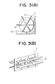
- Fig. 3(A) is a cross-sectional view of a driven roller of a second embodiment of the invention, with three rectangular vanes, each formed into one vane from two separate pieces and slidably received in a rectangular slot in the driven roller;
- Fig. 3(B) is a perspective view of the rectangular vanes of the embodiment of Fig. 3(A);
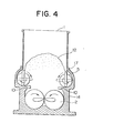
- Fig. 4 is a schematic transverse cross-sectional view of a third embodiment of the invention, showing two propelling devices; and
- Fig. 5 is a schematic perspective view showing the relationship between a housing, a guide member, and a driven roller having a rectangular vane slidable in a rectangular slot formed therein.
- Referring to the drawings, Figures 1 and 2 show a screw conveyor including a
housing 14, a pair ofscrews 2, anoutlet 4, and a hopper 1. A propelling device is provided above the screws and adjacent a wall of thehousing 14, and comprises a drivenroller 5 having arectangular vane 7 mounted therein, and aguide member 10. The hopper 1 is mounted on thehousing 14. - The
rectangular vane 7 has a greater width than the diameter of theroller 5, and it is received slidably in arectangular slot 6 in the roller. - In Fig. 2, the driven
roller 5 is partly broken away to show therectangular vane 7 received within therectangular slot 6, and a dotted line shows the periphery of the driven roller. A plurality of longitudinal grooves on theroller 5 helps the roller to frictionally engage the plastic material. - The driven
roller 5 is disposed perpendicularly to the axes of thescrews 2, and itsshaft 8 is rotatably supported by bearings 9 mounted on the upper portion of thehousing 14. The roller is rotated by a drive shaft 11, which is in turn driven by a motor (not shown). - Fig. 5 illustrates the relationship between the driven
roller 5, therectangular vane 7, theguide member 10, and thehousing 14. Theguide member 10 has an arcuate face which fits a portion of the periphery of the drivenroller 5, and two arms which extend generally horizontally from the lowest point of theguide member 10. Therectangular slot 6 extends along the length of the drivenroller 5 and diametrically across the circular cross-section thereof. The slot is preferably located so that it intersects the axis of the roller. - The
guide member 10 is mounted on the wall of thehousing 14, or it may be formed as a portion of the wall of the housing. - When the driven
roller 5 is rotated and theplastic material 12 is being delivered from the hopper 1, therectangular vane 7, moving in a direction as shown by the arrow in Fig. 1, has one of its edges pushed inwardly of theroller 5, first by the arms of theguide member 10, then by the arcuate portion thereof, so that the other edge of the vane protrudes from the periphery of the drivenroller 5 and pushes the plastic material into aninlet portion 13 of thehousing 14, thereby pushing the material onto thescrews 2. - Thus one edge (effectively the lower edge) of the rectangular vane is progressively pushed into the
roller 5 and the opposite edge (effectively the upper one) protrudes from the periphery of the roller, whereby theplastic material 12 in the hopper 1 is continuously fed onto the screws without the occurrence of the bridge phenomenon, i.e. the adherence of the material to the walls of thehousing 14. - Although this first embodiment of the invention has a rectangular vane and slot, they may take other forms, provided that the vane can move slidably in the slot and one end of the vane can protrude from the periphery of the roller.
- Figs. 3(A) and 3(B) illustrate an embodiment with three
rectangular vanes 7 and a guide member 20, the arms of which have slightly arcuate faces. Eachrectangular vane 7 is made from two stamped plates having the shapes shown in Fig. 3(B). Each plate is connected to its mating plate at A. If the vane takes the shape shown in Fig. 3(B), each vane can be slidably received in a corresponding slot. Other shapes can readily be conceived to attain the same purpose. The slightly arcuate faces of the arms of theguide member 10 are effective to smoothly and gradually push the edges of therectangular vanes 7 so as to move them into their slots. - This second embodiment of the invention pushes the plastic material more smoothly than the first embodiment, and this is brought about by the provision of a plurality of vanes.
- A third embodiment of the invention, shown in Fig. 4, has two propelling devices. Thus two driven
rollers 5 haverespective vanes 17 slidable in their slots. The rollers are again disposed at the top of thehousing 14, but this time with their axes parallel to the axes of thescrews 2. As this third embodiment has two propelling devices, one adjacent each of thescrews 2, the plastic material can be effectively pushed without it adhering to the wall of thehousing 14 or the hopper 1. - In the above described embodiments the
slot 6 extends substantially the whole length of the drivenroller 5, but alternatively two or more shorter slots could be provided at optional locations in place of theslot 6, with a corresponding number of vanes received in the slots. - Thus, by providing a vane which alternately protrudes from and retracts into a driven roller, plastic material in the hopper of the screw conveyor is effectively propelled onto the screw of the conveyor, thereby enabling the continuous feeding of plastic material, such as butter, jam, or cream, from the outlet of the screw conveyor to a subsequent processing stage.
- It is to be clearly understood that there are no particular features of the foregoing specification, or of any claims appended hereto, which are at present regarded as being essential to the performance of the present invention, and that any one or more of such features or combinations thereof may therefore be included in, added to, omitted from or deleted from any of such claims if and when amended during the prosecution of this application or in the filing or prosecution of any divisional application based thereon.
Claims (5)
Priority Applications (1)
| Application Number | Priority Date | Filing Date | Title |
|---|---|---|---|
| AT85309178T ATE77343T1 (en) | 1984-12-17 | 1985-12-17 | AUGER CONVEYOR. |
Applications Claiming Priority (2)
| Application Number | Priority Date | Filing Date | Title |
|---|---|---|---|
| JP1984191161U JPS6338775Y2 (en) | 1984-12-17 | 1984-12-17 | |
| JP191161/84 | 1984-12-17 |
Publications (2)
| Publication Number | Publication Date |
|---|---|
| EP0185541A1 true EP0185541A1 (en) | 1986-06-25 |
| EP0185541B1 EP0185541B1 (en) | 1992-06-17 |
Family
ID=16269915
Family Applications (1)
| Application Number | Title | Priority Date | Filing Date |
|---|---|---|---|
| EP85309178A Expired - Lifetime EP0185541B1 (en) | 1984-12-17 | 1985-12-17 | A screw conveyor |
Country Status (8)
| Country | Link |
|---|---|
| US (1) | US4645064A (en) |
| EP (1) | EP0185541B1 (en) |
| JP (1) | JPS6338775Y2 (en) |
| KR (1) | KR890002744Y1 (en) |
| CN (1) | CN85109680B (en) |
| AT (1) | ATE77343T1 (en) |
| DE (1) | DE3586241T2 (en) |
| ES (1) | ES8700202A1 (en) |
Cited By (6)
| Publication number | Priority date | Publication date | Assignee | Title |
|---|---|---|---|---|
| EP0298044A2 (en) * | 1987-05-29 | 1989-01-04 | Franco Annicchiarico | An improved machine for the manufacture of short cut pasta, in particular "orecchiette", "cavatelli" etc |
| EP1721728A3 (en) * | 2005-05-11 | 2007-12-19 | H & G Entsorgungssysteme GmbH | Apparatus for exerting a packing pressure on valuable products in a screw compactor or a press |
| CN102986760A (en) * | 2012-12-18 | 2013-03-27 | 苏州麦克食品机械塑胶有限公司 | Single-spiral steamed bread making machine |
| CN105613642A (en) * | 2014-11-06 | 2016-06-01 | 宁夏翔云机械科技有限公司 | Dough kneading machine |
| US9550631B2 (en) | 2009-07-24 | 2017-01-24 | Netzsch Mohnopumpen Gmbh | Feeding device having a double-disk feed having a separated drive and method for operating such a feeding device |
| CN110150345A (en) * | 2019-05-30 | 2019-08-23 | 安徽皓浩食品科技股份有限公司 | A kind of quick dough kneading device and its application method |
Families Citing this family (22)
| Publication number | Priority date | Publication date | Assignee | Title |
|---|---|---|---|---|
| JPH0524294Y2 (en) * | 1990-05-12 | 1993-06-21 | ||
| US5037008A (en) * | 1990-05-21 | 1991-08-06 | Nockleby Raymond B | Manual seed metering apparatus |
| US5519985A (en) * | 1995-03-27 | 1996-05-28 | Dyck; Rudolph H. | Machine for producing straw-filled tubes of flexible netting material |
| US7303084B2 (en) * | 2004-01-27 | 2007-12-04 | Mcphillips Kevin | Compositions, devices, and methods for use in environmental remediation |
| DE102008020411B3 (en) * | 2008-04-24 | 2009-10-29 | Netzsch-Mohnopumpen Gmbh | Feed device for screw machines |
| JP5611191B2 (en) * | 2008-04-30 | 2014-10-22 | ビーエーエスエフ ソシエタス・ヨーロピアBasf Se | Method for producing water-absorbing polymer particles |
| KR101240768B1 (en) * | 2009-10-30 | 2013-03-07 | 배경록 | The Use of Active Microbial Pellets using the Fermentation Broth made of Effective Micro-organisms and Native Micro-organisms |
| CN101966900B (en) * | 2010-11-01 | 2012-07-04 | 广州迪森热能技术股份有限公司 | Biomass silo adaptive to different pileup angles |
| CN102963633B (en) * | 2012-11-19 | 2014-05-07 | 中冶北方(大连)工程技术有限公司 | Paper sludge transfer and storage silo |
| US20150375467A1 (en) * | 2013-02-01 | 2015-12-31 | Ruf Maschinenbau Gmbh & Co Kg | Feeding device for feeding lumpy material into a briquetting press |
| CN103404550A (en) * | 2013-03-05 | 2013-11-27 | 江南大学 | Flour conveying device applied to cartoon food machinery |
| CN103814974A (en) * | 2014-02-10 | 2014-05-28 | 阳政精机(无锡)有限公司 | Device and method for forming stuffing wrappers and enabling stuffing wrappers to cover dough automatically |
| CN104003119A (en) * | 2014-06-06 | 2014-08-27 | 确成硅化学股份有限公司 | Auger conveyor |
| US9635865B1 (en) * | 2015-05-18 | 2017-05-02 | Norman Schmidt | Dough feeder |
| CN106429353A (en) * | 2016-11-28 | 2017-02-22 | 无锡市麦杰机械工程有限公司 | Stagger spiral conveying mechanism |
| CN106429352A (en) * | 2016-11-28 | 2017-02-22 | 无锡市麦杰机械工程有限公司 | Corner stirring type spiral conveying mechanism |
| CN109051382A (en) * | 2018-09-30 | 2018-12-21 | 郑州运达造纸设备有限公司 | A kind of stalk pulping raw material conveyer |
| CN109720890B (en) * | 2018-12-26 | 2020-09-04 | 北京化工大学 | A continuous feed arrangement of multistage spiral for granule material |
| JP6956145B2 (en) * | 2019-06-19 | 2021-10-27 | レオン自動機株式会社 | Food storage equipment for food processing equipment |
| KR102461163B1 (en) | 2020-08-11 | 2022-11-02 | 주식회사 포스코 | Screw conveyor |
| CN112889861A (en) * | 2021-01-27 | 2021-06-04 | 合肥膳之纤生物科技有限公司 | Plant high-fiber noodle batching system |
| CN113650346B (en) * | 2021-10-14 | 2021-12-10 | 南通众德机械制造有限公司 | Metal cutting bits compressor |
Citations (5)
| Publication number | Priority date | Publication date | Assignee | Title |
|---|---|---|---|---|
| US1481304A (en) * | 1920-12-24 | 1924-01-22 | Sharp Albert | Butter cutting and printing machine |
| DE722761C (en) * | 1939-05-31 | 1942-07-20 | Otto Schoebbel | Dough dividing machine |
| GB1282959A (en) * | 1969-09-11 | 1972-07-26 | Ricciardi Ronald J | Bin discharger |
| US4167237A (en) * | 1976-11-27 | 1979-09-11 | Torahiko Hayashi | Pressure feeder including pusher assemblies |
| EP0069929A2 (en) * | 1981-07-13 | 1983-01-19 | Par-Way Manufacturing Co. | Apparatus for uniformly distributing a powdered or granular food product |
Family Cites Families (2)
| Publication number | Priority date | Publication date | Assignee | Title |
|---|---|---|---|---|
| US1828624A (en) * | 1929-12-16 | 1931-10-20 | Continental Can Co | Feeding and timing mechanism for containers |
| US2579527A (en) * | 1948-07-23 | 1951-12-25 | Rock Island Millwork Company | Method and means for loading dry granular mixtures |
-
1984
- 1984-12-17 JP JP1984191161U patent/JPS6338775Y2/ja not_active Expired
-
1985
- 1985-12-16 CN CN85109680A patent/CN85109680B/en not_active Expired
- 1985-12-16 KR KR2019890003335U patent/KR890002744Y1/en not_active Application Discontinuation
- 1985-12-16 US US06/809,581 patent/US4645064A/en not_active Expired - Lifetime
- 1985-12-17 AT AT85309178T patent/ATE77343T1/en not_active IP Right Cessation
- 1985-12-17 EP EP85309178A patent/EP0185541B1/en not_active Expired - Lifetime
- 1985-12-17 ES ES85550028A patent/ES8700202A1/en not_active Expired
- 1985-12-17 DE DE8585309178T patent/DE3586241T2/en not_active Expired - Lifetime
Patent Citations (5)
| Publication number | Priority date | Publication date | Assignee | Title |
|---|---|---|---|---|
| US1481304A (en) * | 1920-12-24 | 1924-01-22 | Sharp Albert | Butter cutting and printing machine |
| DE722761C (en) * | 1939-05-31 | 1942-07-20 | Otto Schoebbel | Dough dividing machine |
| GB1282959A (en) * | 1969-09-11 | 1972-07-26 | Ricciardi Ronald J | Bin discharger |
| US4167237A (en) * | 1976-11-27 | 1979-09-11 | Torahiko Hayashi | Pressure feeder including pusher assemblies |
| EP0069929A2 (en) * | 1981-07-13 | 1983-01-19 | Par-Way Manufacturing Co. | Apparatus for uniformly distributing a powdered or granular food product |
Cited By (8)
| Publication number | Priority date | Publication date | Assignee | Title |
|---|---|---|---|---|
| EP0298044A2 (en) * | 1987-05-29 | 1989-01-04 | Franco Annicchiarico | An improved machine for the manufacture of short cut pasta, in particular "orecchiette", "cavatelli" etc |
| EP0298044A3 (en) * | 1987-05-29 | 1990-05-02 | Franco Annicchiarico | An improved machine for the manufacture of short cut pasta, in particular "orecchiette", "cavatelli" etc |
| EP1721728A3 (en) * | 2005-05-11 | 2007-12-19 | H & G Entsorgungssysteme GmbH | Apparatus for exerting a packing pressure on valuable products in a screw compactor or a press |
| US9550631B2 (en) | 2009-07-24 | 2017-01-24 | Netzsch Mohnopumpen Gmbh | Feeding device having a double-disk feed having a separated drive and method for operating such a feeding device |
| US9758312B2 (en) | 2009-07-24 | 2017-09-12 | Netzsch Pumpen & Systeme Gmbh | Feeding device having a double-disk feed having a separated drive and method for operating such a feeding device |
| CN102986760A (en) * | 2012-12-18 | 2013-03-27 | 苏州麦克食品机械塑胶有限公司 | Single-spiral steamed bread making machine |
| CN105613642A (en) * | 2014-11-06 | 2016-06-01 | 宁夏翔云机械科技有限公司 | Dough kneading machine |
| CN110150345A (en) * | 2019-05-30 | 2019-08-23 | 安徽皓浩食品科技股份有限公司 | A kind of quick dough kneading device and its application method |
Also Published As
| Publication number | Publication date |
|---|---|
| JPS61105486U (en) | 1986-07-04 |
| US4645064A (en) | 1987-02-24 |
| ES8700202A1 (en) | 1986-10-16 |
| CN85109680A (en) | 1986-08-20 |
| ATE77343T1 (en) | 1992-07-15 |
| KR890002744Y1 (en) | 1989-04-29 |
| CN85109680B (en) | 1988-03-30 |
| JPS6338775Y2 (en) | 1988-10-12 |
| EP0185541B1 (en) | 1992-06-17 |
| DE3586241D1 (en) | 1992-07-23 |
| ES550028A0 (en) | 1986-10-16 |
| DE3586241T2 (en) | 1992-12-10 |
Similar Documents
| Publication | Publication Date | Title |
|---|---|---|
| EP0185541B1 (en) | A screw conveyor | |
| KR900000225B1 (en) | Coin dispensing apparatus | |
| KR100779873B1 (en) | An apparatus for extruding food material and an apparatus for manufacturing the same | |
| KR100984495B1 (en) | Bulk material pump feeder | |
| EP0596612A2 (en) | Coin dispensing apparatus | |
| JPH0114847B2 (en) | ||
| EP0288655A1 (en) | Equipment for portioning out pieces of a doughy product | |
| KR890002345B1 (en) | Apparatus for quantitatively food material | |
| EP0090640A1 (en) | Quantity-metering depositor for flowable media | |
| EP0280518B1 (en) | An apparatus for quantitatively extruding food material | |
| US5370519A (en) | Apparatus for cutting and dispensing cap lining material | |
| US2629341A (en) | Dividing wheel having movable blades for pinching off portions of relatively advancing ribbon of dough or the like | |
| EP1117608B1 (en) | Stripping mechanism for a delivery fly assembly | |
| EP0457495B1 (en) | Dough-discharging apparatus | |
| CN111137697B (en) | A separating mechanism for separating lollipop | |
| EP0573944A1 (en) | Wrapping material feed and cutting device for product wrapping machines | |
| JPH0416970Y2 (en) | ||
| JPH0730585Y2 (en) | Parts separation device for continuous parts conveyance path | |
| JP3218977B2 (en) | Rotary drilling machine | |
| RU2020825C1 (en) | Molding device for half-finished confectionery products | |
| RU1788878C (en) | Device for batching viscous plastic products | |
| JPH0729695B2 (en) | Ejector for silo | |
| KR0177595B1 (en) | A sheet feed apparatus | |
| SU850385A1 (en) | Worm-screw press | |
| JPS6121688B2 (en) |
Legal Events
| Date | Code | Title | Description |
|---|---|---|---|
| PUAI | Public reference made under article 153(3) epc to a published international application that has entered the european phase |
Free format text: ORIGINAL CODE: 0009012 |
|
| AK | Designated contracting states |
Kind code of ref document: A1 Designated state(s): AT BE CH DE FR GB IT LI NL SE |
|
| 17P | Request for examination filed |
Effective date: 19861030 |
|
| 17Q | First examination report despatched |
Effective date: 19870831 |
|
| GRAA | (expected) grant |
Free format text: ORIGINAL CODE: 0009210 |
|
| ITF | It: translation for a ep patent filed |
Owner name: SOCIETA' ITALIANA BREVETTI S.P.A. |
|
| AK | Designated contracting states |
Kind code of ref document: B1 Designated state(s): AT BE CH DE FR GB IT LI NL SE |
|
| REF | Corresponds to: |
Ref document number: 77343 Country of ref document: AT Date of ref document: 19920715 Kind code of ref document: T |
|
| REF | Corresponds to: |
Ref document number: 3586241 Country of ref document: DE Date of ref document: 19920723 |
|
| ET | Fr: translation filed | ||
| PLBE | No opposition filed within time limit |
Free format text: ORIGINAL CODE: 0009261 |
|
| STAA | Information on the status of an ep patent application or granted ep patent |
Free format text: STATUS: NO OPPOSITION FILED WITHIN TIME LIMIT |
|
| 26N | No opposition filed | ||
| EAL | Se: european patent in force in sweden |
Ref document number: 85309178.3 |
|
| REG | Reference to a national code |
Ref country code: GB Ref legal event code: IF02 |
|
| PGFP | Annual fee paid to national office [announced via postgrant information from national office to epo] |
Ref country code: NL Payment date: 20041205 Year of fee payment: 20 |
|
| PGFP | Annual fee paid to national office [announced via postgrant information from national office to epo] |
Ref country code: SE Payment date: 20041206 Year of fee payment: 20 |
|
| PGFP | Annual fee paid to national office [announced via postgrant information from national office to epo] |
Ref country code: FR Payment date: 20041208 Year of fee payment: 20 |
|
| PGFP | Annual fee paid to national office [announced via postgrant information from national office to epo] |
Ref country code: DE Payment date: 20041209 Year of fee payment: 20 |
|
| PGFP | Annual fee paid to national office [announced via postgrant information from national office to epo] |
Ref country code: AT Payment date: 20041213 Year of fee payment: 20 |
|
| PGFP | Annual fee paid to national office [announced via postgrant information from national office to epo] |
Ref country code: GB Payment date: 20041215 Year of fee payment: 20 Ref country code: CH Payment date: 20041215 Year of fee payment: 20 |
|
| PGFP | Annual fee paid to national office [announced via postgrant information from national office to epo] |
Ref country code: BE Payment date: 20050629 Year of fee payment: 20 |
|
| APAH | Appeal reference modified |
Free format text: ORIGINAL CODE: EPIDOSCREFNO |
|
| PG25 | Lapsed in a contracting state [announced via postgrant information from national office to epo] |
Ref country code: GB Free format text: LAPSE BECAUSE OF EXPIRATION OF PROTECTION Effective date: 20051216 |
|
| PG25 | Lapsed in a contracting state [announced via postgrant information from national office to epo] |
Ref country code: NL Free format text: LAPSE BECAUSE OF EXPIRATION OF PROTECTION Effective date: 20051217 |
|
| REG | Reference to a national code |
Ref country code: GB Ref legal event code: PE20 |
|
| REG | Reference to a national code |
Ref country code: CH Ref legal event code: PL |
|
| NLV7 | Nl: ceased due to reaching the maximum lifetime of a patent |
Effective date: 20051227 |
|
| EUG | Se: european patent has lapsed | ||
| BE20 | Be: patent expired |
Owner name: *RHEON AUTOMATIC MACHINERY CO. LTD Effective date: 20051217 |