EP0185395A2 - Device for separating sheets - Google Patents
Device for separating sheets Download PDFInfo
- Publication number
- EP0185395A2 EP0185395A2 EP85116405A EP85116405A EP0185395A2 EP 0185395 A2 EP0185395 A2 EP 0185395A2 EP 85116405 A EP85116405 A EP 85116405A EP 85116405 A EP85116405 A EP 85116405A EP 0185395 A2 EP0185395 A2 EP 0185395A2
- Authority
- EP
- European Patent Office
- Prior art keywords
- stack
- separating
- retaining
- sheet material
- sheets
- Prior art date
- Legal status (The legal status is an assumption and is not a legal conclusion. Google has not performed a legal analysis and makes no representation as to the accuracy of the status listed.)
- Granted
Links
Images

Classifications
-
- B—PERFORMING OPERATIONS; TRANSPORTING
- B65—CONVEYING; PACKING; STORING; HANDLING THIN OR FILAMENTARY MATERIAL
- B65H—HANDLING THIN OR FILAMENTARY MATERIAL, e.g. SHEETS, WEBS, CABLES
- B65H3/00—Separating articles from piles
- B65H3/46—Supplementary devices or measures to assist separation or prevent double feed
-
- B—PERFORMING OPERATIONS; TRANSPORTING
- B65—CONVEYING; PACKING; STORING; HANDLING THIN OR FILAMENTARY MATERIAL
- B65H—HANDLING THIN OR FILAMENTARY MATERIAL, e.g. SHEETS, WEBS, CABLES
- B65H2701/00—Handled material; Storage means
- B65H2701/10—Handled articles or webs
- B65H2701/19—Specific article or web
- B65H2701/1912—Banknotes, bills and cheques or the like
Definitions
- the invention relates to a device for separating flat sheet material, for example receipts, banknotes or the like, the sheet material being transported in the form of a stack via a stack transport system into a separating device consisting essentially of a take-off device, a stacking table and a retaining device Sheet by sheet passes through a separation gap formed between the withdrawal and retention device and set to a predetermined size, from which the withdrawal device arranged behind the separation gap is detected and fed to a further transport system.
- DE-PS 24 54 082 describes a separating device consisting of a separating roller, a retaining roller, a retaining device, a stacking table and a feed roller.
- the sheets on the stacking table are conveyed through the feed roller to the separation roller through a separation gap formed between the separation roller and the retaining device.
- the separating roller is designed as a suction roller and detects the leading edges of the sheets to be separated in order to transfer them one after the other to a further transport system.
- a retaining roller is provided opposite the separating roller, which is also designed as a suction roller, rotates in the opposite direction as the separating roller and ensures that the sheets not in contact with the suction roller are pushed back into the stacking area.
- the retaining device against which the sheet leading edges of the stack rest and which, together with the singling roll, forms the singling gap, ensures that only a limited number of sheets are fed to the singling roll.
- the Retention device thus causes a kind of pre-separation.
- Separating devices have also become known in which the feed of the individual sheets is carried out through the separating gap to the separating roller with the aid of a so-called air guide plate (see DE-OS 28 14 306).
- separating devices of the type described are used in high-speed sorting systems, it is of great importance for the economic efficiency of the system that the separating device achieves a high throughput with high separating reliability. This means that not only a rapid separation of the stack of sheets, but also a rapid replenishment of the stack of sheets must be ensured in the separation device. After the last sheet has been separated in the separating device, a new stack of sheets should be provided on the stacking table as quickly as possible. So that the actual separation can begin quickly after the transport of a new stack of sheets into the separation device, it is advantageous if some leaves have already passed the separation gap and are advanced to the separation roller.
- the object of the invention is therefore to propose a method for separating flat sheet material, with which a substantially higher throughput of sheet material stacks can be achieved with the same separation security.
- the object is achieved by the features specified in the characterizing part of the main claim.
- An essential feature of the invention is to reduce the separating gap in each case before a stack is fed into the separating device and to reset it to the originally specified width immediately before starting the separation.
- the retaining device Before a stack is fed in, for example, the retaining device itself is moved in the direction of the separating roller. Several sheets can still wedge in the separation gap that is reduced in this way. However, this is irrelevant since the separating gap is reset to the original width immediately before the beginning of separating, whereby any wedging that may have occurred is canceled out again.
- An advantage of the solution according to the invention is that the throughput of stacks of sheet material in the separating device can be increased considerably with a constant separation security with a structurally simple measure. As soon as the last sheet material has been separated in the separating device, a new stack of sheet material can be conveyed into the device at high speed without wedging of sheets in the separating gap would interfere with the separating process.
- the restraint device in addition to reducing the width of the separating gap, the surface which forms the front edge of the stack che of the restraint temporarily changed before each entry of a stack into the separating device.
- the restraint device has a movable part in addition to a stationary part. This can be controlled in such a way that, based on the stationary part of the retaining device, a protruding run-up surface is created against which the front edge of the stack of sheet material being transported abuts. If this run-up surface is pulled back into the stationary part of the retaining device immediately before the start of the separation, a free gap remains between the front edge of the stack and the stationary part, which enables the stack to be advanced without friction on the retention device.
- the movable part of the retaining device can also be toothed or roughened on the side that comes into contact with the front edge of the stack.
- a serrated surface prevents individual sheets from sliding with their leading edges along the retaining device in front of the leading edges of other sheets and thus disrupting the separation process.
- the movable element is removed from the leading edge of the sheet, so that the stack feed required for separation can be carried out undisturbed.
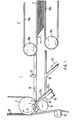
- separating device 1 shows, in an exemplary embodiment, a separating device 1, as is used, for example, in high-speed sorting machines.
- a stack of sheet material 3 is transported to the separating device with a stack transport system 2 when the last sheet of the previous stack is separated.
- the separating device essentially consists of a pressure plate 14, a feed device 16, a separating roller 5, a retaining roller 8 and egg ner retaining device 10, hereinafter referred to as a retaining element.
- the pressure plate 14 takes over the stack of sheets 3 transported by the stack transport system 2, consisting of the belts 19a, 19b and the transport rollers 18a, 18b, and conveys them to the feed device 16, which is designed, for example, as an air guide plate.
- the feed device 16 which is designed, for example, as an air guide plate.
- the air baffle plate 16 in which blown air bores that can be supplied with blown air are arranged in such a way that they give the top sheet material of the stack a movement component in the singling direction, the sheets are transported sequentially to the singling roll 5.
- suction openings 7 in the separating roller 5 By means of suction openings 7 in the separating roller 5, the respective leading edges of the sheet are grasped and transferred by rotation in the direction of the arrow 6 into the subsequent transport system, consisting of the belts 20 and the transport roller 21.
- the leading edges of the sheets lie on the retaining element 10, a gap 11 of a predetermined size being set between the retaining element and the singling roller 5 or air guide plate 16, so that only the upper sheets directly abutting the air guide plate 16 are conveyed to the singling roller 5 as far as possible.
- the retaining roller 8 is provided, which rotates in the direction of arrow 9 against the separating direction and has suction openings distributed over its circumference.
- the sheets which have already been transported through the separating gap 11 by means of the air guide plate 16 are retained by the retaining roller 8 rotating counter to the separating direction, so that the separating roller 5 only separates the uppermost sheet material of the stack.
- the stack transport system 2 can be designed so that its lower belts 19b run somewhat slower than the upper belts 19a. As a result, the sheets lying at the bottom of the stack can be displaced relative to one another above them, so that a wedge-shaped stack leading edge pointing in the transport direction 4 results. This measure serves to preposition the sheet leading edges to the shape required for the separation.
- the retaining element 10 is movably arranged, as shown in FIG. 2.
- a control device 13 connected to the retaining element 10, with which the element can be moved in accordance with the arrows 12a, 12b shown.
- a motor which can be switched in the direction of rotation and which, equipped with a suitable gear, performs the desired translational movement can be used, for example, to move the retaining element.
- the transport system 2 is activated for feeding a further stack and on the other hand the retaining element 10 in the direction of the arrow 12a in the dashed lines represented working position.
- the separation process is started.
- the retaining element 10 is moved into the rest position in the direction of the arrow 12b, thereby ensuring that any wedging of sheets in the separating gap that may have occurred is eliminated.
- the stacking table 14 is successively moved in the direction of the arrow 15 (see FIG. 1) by a drive, not shown in FIG. 1, so that the stack of sheets is always in contact with the air guide plate 16. In this phase, wedging in the separating gap is unlikely for sheets of conventional quality, since the gap width is now set so that the sheets conveyed by the air guide plate can safely pass through the separating gap 11 without clamping.
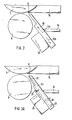
- FIG. 3a and 3b show a further embodiment of the invention, in addition to a stationary retaining element 22, a second, movably attached ordered element 23 is provided.
- Fig. 3a shows this element in the rest and Fig. 3b in the working position.
- the second movably arranged element 23 can by a suitable control unit 24, such as. B. an electromagnet can be moved via a pivot point 25 against the force of a spring 26 in the direction of arrow 28. The element 23 is then in the working position shown in FIG. 3b. If the excitation of the electromagnet is switched off, the element 23 moves due to the spring force into the rest position shown in FIG. 3a.
- the actual, stationary retaining element 22 is preferably designed in a rake-like manner, with a plurality of movable elements 23 coupled to one another being provided in a comb-like manner in several gaps of the rake.
- the reduction in width of the separating gap can be set in many stages almost arbitrarily until the gap is completely closed.
- the separating gap can thus be adapted to the respective requirements of the sheet material, such as sheet thickness, paper quality, etc.
- the element 23 is designed such that it protrudes from the stationary retaining element 22 in the working position in the direction of the stacking edge to be expected.
- the protruding surface of the element 23, which forms the front edge of the stack of sheet material, is parallel to the corresponding surface of the stationary retaining element 22. If the movable element 23 is moved into the rest position after the supply of a stack of sheet material, the front edge of the stack of sheet material is parallel with a small distance to the surface of the stationary retaining element 22.
- the gap thus formed between the front edge of the stack and the retaining element 22 has the advantage that the leading edges of the individual sheets can be conveyed to the air guide plate 16 without friction on the contact surface of the retaining element 22 by gradually raising the pressure plate 14.
- This disturbance can also occur in the case of particularly lobed, heavily worn sheets when the sheet material stack that is being transported at high speed hits the retaining element with its front edge.
- the movable element 23 is provided with a special surface on the side interacting with the front edge of the stack.
- the element 23 can be provided with a toothing 27 consisting of several steps, which is designed such that the step depths parallel and the step heights, which meet the leading edges of the blades, are perpendicular to the air guide plate 16 .
- the toothing 27 can have a different height and a different number of steps, depending on the sheet thickness and paper quality of the sheets to be separated. 4, the entire surface acting on the front edge of the stack is toothed.
- the toothing can also be provided only in the area of the separating gap or only in the central area of the element 23.
Abstract
Description
Die Erfindung betrifft eine Vorrichtung zum Vereinzeln von flachem Blattgut, beispielsweise von Belegen, Banknoten oder dergleichen, wobei das Blattgut in Form eines Stapels über ein Stapel-Transportsystem in eine im wesentlichen aus einer Abzugseinrichtung, einem Stapeltisch und einer Rückhalteeinrichtung bestehende Vereinzelungsvorrichtung transportiert, in dieser Blatt für Blatt einen zwischen Abzugs- und Rückhalteeinrichtung gebildeten und auf eine vorgegebene Größe eingestellten Vereinzelungsspalt passiert, von der hinter dem Vereinzelungsspalt angeordneten Abzugseinrichtung erfaßt und einem weiterführenden Transportsystem zugeführt wird.The invention relates to a device for separating flat sheet material, for example receipts, banknotes or the like, the sheet material being transported in the form of a stack via a stack transport system into a separating device consisting essentially of a take-off device, a stacking table and a retaining device Sheet by sheet passes through a separation gap formed between the withdrawal and retention device and set to a predetermined size, from which the withdrawal device arranged behind the separation gap is detected and fed to a further transport system.
Verfahren bzw. Vorrichtungen zum Vereinzeln von flachem Blattgut sind vielfach bekannt.Methods and devices for separating flat sheet material are widely known.
Die DE-PS 24 54 082 beispielsweise beschreibt eine Vereinzelungsvorrichtung, bestehend aus einer Vereinzelungswalze, einer Rückhaltewalze, einer Rückhalteeinrichtung, einem Stapeltisch und einer Vorschubwalze. Durch die Vorschubwalze werden die auf dem Stapeltisch befindlichen Blätter durch einen zwischen Vereinzelungswalze und Rückhalteeinrichtung gebildeten Vereinzelungsspalt zur Vereinzelungswalze befördert. Die Vereinzelungswalze ist als Saugwalze ausgebildet und erfaßt die Vorderkanten der zu vereinzelnden Blätter, um diese nacheinander einem weiterführenden Transportsystem zu übergeben. Um Doppelabzüge zu verhindern, ist gegenüber der Vereinzelungswalze eine Rückhaltewalze vorgesehen, die ebenfalls als Saugwalze ausgebildet, sich im umgekehrten Sinne wie die Vereinzelungswalze dreht und dafür sorgt, daß die nicht an der Saugwalze anliegenden Blätter in den Stapelbereich zurückgeschoben werden. Die Rückhalteeinrichtung, an der die Blattvorderkanten des Stapels anliegen und die zusammen mit der Vereinzelungswalze den Vereinzelungsspalt bildet, sorgt dafür, daß nur eine begrenzte Zahl von Blättern zur Vereinzelungswalze vorgeschoben wird. Die Rückhalteeinrichtung bewirkt somit eine Art Vorvereinzelung.DE-PS 24 54 082, for example, describes a separating device consisting of a separating roller, a retaining roller, a retaining device, a stacking table and a feed roller. The sheets on the stacking table are conveyed through the feed roller to the separation roller through a separation gap formed between the separation roller and the retaining device. The separating roller is designed as a suction roller and detects the leading edges of the sheets to be separated in order to transfer them one after the other to a further transport system. In order to prevent double deductions, a retaining roller is provided opposite the separating roller, which is also designed as a suction roller, rotates in the opposite direction as the separating roller and ensures that the sheets not in contact with the suction roller are pushed back into the stacking area. The retaining device, against which the sheet leading edges of the stack rest and which, together with the singling roll, forms the singling gap, ensures that only a limited number of sheets are fed to the singling roll. The Retention device thus causes a kind of pre-separation.
Es.sind auch Vereinzelungsvorrichtungen bekannt geworden, bei denen der Vorschub der einzelnen Blätter durch den Vereinzelungsspalt zur Vereinzelungswalze mit Hilfe einer sogenannten Luftleitplatte vorgenommen wird (siehe dazu DE-OS 28 14 306).Separating devices have also become known in which the feed of the individual sheets is carried out through the separating gap to the separating roller with the aid of a so-called air guide plate (see DE-OS 28 14 306).
Werden Vereinzelungsvorrichtungen der beschriebenen Art in Hochgeschwindigkeits-Sortieranlagen eingesetzt, ist es für die Wirtschaftlichkeit der Anlage von großer Bedeutung, daß die Vereinzelungsvorrichtung bei hoher Vereinzelungssicherheit einen hohen Durchsatz erzielt. Das bedeutet, daß nicht nur für eine schnelle Vereinzelung des Blattgutstapels, sondern auch für einen schnellen Nachschub von Blattgutstapeln in die Vereinzelungsvorrichtung gesorgt werden muß. Nach der Vereinzelung des letzten Blattes in der Vereinzelungsvorrichtung sollte so schnell wie möglich ein neuer Blattgutstapel auf dem Stapeltisch bereitgestellt werden. Damit nach dem Antransport eines neuen Blattgutstapels in die Vereinzelungsvorrichtung, die eigentliche Vereinzelung schnell beginnen kann, ist es vorteilhaft, wenn bereits einige Blätter den Vereinzelungsspalt passiert haben und bis zur Vereinzelungswalze vorgeschoben sind.If separating devices of the type described are used in high-speed sorting systems, it is of great importance for the economic efficiency of the system that the separating device achieves a high throughput with high separating reliability. This means that not only a rapid separation of the stack of sheets, but also a rapid replenishment of the stack of sheets must be ensured in the separation device. After the last sheet has been separated in the separating device, a new stack of sheets should be provided on the stacking table as quickly as possible. So that the actual separation can begin quickly after the transport of a new stack of sheets into the separation device, it is advantageous if some leaves have already passed the separation gap and are advanced to the separation roller.
Es hat sich nun gezeigt, daß die Gefahr, daß sich Blätter im Vereinzelungsspalt verkeilen, umso größer ist, je schneller die Stapel in die Vereinzelungsvorrichtung transportiert werden. Die Folge davon ist, daß der Vereinzelungsvorgang unterbrochen wird. Mit schnellerem Antransport der Stapel allein kann somit der Durchsatz der bekannten Vereinzelungsvorrichtung nicht entscheidend verbessert werden.It has now been shown that the faster the stacks are transported into the separating device, the greater the risk that sheets will wedge in the separating gap. The result of this is that the separation process is interrupted. With faster transport of the stacks alone, the throughput of the known separating device cannot be decisively improved.
Die Aufgabe der Erfindung ist es daher, ein Verfahren zum Vereinzeln von flachem Blattgut vorzuschlagen, mit dem bei gleichbleibender Vereinzelungssicherheit ein wesentlich höherer Durchsatz von Blattgutstapeln erzielt werden kann.The object of the invention is therefore to propose a method for separating flat sheet material, with which a substantially higher throughput of sheet material stacks can be achieved with the same separation security.
Erfindungsgemäß wird die Aufgabe durch die im Kennzeichen des Hauptanspruchs angegebenen Merkmale gelöst.According to the invention the object is achieved by the features specified in the characterizing part of the main claim.
Ein wesentliches Merkmal der Erfindung besteht darin, den Vereinzelungsspalt jeweils vor der Zufuhr eines Stapels in die Vereinzelungsvorrichtung zu verkleinern und unmittelbar vor Beginn der Vereinzelung auf die ursprünglich vorgegebene Weite zurückzustellen. Vor der Zufuhr eines Stapels wird dazu beispielsweise die Rückhalteeinrichtung selbst in Richtung Vereinzelerwalze bewegt. Im so verkleinerten Vereinzelungsspalt können sich zwar immer noch mehrere Blätter verkeilen. Dies ist jedoch ohne Bedeutung, da der Vereinzelungsspalt unmittelbar vor Vereinzelungsbeginn wieder auf die ursprüngliche Weite eingestellt wird, wodurch eine gegebenenfalls eingetretene Verkeilung wieder aufgehoben wird.An essential feature of the invention is to reduce the separating gap in each case before a stack is fed into the separating device and to reset it to the originally specified width immediately before starting the separation. Before a stack is fed in, for example, the retaining device itself is moved in the direction of the separating roller. Several sheets can still wedge in the separation gap that is reduced in this way. However, this is irrelevant since the separating gap is reset to the original width immediately before the beginning of separating, whereby any wedging that may have occurred is canceled out again.
Ein Vorteil der erfindungsgemäßen Lösung besteht darin, daß mit einer konstruktiv einfachen Maßnahme der Durchsatz von Blattgutstapeln in der Vereinzelungsvorrichtung bei gleichbleibender Vereinzelungssicherheit erheblich gesteigert werden kann. Sobald das letzte Blattgut in der Vereinzelungsvorrichtung vereinzelt wurde, kann ein neuer Blattgutstapel mit hoher Geschwindigkeit in die Vorrichtung befördert werden, ohne daß eine Verkeilung von Blättern im Vereinzelungsspalt den Vereinzelungsvorgang stören würde.An advantage of the solution according to the invention is that the throughput of stacks of sheet material in the separating device can be increased considerably with a constant separation security with a structurally simple measure. As soon as the last sheet material has been separated in the separating device, a new stack of sheet material can be conveyed into the device at high speed without wedging of sheets in the separating gap would interfere with the separating process.
Gemäß einer vorteilhaften Weiterbildung der Erfindung wird zusätzlich zur Verkleinerung der Weite des Vereinzelungsspaltes die die Stapelvorderkante formende Oberfläche der Rückhalteeinrichtung jeweils vor Einlauf eines Stapels in die Vereinzelungsvorrichtung vorübergehend geändert. Dazu weist die Rückhalteeinrichtung neben einem stationären Teil ein bewegliches Teil auf. Dieses ist derart ansteuerbar, daß eine, bezogen auf den stationären Teil der Rückhalteeinrichtung, vorstehende Auflauffläche entsteht, an die die Vorderkante des antransportierten Blattgutstapels anstößt. Wird diese Auflauffläche unmitJ' telbar vor Vereinzelungsbeginn in das stationäre Teil der Rückhalteeinrichtung zurückgezogen, verbleibt zwischen Stapelvorderkante und stationären Teil ein freier Spalt, der den bei der Vereinzelung notwendigen Vorschub des Stapels ohne Reibung an der Rückhalteeinrichtung ermöglicht.According to an advantageous development of the invention, in addition to reducing the width of the separating gap, the surface which forms the front edge of the stack che of the restraint temporarily changed before each entry of a stack into the separating device. For this purpose, the restraint device has a movable part in addition to a stationary part. This can be controlled in such a way that, based on the stationary part of the retaining device, a protruding run-up surface is created against which the front edge of the stack of sheet material being transported abuts. If this run-up surface is pulled back into the stationary part of the retaining device immediately before the start of the separation, a free gap remains between the front edge of the stack and the stationary part, which enables the stack to be advanced without friction on the retention device.
Das bewegliche Teil der Rückhalteeinrichtung kann auch auf der mit der Vorderkante des Stapels in Berührung kommenden Seite verzahnt oder aufgerauht ausgebildet werden.The movable part of the retaining device can also be toothed or roughened on the side that comes into contact with the front edge of the stack.
Der Vorteil des vorübergehenden Einbringens eines separaten, beweglichen Elements mit entsprechend ausgebildeter Oberfläche besteht darin, daß auf die Vorderkante des schnell antransportierten Stapels Einfluß genommen werden kann, daß aber die Vereinzelung selbst durch diese Maßnahme nicht gestört wird. Eine gezahnte Oberfläche verhindert beispielsweise, daß sich einzelne Blätter mit ihren Vorderkanten an der Rückhalteeinrichtung entlang vor die Vorderkanten anderer Blätter schieben und so den Vereinzelungsvorgang stören. Vor Vereinzelungsbeginn wird das bewegliche Element von der Blattvorderkante entfernt, so daß der zur Vereinzelung notwendige Vorschub des Stapels ungestört vorgenommen werden kann.The advantage of temporarily introducing a separate, movable element with a suitably designed surface is that it is possible to influence the front edge of the stack that is being transported quickly, but that the separation itself is not disturbed by this measure. A serrated surface, for example, prevents individual sheets from sliding with their leading edges along the retaining device in front of the leading edges of other sheets and thus disrupting the separation process. Before the start of separation, the movable element is removed from the leading edge of the sheet, so that the stack feed required for separation can be carried out undisturbed.
Weitere Vorteile sowie Weiterbildungen der Erfindung ergeben sich aus den Unteransprüchen sowie aus der nachfolgenden Beschreibung von Ausführungsbeispielen der Erfindung anhand der beigefügten Zeichnungen.Further advantages and developments of the invention result from the subclaims and from the following description of exemplary embodiments of the invention with the accompanying drawings.
Darin zeigen:
- Fig. 1 eine Seitenansicht der Vereinzelungsvorrichtung und eines Blattgutstapel-Transportsystems,
- Fig. 2 einen Ausschnitt der Vereinzelungsvorrichtung in Seitenansicht mit einer beweglichen Rückhalteeinrichtung in der Arbeits- und Ruheposition,
- Fig. 3a einen Ausschnitt der Vereinzelungsvorrichtung in Seitenansicht mit einem stationären Teil der Rückhalteeinrichtung und einem beweglichen Teil der Rückhalteeinrichtung, wobei sich das bewegliche Teil in der Ruheposition befindet,
- Fig. 3b wie Fig. 3a, wobei sich das bewegliche Teil der Rückhalteeinrichtung in der Arbeitsposition befindet,
- Fig. 4 eine Weiterbildung der Fig. 3b, wobei die Oberfläche des beweglichen Teils der Rückhalteeinrichtung aufgerauht ist.
- 1 is a side view of the separating device and a sheet material stack transport system,
- 2 shows a detail of the separating device in side view with a movable retaining device in the working and rest position,
- 3a shows a detail of the separating device in a side view with a stationary part of the retaining device and a movable part of the retaining device, the movable part being in the rest position,
- 3b like Fig. 3a, wherein the movable part of the restraint is in the working position,
- Fig. 4 is a development of Fig. 3b, wherein the surface of the movable part of the retaining device is roughened.
Die Fig. 1 zeigt in einer beispielhaften Ausführungsform eine Vereinzelungsvorrichtung 1, wie sie beispielsweise in Hochgeschwindigkeits-Sortierautomaten verwendet wird. Mit einem Stapeltransportsystem 2 wird ein Blattgutstapel 3 jeweils dann zur Vereinzelungsvorrichtung transportiert, wenn das letzte Blatt des vorhergehenden Stapels vereinzelt ist.1 shows, in an exemplary embodiment, a
Die Vereinzelungsvorrichtung besteht im wesentlichen aus einer Andruckplatte 14, einer Vorschubeinrichtung 16, einer Vereinzelungswalze 5, einer Rückhaltewalze 8 und einer Rückhalteeinrichtung 10, im folgenden als Rückhalteelement bezeichnet.The separating device essentially consists of a
Die Andruckplatte 14 übernimmt die vom Stapel-Transportsystem 2, bestehend aus den Riemen 19a, 19b und den Transportrollen 18a, 18b, antransportierten Blattgutstapel 3 und befördert sie zur Vorschubeinrichtung 16, die beispielsweise als Luftleitplatte ausgebildet ist. Mit Hilfe der Luftleitplatte 16, in der mit Blasluft versorgbare Blasluftbohrungen so angeordnet sind, daß sie dem jeweils obersten Blattgut des Stapels eine Bewegungskomponente in Vereinzelungsrichtung verleihen, werden die Blätter sequentiell zur Vereinzelungswalze 5 transportiert. Mittels Saugöffnungen 7 in der Vereinzelungswalze 5 werden die jeweiligen Blattvorderkanten erfaßt und durch Drehung in Richtung des Pfeils 6 in das nachfolgende Transportsystem, bestehend aus den Riemen 20 und der Transportrolle 21, überführt.The
Während der Vereinzelung liegen die Vorderkanten der Blätter am Rückhalteelement 10, wobei zwischen Rückhalteelement und Vereinzelungswalze 5 bzw. Luftleitplatte 16 ein Spalt 11 vorbestimmter Größe eingestellt ist, so daß möglichst immer nur die an der Luftleitplatte 16 direkt anliegenden oberen Blätter zur Vereinzelungswalze 5 befördert werden.During the singulation, the leading edges of the sheets lie on the
Gegenüber der Vereinzelungswalze 5 ist die Rückhaltewalze 8 vorgesehen, die entgegen der Vereinzelungsrichtung in Richtung des Pfeils 9 rotiert und auf ihrem Umfang verteilt Saugöffnungen aufweist. Die Blätter, die bereits durch den Vereinzelungsspalt 11 mittels der Luftleitplatte 16 transportiert worden sind, werden durch die entgegen der Vereinzelungsrichtung drehenden Rückhaltewalze 8 zurückgehalten, so daß die Vereinzelungswalze 5 jeweils nur das oberste Blattgut des Stapels vereinzelt. Bezüglich der Einzelheiten der hier nur kurz beschriebenen Vereinzelungsvorrichtung wei auf die DE-OS 28 14 306 verwiesen.Compared to the separating
Unabhängig von einer speziellen Vereinzelungsvorrichtung liegen die wesentlichen Merkmale der Erfindung in der besonderen Ausbildung und Steuerung des Rückhalteelements, was nachfolgend anhand der Fig. erläutert sei.Regardless of a special separating device, the essential features of the invention lie in the special design and control of the retaining element, which is explained below with reference to the figure.
Um einen hohen Durchsatz von Blattgutstapeln in der Vereinzelungsvorrichtung zu gewährleisten, ist es notwendig, daß möglichst schnell ein neuer zu vereinzelnder Blattstapel bereitgestellt wird, sobald das letzte Blatt des vorhergehenden Stapels die Vereinzelungsvorrichtung verlassen hat. Dies geschieht mit Hilfe des in Fig. 1 dargestellten Stapel-Transportsystems 2. Das Stapel-Transportsystem kann dabei so ausgelegt sein, daß seine unteren Riemen 19b etwas langsamer als die oberen Riemen 19a laufen. Dadurch können die unten im Stapel liegenden Blätter gegenüber den darüberliegenden zueinander verschoben werden, so daß sich eine in Transportrichtung 4 weisende keilförmige Stapelvorderkante ergibt. Diese Maßnahme dient dazu, die Blattvorderkanten auf die für die Vereinzelung notwendige Form vorzupositionieren. Wenn das antransportierte Päckchen das Stapel-Transportsystem verlassen hat, wird dessen Weiterführung bis zum Rückhalteelement 10 auf der Andruckplatte 14 gleitend allein durch die Massenträgheit des Stapels 3 bewerkstelligt.In order to ensure a high throughput of sheet material stacks in the separating device, it is necessary that a new sheet stack to be separated is provided as soon as possible as soon as the last sheet of the previous stack has left the separating device. This is done with the aid of the
Bedingt durch den schnellen Antransport des Blattgutstapels können dabei, was durchaus erwünscht ist, bereits mehrere Blätter entsprechend der eingestellten Weite des Vereinzelungsspaltes 11 bis zur Vereinzelungs- bzw. Rückhaltewalze vorstoßen. Um aber gerade beim Einlauf eines Stapels in die Vereinzelungsvorrichtung eine mögliche Verkeilung einzelner Blätter im Vereinzelungsspalt auszuschließen, ist das Rückhalteelement 10, wie in Fig. 2 gezeigt, beweglich angeordnet. Neben den bereits erwähnten Elementen der Vereinzelungsvorrichtung zeigt die Fig. 2 eine mit dem Rückhalteelement 10 verbundene Steuerungseinrichtung 13, mit der das Element entsprechend der gezeigten Pfeile 12a, 12b bewegbar ist. Zur Bewegung des Rückhalteelements kann beispielsweise ein in der Drehrichtung umschaltbarer Motor verwendet werden, der, mit einem geeigneten Getriebe ausgerüstet, die gewünschte Translationsbewegung ausführt. Sobald das letzte Blatt eines Stapels vereinzelt worden ist, was mit Hilfe einer Lichtschranke 17 (siehe Fig. 1) festgestellt werden kann, wird einerseits das Transportsystem 2 zur Zufuhr eines weiteren Stapels aktiviert und andererseits das Rückhalteelement 10 in Richtung des Pfeils 12a in die strichliert dargestellte Arbeitsposition gefahren. Sobald der Blattgutstapel mit seiner Vorderkante am Rückhalteelement auf dem Stapeltisch liegt, wird der Vereinzelungsvorgang gestartet.As a result of the rapid transport of the stack of sheet material, several sheets can advance, as is desirable, according to the set width of the
Bevor nun die Vereinzelerwalze 5 das erste Blatt vom Stapel abzieht, wird das Rückhalteelement 10 in Richtung des Pfeils 12b in die Ruheposition gefahren, womit sichergestellt wird, daß eine gegebenenfalls eingetretene Verkeilung von Blättern im Vereinzelungsspalt aufgehoben wird. Während des Vereinzelungsvorganges wird der Stapeltisch 14 sukzessive in Richtung des Pfeils 15 (siehe Fig. 1) durch einen in der Fig. 1 nicht gezeigten Antrieb bewegt, so daß der Blattgutstapel immer an der Luftleitplatte 16 anliegt. In dieser Phase ist bei Blättern üblicher Qualität eine erneute Verkeilung im Vereinzelungsspalt unwahrscheinlich, da die Spaltbreite nun so eingestellt ist, daß die von der Luftleitplatte beförderten Blätter den Vereinzelungsspalt 11 ohne Klemmung sicher passieren können.Before the separating
In den Fig. 3a und 3b ist eine weitere Ausführungsform der Erfindung gezeigt, wobei neben einem stationär angeordneten Rückhalteelement 22 ein zweites, beweglich angeordnetes Element 23 vorgesehen ist. Die Fig. 3a zeigt dieses Element in der Ruhe- und die Fig. 3b in der Arbeitsposition.3a and 3b show a further embodiment of the invention, in addition to a
Das zweite beweglich angeordnete Element 23 kann durch eine geeignete Steuereinheit 24, wie z. B. einen Elektromagneten, über einen Drehpunkt 25 gegen die Kraft einer Feder 26 in Richtung des Pfeils 28 bewegt werden. Das Element 23 befindet sich dann in der in Fig. 3b gezeigten Arbeitsposition. Wird die Anregung des Elektromagneten abgeschaltet, bewegt sich das Element 23 aufgrund der Federkraft in die in Fig. 3a gezeigte Ruheposition. Vorzugsweise ist das eigentliche, stationär angeordnete Rückhalteelement 22 rechenartig ausgebildet, wobei in mehreren Lücken des Rechens mehrere miteinander gekoppelte bewegliche Elemente 23 kammartig verzahnt vorgesehen sind.The second movably arranged
Wird die Ansteuerung des Element 23 z. B. mit Hilfe eines Schrittmotors vorgenommen, so kann die Verkleinerung der Weite des Vereinzelungsspalts in vielen Stufen nahezu beliebig bis zum vollständigen Schließen des Spalts eingestellt werden. Damit kann der Vereinzelungsspalt den jeweiligen Anforderungen des Blattgutes wie Blattdicke, Papierqualität etc. angepaßt werden.If the control of the element 23 z. B. made with the help of a stepper motor, the reduction in width of the separating gap can be set in many stages almost arbitrarily until the gap is completely closed. The separating gap can thus be adapted to the respective requirements of the sheet material, such as sheet thickness, paper quality, etc.
Die Ansteuerung des beweglichen Elements 23 und die damit verbundene Veränderung des Vereinzelungsspalts 11 in Abhängigkeit von Stapelantransport und Vereinzelung geschieht wie im Zusammenhang mit der Fig. 2 beschrieben. Darüberhinaus erlaubt jedoch die Verwendung eines zusätzlichen, beweglichen Elements auch auf die Vorderkante des Blattgutstapels während bestimmter Verfahrensabläufe zusätzlich Einfluß zu nehmen.The actuation of the
Wie man vor allem der Fig. 3b entnehmen kann, ist das Element 23 derart ausgebildet, daß es in der Arbeitsposition in Richtung auf die zu erwartende Stapelvorderkante aus dem stationären Rückhalteelement 22 herausragt. Die vorstehende und die Vorderkante des antransportierten Blattgutstapels formende Oberfläche des Elements 23 liegt dabei parallel zur entsprechenden Oberfläche des stationär angeordneten Rückhalteelements 22. Wird nach der Zufuhr eines Blattgutstapels das bewegliche Element 23 in die Ruheposition bewegt, dann liegt die Vorderkante des Blattgutstapels mit geringem Abstand parallel zur Oberfläche des stationären Rückhalteelements 22. Der so zwischen Stapelvorderkante und Rückhalteelement 22 entstandene Spalt hat den Vorteil, daß die Vorderkanten der einzelnen Blätter ohne Reibung an der Auflauffläche des Rückhalteelements 22 durch sukzessives Hochfahren der Andrückplatte 14 zur Luftleitplatte 16 befördert werden können.As can be seen above all from FIG. 3b, the
Die Erzeugung eines Spalts ist grundsätzlich auch mit dem anhand der Fig. 2 beschriebenen Rückhalteelements 10 möglich, wenn dieses zur Einstellung der Arbeitsposition um einen Drehpunkt in Richtung auf die Stapelvorderkante geschwenkt wird. Bei beiden Ausführungsformen wird vermieden, daß beispielsweise stark abgenutzte Blätter während des Hochfahrens zur Luftleitplatte am Rückhalteelement verhaken und entgegen der Vorschubrichtung abgleiten. Dies hätte zur Folge, daß die Luftleitplatte 16 dieses und auch die nachfolgenden Blätter nicht durch den Vereinzelungsspalt 11 zur Vereinzelungswalze 5 befördern könnte.The generation of a gap is fundamentally also possible with the retaining
Diese Störung kann bei besonders lappigen, stark abgenutzen Blättern auch dann schon auftreten, wenn der mit hoher Geschwindigkeit antransportierte Blattgutstapel mit seiner Vorderkante an das Rückhalteelement prallt.This disturbance can also occur in the case of particularly lobed, heavily worn sheets when the sheet material stack that is being transported at high speed hits the retaining element with its front edge.
Um dieser möglichen Störung vorzubeugen, wird das bewegliche Element 23 auf der mit der Stapelvorderkante zusammenwirkenden Seite mit einer speziellen Oberfläche versehen. Wie dazu die Fig. 4 zeigt, kann das Element 23 mit einer aus mehreren Stufen bestehende Zahnung 27 versehen werden, die so ausgelegt ist, daß jeweils die Stufentiefen parallel und die Stufenhöhen, auf die die Vorderkanten der Blätter auftreffen, senkrecht zur Luftleitplatte 16 verlaufen. Die Zahnung 27 kann je nach Blattdicke und Papierqualität der zu vereinzelnden Blätter eine unterschiedliche Höhe und eine unterschiedliche Anzahl von Stufen aufweisen. In der Fig. 4 ist die gesamte auf die Vorderkante des Stapels einwirkende Oberfläche gezahnt ausgeführt. Je nach Anforderung kann die Zahnung auch nur im Bereich des Vereinzelungsspaltes oder nur im Mittelbereich des Elements 23 vorgesehen sein. Unmittelbar vor Vereinzelungsbeginn wird das bewegliche Rückhalteelement in die Ruhelage bewegt, so daß die Zahnung auf den Vereinzelungsprozeß selbst keinen Einfluß hat.In order to prevent this possible disturbance, the
Claims (10)
Priority Applications (1)
| Application Number | Priority Date | Filing Date | Title |
|---|---|---|---|
| AT85116405T ATE43122T1 (en) | 1984-12-21 | 1985-12-20 | DEVICE FOR SEPARATING LEAF. |
Applications Claiming Priority (2)
| Application Number | Priority Date | Filing Date | Title |
|---|---|---|---|
| DE3446862 | 1984-12-21 | ||
| DE19843446862 DE3446862A1 (en) | 1984-12-21 | 1984-12-21 | DEVICE AND METHOD FOR SEPARATING LEAF |
Publications (3)
| Publication Number | Publication Date |
|---|---|
| EP0185395A2 true EP0185395A2 (en) | 1986-06-25 |
| EP0185395A3 EP0185395A3 (en) | 1987-03-18 |
| EP0185395B1 EP0185395B1 (en) | 1989-05-17 |
Family
ID=6253544
Family Applications (1)
| Application Number | Title | Priority Date | Filing Date |
|---|---|---|---|
| EP85116405A Expired EP0185395B1 (en) | 1984-12-21 | 1985-12-20 | Device for separating sheets |
Country Status (7)
| Country | Link |
|---|---|
| US (1) | US4717137A (en) |
| EP (1) | EP0185395B1 (en) |
| JP (1) | JPH0611625B2 (en) |
| AT (1) | ATE43122T1 (en) |
| DE (2) | DE3446862A1 (en) |
| ES (1) | ES8701117A1 (en) |
| IT (1) | IT8554258V0 (en) |
Cited By (1)
| Publication number | Priority date | Publication date | Assignee | Title |
|---|---|---|---|---|
| WO2005026026A1 (en) * | 2003-09-15 | 2005-03-24 | Giesecke & Devrient Gmbh | Device and method for separating sheet-type products |
Families Citing this family (6)
| Publication number | Priority date | Publication date | Assignee | Title |
|---|---|---|---|---|
| JPH01118938U (en) * | 1988-01-30 | 1989-08-11 | ||
| WO1993018993A1 (en) * | 1992-03-19 | 1993-09-30 | Pfu Limited | Image reader |
| DE4314971A1 (en) * | 1993-05-06 | 1994-11-10 | Heidelberger Druckmasch Ag | Sheet feeder of a printing press |
| US6318714B1 (en) * | 1997-11-28 | 2001-11-20 | Diebold, Incorporated | Document unstack system for currency recycling automated banking machine |
| DE102004002904A1 (en) * | 2004-01-20 | 2005-08-18 | Giesecke & Devrient Gmbh | Method and device for processing sheet material |
| JP5416628B2 (en) * | 2010-03-18 | 2014-02-12 | 株式会社沖データ | Document conveying apparatus, image reading apparatus, and image forming apparatus |
Citations (1)
| Publication number | Priority date | Publication date | Assignee | Title |
|---|---|---|---|---|
| DE2729830A1 (en) * | 1977-07-01 | 1979-01-11 | Gao Ges Automation Org | PROCESS FOR THE AUTOMATIC SORTING OF THIN SHEETS |
Family Cites Families (10)
| Publication number | Priority date | Publication date | Assignee | Title |
|---|---|---|---|---|
| US3210073A (en) * | 1962-12-03 | 1965-10-05 | Edward S Godlewski | Feeding mechanism |
| AT353221B (en) * | 1973-11-21 | 1979-11-12 | Gao Ges Automation Org | DEVICE FOR SINGLEIZING PAPER SHEETS AND THE LIKE. |
| US4148473A (en) * | 1977-03-30 | 1979-04-10 | Johnson Harold K | Apparatus for handling stacks of flat articles such as bag-forming tubes and for separating and delivering the same individually |
| DE2814306A1 (en) * | 1978-03-04 | 1979-10-11 | Gao Ges Automation Org | Separator to remove data sheet from stack - has blowing devices to transfer sheets to rotating drum with connection to suction device |
| US4324394A (en) * | 1977-07-01 | 1982-04-13 | G A O Gesellschaft fur Automation and Organisation mbH | Device for separating record carrying items |
| JPS5552835A (en) * | 1978-10-11 | 1980-04-17 | Ricoh Co Ltd | Sheet feeder |
| JPS5552836A (en) * | 1978-10-11 | 1980-04-17 | Ricoh Co Ltd | Sheet feeder |
| JPS55145946A (en) * | 1979-04-27 | 1980-11-13 | Matsushita Electric Ind Co Ltd | Paper feeder |
| JPS5632454U (en) * | 1979-08-18 | 1981-03-30 | ||
| JPS6090232U (en) * | 1983-11-22 | 1985-06-20 | ローレルバンクマシン株式会社 | Banknote capture device |
-
1984
- 1984-12-21 DE DE19843446862 patent/DE3446862A1/en not_active Withdrawn
-
1985
- 1985-12-18 ES ES550066A patent/ES8701117A1/en not_active Expired
- 1985-12-20 EP EP85116405A patent/EP0185395B1/en not_active Expired
- 1985-12-20 DE DE8585116405T patent/DE3570227D1/en not_active Expired
- 1985-12-20 AT AT85116405T patent/ATE43122T1/en not_active IP Right Cessation
- 1985-12-20 IT IT8554258U patent/IT8554258V0/en unknown
- 1985-12-20 JP JP60287568A patent/JPH0611625B2/en not_active Expired - Lifetime
-
1987
- 1987-03-20 US US07/028,042 patent/US4717137A/en not_active Expired - Lifetime
Patent Citations (1)
| Publication number | Priority date | Publication date | Assignee | Title |
|---|---|---|---|---|
| DE2729830A1 (en) * | 1977-07-01 | 1979-01-11 | Gao Ges Automation Org | PROCESS FOR THE AUTOMATIC SORTING OF THIN SHEETS |
Non-Patent Citations (2)
| Title |
|---|
| PATENT ABSTRACTS OF JAPAN, Band 4, Nr. 94 (M-19)(5769 8 Juli 1980; & JP-A-55 052 835 (RICOH K.K.) 17.04.1980 * |
| XEROX DISCLOSURE JOURNAL, Band 5, Nr. 6, November/Dezember 1980, Seiten 587-588; R.A. JOHNSON "Normal force system for magnetic card feeder" * |
Cited By (2)
| Publication number | Priority date | Publication date | Assignee | Title |
|---|---|---|---|---|
| WO2005026026A1 (en) * | 2003-09-15 | 2005-03-24 | Giesecke & Devrient Gmbh | Device and method for separating sheet-type products |
| US8561980B2 (en) | 2003-09-15 | 2013-10-22 | Giesecke & Devrient Gmbh | Apparatus and method for singling sheet material |
Also Published As
| Publication number | Publication date |
|---|---|
| JPS61155141A (en) | 1986-07-14 |
| ATE43122T1 (en) | 1989-06-15 |
| ES550066A0 (en) | 1986-12-01 |
| IT8554258V0 (en) | 1985-12-20 |
| DE3570227D1 (en) | 1989-06-22 |
| EP0185395B1 (en) | 1989-05-17 |
| ES8701117A1 (en) | 1986-12-01 |
| JPH0611625B2 (en) | 1994-02-16 |
| DE3446862A1 (en) | 1986-07-03 |
| US4717137A (en) | 1988-01-05 |
| EP0185395A3 (en) | 1987-03-18 |
Similar Documents
| Publication | Publication Date | Title |
|---|---|---|
| DE2621295C2 (en) | ||
| DE3029458C2 (en) | ||
| DE2921816C2 (en) | ||
| DE4116566C2 (en) | Separating device | |
| DE2650564B1 (en) | Device for separating receipts, cards and the like, especially banknotes | |
| EP0722415B1 (en) | Process and device for forming and moving stacks of printed sheets | |
| DE3115925C1 (en) | Method and device for depositing sheets | |
| DE2421271A1 (en) | METHOD AND DEVICE FOR THE FORMATION OF A FAN-FENED SERIES OF PRINT ARCHES | |
| CH660171A5 (en) | METHOD AND DEVICE FOR THE INTERMEDIATE STORAGE OF PRINTED PRODUCTS INCLUDING IN A DOMESTIC FLOW, LIKE NEWSPAPERS, MAGAZINES OR THE LIKE. | |
| DE19653424A1 (en) | Device for separating sheet material from a stack | |
| EP0186152B1 (en) | Device and method for separating sheet material | |
| EP1253560A2 (en) | Method and device for processing sheets | |
| CH660579A5 (en) | METHOD AND DEVICE FOR THE STORAGE OF PRINTED PRODUCTS INCLUDED IN DANDEL INFORMATION. | |
| DE19813662A1 (en) | Device for feeding, depositing and aligning sheets in a stacking container | |
| EP1003684A1 (en) | Feeding machine | |
| DE2800846A1 (en) | DEVICE FOR APPLYING FINAL SHEETS OR THE LIKE. ON LEAF LAYERS | |
| EP0185395B1 (en) | Device for separating sheets | |
| DE19643395B4 (en) | Method and device for sentence-wise collation of different printed products | |
| DE3839304C2 (en) | ||
| DE2651533A1 (en) | DOCUMENT DISPOSAL SYSTEM | |
| EP3533609B1 (en) | Device and method for processing sequentially printed sheets | |
| DE2816371C2 (en) | Fast assortment of documents, especially banknotes | |
| EP1439143A1 (en) | Method and device for forming stacks of printed products, comprising an additional sheet | |
| DE10234970A1 (en) | Method and device for stacking sheet material | |
| DE3248458C2 (en) |
Legal Events
| Date | Code | Title | Description |
|---|---|---|---|
| PUAI | Public reference made under article 153(3) epc to a published international application that has entered the european phase |
Free format text: ORIGINAL CODE: 0009012 |
|
| AK | Designated contracting states |
Kind code of ref document: A2 Designated state(s): AT BE CH DE FR GB IT LI LU NL SE |
|
| PUAL | Search report despatched |
Free format text: ORIGINAL CODE: 0009013 |
|
| AK | Designated contracting states |
Kind code of ref document: A3 Designated state(s): AT BE CH DE FR GB IT LI LU NL SE |
|
| 17P | Request for examination filed |
Effective date: 19870630 |
|
| 17Q | First examination report despatched |
Effective date: 19880712 |
|
| GRAA | (expected) grant |
Free format text: ORIGINAL CODE: 0009210 |
|
| ITF | It: translation for a ep patent filed |
Owner name: STUDIO ING. ALFREDO RAIMONDI |
|
| AK | Designated contracting states |
Kind code of ref document: B1 Designated state(s): AT BE CH DE FR GB IT LI LU NL SE |
|
| REF | Corresponds to: |
Ref document number: 43122 Country of ref document: AT Date of ref document: 19890615 Kind code of ref document: T |
|
| REF | Corresponds to: |
Ref document number: 3570227 Country of ref document: DE Date of ref document: 19890622 |
|
| ET | Fr: translation filed | ||
| GBT | Gb: translation of ep patent filed (gb section 77(6)(a)/1977) | ||
| PLBE | No opposition filed within time limit |
Free format text: ORIGINAL CODE: 0009261 |
|
| STAA | Information on the status of an ep patent application or granted ep patent |
Free format text: STATUS: NO OPPOSITION FILED WITHIN TIME LIMIT |
|
| 26N | No opposition filed | ||
| ITTA | It: last paid annual fee | ||
| EPTA | Lu: last paid annual fee | ||
| EAL | Se: european patent in force in sweden |
Ref document number: 85116405.3 |
|
| PGFP | Annual fee paid to national office [announced via postgrant information from national office to epo] |
Ref country code: LU Payment date: 20001201 Year of fee payment: 16 |
|
| PGFP | Annual fee paid to national office [announced via postgrant information from national office to epo] |
Ref country code: CH Payment date: 20001221 Year of fee payment: 16 |
|
| PGFP | Annual fee paid to national office [announced via postgrant information from national office to epo] |
Ref country code: SE Payment date: 20001222 Year of fee payment: 16 Ref country code: BE Payment date: 20001222 Year of fee payment: 16 Ref country code: AT Payment date: 20001222 Year of fee payment: 16 |
|
| PGFP | Annual fee paid to national office [announced via postgrant information from national office to epo] |
Ref country code: GB Payment date: 20011130 Year of fee payment: 17 |
|
| PG25 | Lapsed in a contracting state [announced via postgrant information from national office to epo] |
Ref country code: LU Free format text: LAPSE BECAUSE OF NON-PAYMENT OF DUE FEES Effective date: 20011220 Ref country code: AT Free format text: LAPSE BECAUSE OF NON-PAYMENT OF DUE FEES Effective date: 20011220 |
|
| PG25 | Lapsed in a contracting state [announced via postgrant information from national office to epo] |
Ref country code: SE Free format text: LAPSE BECAUSE OF NON-PAYMENT OF DUE FEES Effective date: 20011221 |
|
| PG25 | Lapsed in a contracting state [announced via postgrant information from national office to epo] |
Ref country code: LI Free format text: LAPSE BECAUSE OF NON-PAYMENT OF DUE FEES Effective date: 20011231 Ref country code: CH Free format text: LAPSE BECAUSE OF NON-PAYMENT OF DUE FEES Effective date: 20011231 Ref country code: BE Free format text: LAPSE BECAUSE OF NON-PAYMENT OF DUE FEES Effective date: 20011231 |
|
| REG | Reference to a national code |
Ref country code: GB Ref legal event code: IF02 |
|
| PGFP | Annual fee paid to national office [announced via postgrant information from national office to epo] |
Ref country code: NL Payment date: 20020117 Year of fee payment: 17 |
|
| PGFP | Annual fee paid to national office [announced via postgrant information from national office to epo] |
Ref country code: FR Payment date: 20020129 Year of fee payment: 17 |
|
| PGFP | Annual fee paid to national office [announced via postgrant information from national office to epo] |
Ref country code: DE Payment date: 20020221 Year of fee payment: 17 |
|
| BERE | Be: lapsed |
Owner name: GAO G.- FUR AUTOMATION UND ORGANISATION M.B.H. Effective date: 20011231 |
|
| EUG | Se: european patent has lapsed |
Ref document number: 85116405.3 |
|
| REG | Reference to a national code |
Ref country code: CH Ref legal event code: PL |
|
| PG25 | Lapsed in a contracting state [announced via postgrant information from national office to epo] |
Ref country code: GB Free format text: LAPSE BECAUSE OF NON-PAYMENT OF DUE FEES Effective date: 20021220 |
|
| PG25 | Lapsed in a contracting state [announced via postgrant information from national office to epo] |
Ref country code: NL Free format text: LAPSE BECAUSE OF NON-PAYMENT OF DUE FEES Effective date: 20030701 Ref country code: DE Free format text: LAPSE BECAUSE OF NON-PAYMENT OF DUE FEES Effective date: 20030701 |
|
| GBPC | Gb: european patent ceased through non-payment of renewal fee |
Effective date: 20021220 |
|
| NLV4 | Nl: lapsed or anulled due to non-payment of the annual fee |
Effective date: 20030701 |
|
| PG25 | Lapsed in a contracting state [announced via postgrant information from national office to epo] |
Ref country code: FR Free format text: LAPSE BECAUSE OF NON-PAYMENT OF DUE FEES Effective date: 20030901 |
|
| REG | Reference to a national code |
Ref country code: FR Ref legal event code: ST |