EP0184849A1 - Pick-up device for electronic components - Google Patents
Pick-up device for electronic components Download PDFInfo
- Publication number
- EP0184849A1 EP0184849A1 EP19850115884 EP85115884A EP0184849A1 EP 0184849 A1 EP0184849 A1 EP 0184849A1 EP 19850115884 EP19850115884 EP 19850115884 EP 85115884 A EP85115884 A EP 85115884A EP 0184849 A1 EP0184849 A1 EP 0184849A1
- Authority
- EP
- European Patent Office
- Prior art keywords
- recording device
- film
- electronic components
- foam
- receiving device
- Prior art date
- Legal status (The legal status is an assumption and is not a legal conclusion. Google has not performed a legal analysis and makes no representation as to the accuracy of the status listed.)
- Withdrawn
Links
Images
Classifications
-
- H—ELECTRICITY
- H01—ELECTRIC ELEMENTS
- H01L—SEMICONDUCTOR DEVICES NOT COVERED BY CLASS H10
- H01L23/00—Details of semiconductor or other solid state devices
- H01L23/544—Marks applied to semiconductor devices or parts, e.g. registration marks, alignment structures, wafer maps
-
- H—ELECTRICITY
- H01—ELECTRIC ELEMENTS
- H01L—SEMICONDUCTOR DEVICES NOT COVERED BY CLASS H10
- H01L23/00—Details of semiconductor or other solid state devices
- H01L23/58—Structural electrical arrangements for semiconductor devices not otherwise provided for, e.g. in combination with batteries
- H01L23/60—Protection against electrostatic charges or discharges, e.g. Faraday shields
-
- H—ELECTRICITY
- H01—ELECTRIC ELEMENTS
- H01L—SEMICONDUCTOR DEVICES NOT COVERED BY CLASS H10
- H01L2223/00—Details relating to semiconductor or other solid state devices covered by the group H01L23/00
- H01L2223/544—Marks applied to semiconductor devices or parts
- H01L2223/54473—Marks applied to semiconductor devices or parts for use after dicing
-
- H—ELECTRICITY
- H01—ELECTRIC ELEMENTS
- H01L—SEMICONDUCTOR DEVICES NOT COVERED BY CLASS H10
- H01L2924/00—Indexing scheme for arrangements or methods for connecting or disconnecting semiconductor or solid-state bodies as covered by H01L24/00
- H01L2924/0001—Technical content checked by a classifier
- H01L2924/0002—Not covered by any one of groups H01L24/00, H01L24/00 and H01L2224/00
Definitions
- the invention relates to a receptacle for electrical components, in particular integrated circuits, which are provided with essentially parallel connection legs facing away from the component, by means of which these components can be inserted into a surface of the receptacle device which, for this reason, can be easily drilled through by the connection legs, i.a. has foam-like material, wherein the receiving device in the region of the connecting legs to be inserted has an electrical conductivity in order to protect the electronic components held against damage by a charge-conducting mutual electrical connection.
- a receiving device for electronic components this means a device for components which are not in their installed state, but which are used for storage, transport and, in particular, clear storage of such components.
- Electronic components, in particular integrated circuits are known to be relatively sensitive when unassembled, so that they are suitable for storage and transport on the one hand, mechanical damage, on the other hand, protection against electrostatic charges, which can lead to internal electrical damage to the components in programmed components, in particular to deletion of the information.
- Simple foam sheets of approximately 5 to 10 mm thickness are already known, which consist of a soft foam which has a certain rigidity and to which a conductivity agent such as graphite is added to produce a corresponding electrical conductivity. These foam sheets are very dark to black in color and have a relatively large-pored surface, into which integrated circuits with their connecting legs can be inserted.
- the conductivity agent in the foam means that the individual connection legs of the component are connected to one another in an electrically conductive manner, so that any electrostatic charges which form between the individual connections can be compensated for by electrical conduction.
- Electrically conductive foam sheets are relatively expensive. These foam sheets are essentially used to place electronic components of the same type on the manufacturer for shipping.
- Foam sheets are also known which have an essentially closed skin on their surface from the foaming of the material, or even a type of film lamination, this film containing a conductivity agent.
- this film containing a conductivity agent.
- graphite or a carbon-containing material is generally used, so that these foam sheets are black in color.
- their surface structure is pitted and rough.
- a service technician who is called in to repair damage to an electrical device usually has to carry a large number of different electronic components with him in order to be equipped for all possible contingencies. At the same time, the replacement of the component or components should take place as quickly as possible for reasons of cost and time. As a rule, the service technician lacks a clear storage option for the various electronic components, so that a quick selection of the required component is not guaranteed. In particular, it is often necessary to take each individual component in hand in order to tell from the small type label whether it is the desired component or not.
- the present invention is therefore primarily based on the object to provide a receiving device of the type mentioned for electronic components, which not only protects these components from mechanical damage and ensures an electrically conductive connection between the connection legs in order to discharge electrostatic charges care, but which also enables the service technician in particular to arrange components in a clear form, whereby each component can be assigned a clearly visible marking using customary means, so that the components are easily recognizable and distinguishable without having to remove them from their carrier .
- the receiving device should also be particularly easy to handle, so that it can easily be carried in service cases or other containers without having to pay particular attention to the protection of the electronic components.
- the insertion surface of the receiving device one of the connection Legs of the electronic component pierceable, on its free outer surface with a commercially available writing utensil, under which the foam-like material is arranged, this outer surface having a sufficiently low level of light absorption to make it visible to the human eye with sufficient contrast information attached to it.
- the film preferably does not have the grained or pore structure of the underlying foam sheet, because then it is not possible to label its surface to a sufficiently small extent. If one speaks here of a low degree of absorption of the surface for light for the purpose of ensuring a certain contrast with respect to the characters applied, this should be understood to mean a degree of absorption of the surface of less than 0.8.
- the foam-like material used below the film should be an essentially rigid rigid foam plate which has sufficient inherent stability for handling, but which has sufficient softness or penetrability in order to be able to insert the connecting legs of the electronic components without damage and bending.
- the inscribable film is laminated onto the hard foam plate.
- the film can in principle be a plastic film, but it is used to create the required contrast should contain a light pigment that is as opaque as possible.
- the electrical conductivity of the insertion surface can either be given by a correspondingly conductive coating of the film, which consists for example of tin oxide or indium oxide, but it can also, as already known, be specified by appropriate equipment of the foam material, although this design is expensive and has the disadvantage does not adequately dissipate electrostatic surface charges on the film caused by touch.
- a particularly advantageous embodiment of the invention consists in using a metal foil, in particular an aluminum foil, as the inscribable foil, which is laminated onto the plate material that can be penetrated through the connecting legs of the components.
- a metal foil in particular an aluminum foil
- aluminum foil has first-class electrical conductivity, it is easily pierceable with the appropriate thickness, as is common in the household and packaging sector, through the sensitive legs of the electronic components and does not show the initial resistance to penetration, as is observed with plastic foils , which can often only be pierced after considerable deformation and indentation of the surface.
- the certain tendency of an aluminum foil to tear open easily at the piercing points, which could put electrical contact with the connection legs of the electronic component in question, can advantageously be reduced by using an aluminum foil which is laminated with a paper layer.
- Such paper-clad aluminum foils can be produced without any problems and are known from the packaging sector.
- the paper layer must be attached to the side of the film that faces the foam sheet. This results in the further advantage that the aluminum foil can be easily laminated onto a foam sheet by means of the paper layer, which could encounter certain difficulties when using a pure metal foil.
- the surface of aluminum foils can be equipped in such a way that they can be easily written on using the writing instruments mentioned.
- the aluminum foil also has a corresponding contrast effect. When speaking in the present context of aluminum foils, this term should not be restricted to the commercial definition which includes foils from 7 p to about 20 p Diehl, but also include the so-called aluminum thin strip, which has the thickness range from about 20 p to 0 , 2 mm.
- the particular advantage of this preferred embodiment of the invention resides in the fact that the surface of the receiving device in particular has a high conductivity, so that electrostatic surface charges, which can arise in plastic materials simply by touching them, cannot form here.
- a preferred embodiment of the receiving device consists in providing both sides of the hard foam plate with an aluminum foil. This not only has the advantage that such carrier plates are already severely pricked from use on the other side by use or are provided with information that is no longer required, the double-sided covering of the hard foam plate with an aluminum foil also has the advantage that the plate is subject to changing temperature influences less warps or warps.
- a particular aspect of the invention in a preferred embodiment is to design the receiving device in the form of a container or a cassette, which is also designed in a format that it offers the service technician easy handling, ie in normal service cases and Briefcases can be carried. Sizes in A4 format or smaller are possible here.
- Such a unit advantageously has a plurality of the insertion surfaces designed according to the invention. If here from containers or cassettes It is meant that both ring binder-like arrangements in which the individual plug-in surfaces or plug-in plates are suspended in a page-like manner, as well as closed cassettes provided with a cover, such as are used today for accommodating electronic storage disks, for example.
- the service technician can insert a range of electronic components that he requires into the surfaces and, in addition to the components, attach a required identification or information label. It is also possible to specify such markings from the outset by printing, so that certain components can be arranged in a place specially provided for this purpose. But even in this case there is also the possibility that the user can add his own information to the recording device.
- the cassette, the housing or the container itself is provided with an electrically conductive coating or equipment in order to be able to discharge electrostatic charges before they can even reach the area of the held electronic components.
- This electrical conductivity equipment of the housing can also be achieved by aluminum foil lamination.
- Memory components provided with program storage, so-called PROMs are sensitive to X-rays, such as those used for fluoroscopy for airport security. Irradiation can cause the stored data in such PROMs to be deleted. Since service technicians in particular often use the aircraft for the rapid rectification of faults, an embodiment of the recording device according to the invention can be advantageous in which the cassette or the Housing is protected against radiation or electromagnetically. This can be achieved by using suitable inlays or laminations made of lead or only metals that serve for conductivity.
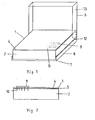
- the device shown in Fig. 1 shows a rectangular insert plate 1, which is arranged on a base plate 7 with lateral boundaries 8.
- the base plate 7 can also have limits on the other sides. It is provided with a foldable protective cover 6, which also has lateral boundaries 13 in this exemplary embodiment.
- the connection of the protective cover 6 to the base plate 7 can be carried out in a known manner, for example by pins 12 arranged in the protective cover 6 or base plate 7 and corresponding openings in the base plate 7 or protective cover 6.
- the carrier plate 1 consists of a hard foam plate 2 of 8 mm Diehl, onto which an inscribable aluminum foil 4 is laminated. The thickness ratios are exaggerated.
- the outlines of two integrated circuits 9 are indicated on the film 4, next to which an also indicated labeling 11 is attached to the surface of the film.
- Fig. 2 shows the insert 1 in cross section with the rigid foam plate 2 and the inscribable film 4, which There is aluminum, as well as a paper layer 5 laminated onto the underside of the aluminum foil 4.
- An integrated circuit 9 protrudes with its connecting legs 10 through the aluminum foil 4 into the foam plate 2 and is thus securely stored. The connection legs of the integrated circuit 9 are short-circuited to one another by the aluminum foil 4, so that damage to the components is not possible.
- rigid rigid foam panels offers the possibility that the receiving device, if used by component manufacturers, can also be equipped mechanically.
Landscapes
- Engineering & Computer Science (AREA)
- Power Engineering (AREA)
- Physics & Mathematics (AREA)
- Condensed Matter Physics & Semiconductors (AREA)
- General Physics & Mathematics (AREA)
- Computer Hardware Design (AREA)
- Microelectronics & Electronic Packaging (AREA)
- Packaging Frangible Articles (AREA)
- Packaging Of Annular Or Rod-Shaped Articles, Wearing Apparel, Cassettes, Or The Like (AREA)
Abstract
Description
Die Erfindung betrifft eine Aufnahmeeinrichtung für elektrische Bauelemente, insbesondere integrierte Schaltkreise, welche mit im wesentlichen parallelen, vom Bauelement weggerichteten Anschlußbeinen versehen sind, mit denen diese Bauelemente in eine Fläche der Aufnahmeeinrichtung einsteckbar sind, die dieserhalb ein leicht von den Anschlußbeinen durchbohrbares, u.a. schaumstoffartiges Material aufweist, wobei die Aufnahmeeinrichtung im Bereich der einzusteckenden AnschluBbeine eine elektrische Leitfähigkeit aufweist, um die gehaltenen elektronischen Bauelemente durch eine ladungsableitende gegenseitige elektrische Verbindung vor Schädigungen zu schützen.The invention relates to a receptacle for electrical components, in particular integrated circuits, which are provided with essentially parallel connection legs facing away from the component, by means of which these components can be inserted into a surface of the receptacle device which, for this reason, can be easily drilled through by the connection legs, i.a. has foam-like material, wherein the receiving device in the region of the connecting legs to be inserted has an electrical conductivity in order to protect the electronic components held against damage by a charge-conducting mutual electrical connection.
Wenn im Sinne dieser Anmeldung von einer Aufnahmeeinrichtung für elektronische Bauelemente gesprochen wird, so ist hiermit eine Einrichtung für Bauelemente gemeint, die sich nicht in ihrem Einbauzustand befinden, sondern die der Lagerung, dem Transport sowie der insbesondere übersichtlichen Aufbewahrung solcher Bauelemente dient. Elektronische Bauelemente, insbesondere integrierte Schaltkreise sind im uneingebauten Zustand bekanntlicherweise verhältnismäßig empfindlich, so daß sie bei Lagerung und Transport einerseits vor mechanischen Beschädigungen, andererseits aber auch vor elektrostatischen Aufladungen zu schützen sind, die zu einer inneren elektrischen Beschädigung der Bauelemente bei programmierten Bauelementen insbesondere zur Löschung der Information führen können.If, in the sense of this application, one speaks of a receiving device for electronic components, this means a device for components which are not in their installed state, but which are used for storage, transport and, in particular, clear storage of such components. Electronic components, in particular integrated circuits, are known to be relatively sensitive when unassembled, so that they are suitable for storage and transport on the one hand, mechanical damage, on the other hand, protection against electrostatic charges, which can lead to internal electrical damage to the components in programmed components, in particular to deletion of the information.
Es sind bereits einfache Schaumstoffplatten von etwa 5 bis 10 mm Dicke bekannt, die aus einem, eine gewisse Steifigkeit aufweisenden Weichschaum bestehen, dem zum Erzeugen einer entsprechenden elektrischen Leitfähigkeit ein Leitfähigkeitsmittel wie beispielsweise Graphit zugegeben ist. Diese Schaumstoffplatten weisen eine sehr dunkle bis schwarze Farbe auf und haben eine verhältnismäßig grobporige Oberfläche, in die sich integrierte Schaltkreise mit ihren Anschlußbeinen hineinstecken lassen. Das Leitfähigkeitsmittel in dem Schaumstoff führt dazu, daß die einzelnen Anschlußbeine des Bauelementes elektrisch leitend miteinander verbunden sind, so daß sich zwischen den einzelnen Anschlüssen eventuell bildende elektrostatische Aufladungen durch elektrische Leitung ausgleichen können. Elektrisch leitende Schaumstoffplatten sind verhältnismäßig teuer.Diese Schaumstoffplatten dienen im wesentlichen dazu, herstellerseitig elektronische Bauelemente ein und desselben Typs für den Versand auf ihnen anzuordnen. Es sind auch schon Schaumstoffplatten bekannt, die an ihrer Oberfläche eine im wesentlichen geschlossene Haut vom Aufschäumen des Materials her aufweisen, oder sogar eine Art Folienkaschierung, wobei diese Folie ein Leitfähigkeitsmittel enthält. Auch hierfür wird im allgemeinen Graphit oder ein kohlenstoffhaltiges Material verwendet, so daß diese Schaumstoffplatten schwarz in ihrer Färbung sind. Außerdem ist ihre Oberflächenstruktur narbig und rauh.Simple foam sheets of approximately 5 to 10 mm thickness are already known, which consist of a soft foam which has a certain rigidity and to which a conductivity agent such as graphite is added to produce a corresponding electrical conductivity. These foam sheets are very dark to black in color and have a relatively large-pored surface, into which integrated circuits with their connecting legs can be inserted. The conductivity agent in the foam means that the individual connection legs of the component are connected to one another in an electrically conductive manner, so that any electrostatic charges which form between the individual connections can be compensated for by electrical conduction. Electrically conductive foam sheets are relatively expensive. These foam sheets are essentially used to place electronic components of the same type on the manufacturer for shipping. Foam sheets are also known which have an essentially closed skin on their surface from the foaming of the material, or even a type of film lamination, this film containing a conductivity agent. For this too, graphite or a carbon-containing material is generally used, so that these foam sheets are black in color. In addition, their surface structure is pitted and rough.
Nun besteht aber nicht nur ein Bedarf an derartigen Trägern für integrierte Schaltkreise zur Versandausrüstung vom Hersteller her. Ein Service-Techniker, der gerufen wird, um einen Schaden an einem elektrischen Gerät zu beseitigen, muß in der Regel eine Vielzahl verschiedener elektronischer Bauelemente mit sich führen, um für alle möglichen Eventualitäten ausgerüstet zu sein. Gleichzeitig soll das Auswechseln des oder der Bauelemente aus Kosten- und Zeitgründen möglichst schnell vor sich gehen. In der Regel fehlt es dem Service-Techniker an einer übersichtlichen Aufbewahrungsmöglichkeit für die verschiedenen elektronischen Bauelemente, so daß ein schnelles Auswählen des benötigten Bauelementes nicht gewährleistet ist. Insbesondere ist es häufig notwendig, jedes einzelne Bauelement in die Hand zu nehmen, um anhand des kleinen Typenaufdrucks auszumachen, ob es sich um das gewünschte Bauelement handelt oder nicht.Now there is not only a need for such carriers for integrated circuits for shipping equipment from Manufacturer. A service technician who is called in to repair damage to an electrical device usually has to carry a large number of different electronic components with him in order to be equipped for all possible contingencies. At the same time, the replacement of the component or components should take place as quickly as possible for reasons of cost and time. As a rule, the service technician lacks a clear storage option for the various electronic components, so that a quick selection of the required component is not guaranteed. In particular, it is often necessary to take each individual component in hand in order to tell from the small type label whether it is the desired component or not.
Der vorliegenden Erfindung liegt daher in erster Linie die Aufgabe zugrunde, eine Aufnahmeeinrichtung der eingangs genannten Art für elektronische Bauelemente zu schaffen, die diese Bauelemente nicht nur vor mechanischen Beschädigungen schützt und eine elektrisch leitende Verbindung zwischen den Anschlußbeinen gewährleistet, um für eine Ableitung elektrostatischer Ladungen zu sorgen, sondern die es insbesondere dem Service-Techniker auch ermöglicht, Bauteile in übersichtlicher Form anzuordnen, wobei jedem Bauteil mit gebrauchsüblichen Mitteln eine gut sichtbare Kennzeichnung zugeordnet werden kann, so daß die Bauteile gut erkennbar und unterscheidbar sind, ohne sie ihrem Träger entnehmen zu müssen. In besonderer Ausführungsform soll die Aufnahmeeinrichtung zusätzlich eine besonders gute Handhabbarkeit aufweisen, so daß sie in Service-Koffern oder anderen Behältnissen problemlos mitgeführt werden kann, ohne daß ein besonderes Augenmerk auf die Schonung der elektronischen Bauelemente gelegt zu werden braucht.The present invention is therefore primarily based on the object to provide a receiving device of the type mentioned for electronic components, which not only protects these components from mechanical damage and ensures an electrically conductive connection between the connection legs in order to discharge electrostatic charges care, but which also enables the service technician in particular to arrange components in a clear form, whereby each component can be assigned a clearly visible marking using customary means, so that the components are easily recognizable and distinguishable without having to remove them from their carrier . In a special embodiment, the receiving device should also be particularly easy to handle, so that it can easily be carried in service cases or other containers without having to pay particular attention to the protection of the electronic components.
Diese Aufgabe wird erfindungsgemäß dadurch gelöst, daß die Einsteckfläche der Afnahmeeinrichtung eine von den Anschlußbeinen des elektronischen Bauelementes durchstechbare, auf ihrer freien Außenoberfläche mit einem handelsüblichen Schreibgerät beschriftbare Folie aufweist, unter der das schaumstoffartige Material angeordnet ist, wobei diese Außenoberfläche einen genügend niedrigen Lichtabsorptionsgrad aufweist, um auf ihr angebrachte Informationen mit genügendem Kontrast dem menschlichen Auge erkennbar zu machen.This object is achieved in that the insertion surface of the receiving device one of the connection Legs of the electronic component pierceable, on its free outer surface with a commercially available writing utensil, under which the foam-like material is arranged, this outer surface having a sufficiently low level of light absorption to make it visible to the human eye with sufficient contrast information attached to it.
Wenn hier von einer Folie die Rede ist, die mit handelsüblichen Mitteln beschriftbar sein soll, so ist dabei unter anderem an Faserschreiber oder Filzschreiber gedacht, wie sie beispielsweise zur Beschriftung von Folien für Over-Head-Projektoren geläufig sind. Solche Schreiber sind überall im Handel erhältlich. Für die Beschriftbarkeit ist es ferner angebracht, daß die Folie möglichst nicht die genarbte oder Porenstruktur der darunterliegenden Schaumstoffplatte aufweist, weil dann eine Beschriftung ihrer Oberfläche nicht in ausreichend kleinem Maße möglich ist. Wenn hier von einem geringen Absorptionsgrad der Oberfläche für Licht zum Zwecke des Gewährleistens eines bestimmten Kontrastes gegenüber den aufgebrachten Schriftzeichen gesprochen wird, so soll hierunter ein Absorptionsgrad der Oberfläche von weniger als 0,8 verstanden werden.If we are talking about a film that should be writable using commercially available means, we are thinking here, among other things, of fiber pens or felt pens, such as are commonly used for marking films for overhead projectors. Such writers are commercially available everywhere. For the ability to be written on, it is also appropriate that the film preferably does not have the grained or pore structure of the underlying foam sheet, because then it is not possible to label its surface to a sufficiently small extent. If one speaks here of a low degree of absorption of the surface for light for the purpose of ensuring a certain contrast with respect to the characters applied, this should be understood to mean a degree of absorption of the surface of less than 0.8.
Das unterhalb der Folie verwendete schaumstoffartige Material sollte eine im wesentlichen steife Hartschaumplatte sein, die für die Handhabung eine genügende Eigenstabilität aufweist, die aber eine ausreichende Weichheit bzw. Durchdringungsfähigkeit besitzt, um die Anschlußbeine der elektronischen Bauelemente ohne Beschädigung und Verbiegen einstecken zu können. Die beschriftbare Folie ist auf die Hartschaumplatte aufkaschiert.The foam-like material used below the film should be an essentially rigid rigid foam plate which has sufficient inherent stability for handling, but which has sufficient softness or penetrability in order to be able to insert the connecting legs of the electronic components without damage and bending. The inscribable film is laminated onto the hard foam plate.
Die Folie kann grundsätzlich eine Kunststoffolie sein, die jedoch zum Erzeugen der erforderlichen Kontrastfähigkeit ein möglichst opakes helles Pigment enthalten sollte. Die elektrische Leitfähigkeit der Einsteckfläche kann entweder durch eine entsprechend leitfähige Beschichtung der Folie gegeben sein, die beispielsweise aus Zinnoxid oder Indiumoxid besteht, sie kann aber auch, wie bereits bekannt, durch entsprechende Ausrüstung des Schaumstoffmaterials vorgegeben werden, obwohl diese Ausführung teuer ist und den Nachteil hat, durch Berührung entstehende, elektrostatische Oberflächenladungen der Folie nicht genügend abzu-leiten.The film can in principle be a plastic film, but it is used to create the required contrast should contain a light pigment that is as opaque as possible. The electrical conductivity of the insertion surface can either be given by a correspondingly conductive coating of the film, which consists for example of tin oxide or indium oxide, but it can also, as already known, be specified by appropriate equipment of the foam material, although this design is expensive and has the disadvantage does not adequately dissipate electrostatic surface charges on the film caused by touch.
Eine besonders vorteilhafte Ausführungsform der Erfindung besteht darin, als beschriftbare Folie eine Metallfolie, insbesondere eine Aluminiumfolie zu verwenden, die auf das durch die Anschlußbeine der Bauelemente durchdringbare Plattenmaterial aufkaschiert ist. Eine Aluminiumfolie weist nicht nur eine erstklassige elektrische Leitfähigkeit auf, sie ist bei entsprechender Dickenausführung, wie sie im Haushalts- und Verpackungssektor üblich ist, durch die empfindlichen Beine der elektronischen Bauelemente leicht durchstechbar und weist nicht den anfänglichen Durchdringungswiderstand aus, wie er bei Kunststoffolien beobachtet wird, die sich oft erst nach erheblicher Verformung und Eindrückung der Oberfläche durchstechen lassen. Die gewisse Tendenz einer Aluminiumfolie, an den Durchstichstellen leicht weiter aufzureißen, wodurch ein elektrischer Kontakt mit den Anschlußbeinen des elektronischen Bauteiles in Frage gestellt werden könnte, läßt sich vorteilhafterweise dadurch verringern, daß man eine Aluminiumfolie verwendet, die mit einer Papierschicht kaschiert ist. Solche papierkaschierten Aluminiumfolien sind problemlos herstellbar und aus dem Verpackungssektor bekannt. Die Papierschicht ist an derjenigen Seite der Folie anzuodrnen, die der Schaumstoffplatte zugewandt ist. Hieraus resultiert der weitere Vorteil, daß sich die Aluminiumfolie mittels der Papierschicht leicht auf eine Schaumstoffplatte aufkaschieren läßt, was bei Verwendung einer reinen Metallfolie auf gewisse Schwierigkeiten stoßen könnte. Aluminiumfolien lassen sich in ihrer Oberfläche durchaus so ausrüsten, daß sie mit den erwähnten Schreibgeräten leicht beschriftbar sind. Eine entsprechende Kontrastwirkung ist bei der Aluminiumfolie auch gegeben. Wenn im vorliegenden Zusammenhang von Aluminiumfolien gesprochen wird, so soll dieser Begriff nicht auf die handelsübliche Definition beschränkt sein, der Folien von 7 p bis etwa 20 p Diehl umfaßt, sondern auch das sogenannte Aluminiumdünnband mit umfassen, welches den Dickenbereich von etwa 20 p bis 0,2 mm einschließt. Es bereitet dem Fachmann keine Schwiereigkeiten aus den angegebenen Dickenbereichen eine geeignete Folie für die Erfindung auszuwählen. Bei papierkaschierten Aluminiumfolien wird im allgemeinen ein Trägerpapier von 50 g/m2 verwendet. Bei der Verwendung einer solchen kaschierten Folie kann die Aluminiumschicht natürlich entsprechend dünner sein, da auch dünnste Folien in jedem Fall noch die geforderten Leitfähigkeitseigenschaften aufweisen.A particularly advantageous embodiment of the invention consists in using a metal foil, in particular an aluminum foil, as the inscribable foil, which is laminated onto the plate material that can be penetrated through the connecting legs of the components. Not only does aluminum foil have first-class electrical conductivity, it is easily pierceable with the appropriate thickness, as is common in the household and packaging sector, through the sensitive legs of the electronic components and does not show the initial resistance to penetration, as is observed with plastic foils , which can often only be pierced after considerable deformation and indentation of the surface. The certain tendency of an aluminum foil to tear open easily at the piercing points, which could put electrical contact with the connection legs of the electronic component in question, can advantageously be reduced by using an aluminum foil which is laminated with a paper layer. Such paper-clad aluminum foils can be produced without any problems and are known from the packaging sector. The paper layer must be attached to the side of the film that faces the foam sheet. This results in the further advantage that the aluminum foil can be easily laminated onto a foam sheet by means of the paper layer, which could encounter certain difficulties when using a pure metal foil. The surface of aluminum foils can be equipped in such a way that they can be easily written on using the writing instruments mentioned. The aluminum foil also has a corresponding contrast effect. When speaking in the present context of aluminum foils, this term should not be restricted to the commercial definition which includes foils from 7 p to about 20 p Diehl, but also include the so-called aluminum thin strip, which has the thickness range from about 20 p to 0 , 2 mm. It is not difficult for the person skilled in the art to select a suitable film for the invention from the specified thickness ranges. In the case of paper-clad aluminum foils, a backing paper of 50 g / m2 is generally used. When using such a laminated film, the aluminum layer can of course be correspondingly thinner, since even the thinnest films still have the required conductivity properties.
Der besondere Vorteil dieser bevorzugten Ausführungsform der Erfindung beruht darin, daß gerade die Oberfläche der Aufnahmeeinrichtung eine hohe Leitfähigkeit aufweist, so daß elktrostatische Oberflächenladungen, die bei Kunststoffmaterialien allein durch Berühren schon entstehen können, sich hier nicht ausbilden können.The particular advantage of this preferred embodiment of the invention resides in the fact that the surface of the receiving device in particular has a high conductivity, so that electrostatic surface charges, which can arise in plastic materials simply by touching them, cannot form here.
Bei der Herstellung von Aluminiumfolien fallen diese herstellungsbedingt mit einer glänzenden und einer matten Seite an. Während für Verpackungszwecke meist die matte Seite mit der Papierschicht kaschiert wird, ist es für eine Verwendung im Rahmen dieser Erfindung besonders zweckmäßig, die matte Seite der Aluminiumfolie als Oberfläche der Aufnahmeeinrichtung zu verwenden. Beschriftungen weisen auf der matten Seite einen besseren Kontrast auf und lassen sich daher besser erkennen. Zweckmäßigerweise werden für die erfindungsgemäße Aufnahmeeinrichtung Hartschaumplatten im Dickenbereich von 5-10 mm verwendet.When manufacturing aluminum foils, they are produced with a glossy and a matt side. While the matt side is usually laminated with the paper layer for packaging purposes, it is particularly expedient for use in the context of this invention to use the matt side of the aluminum foil as the surface of the receiving device. Inscriptions have a better contrast on the matt side and are therefore easier to recognize. Expediently for the recording device according to the invention uses hard foam panels in the thickness range of 5-10 mm.
Eine bevorzugte Ausführungsform der Aufnahmeeinrichtung besteht darin, beide Seiten der Hartschaumplatte mit einer Aluminiumfolie zu versehen. Dies hat nicht nur den Vorteil, daß solche Trägerplatten durch Wenden auch noch von der anderen Seite durch Gebrauch bereits stark zerstochen oder mit nicht mehr benötigten Informationen versehen ist, die doppelseitige Belegung der Hartschaumplatte mit einer Aluminiumfolie hat auch den Vorteil, daß die Platte sichwechselnden Temperatureinflüssen weniger verwirft oder krümmt.A preferred embodiment of the receiving device consists in providing both sides of the hard foam plate with an aluminum foil. This not only has the advantage that such carrier plates are already severely pricked from use on the other side by use or are provided with information that is no longer required, the double-sided covering of the hard foam plate with an aluminum foil also has the advantage that the plate is subject to changing temperature influences less warps or warps.
Bei der vorstehend beschriebenen bevorzugten Ausführungsform unter Verwendung einer Metall-, insbesondere Aluminiumfolie, bietet sich natürlich auch die Möglichkeit, die Folie von vornherein im Druckwege mit bestimmten Anordnungsfeldern für die elektronischen Bauelemente und/oder erforderlichen Informationen zu versehen. Eine solche Ausführung des erfindungsgemäßen Plattenmaterials kann auch für dessen Verwendung für den herstellerseitigen Versand von besonderem Interesse sein. Typenbezeichnungen, Bauelementinformationen und Firmen- bzw. Werbeangaben können von vornherein auf der erfindungsgemäßen Aufnahmeeinrichtung angebracht werden.In the preferred embodiment described above using a metal, in particular aluminum foil, there is of course also the possibility of providing the foil with certain arrangement fields for the electronic components and / or necessary information from the outset in the printing path. Such an embodiment of the plate material according to the invention can also be of particular interest for its use for shipping by the manufacturer. Type designations, component information and company or advertising information can be attached to the receiving device according to the invention from the outset.
Ein besonderer Aspekt der Erfindung in bevorzugter Ausführungsform liegt jedoch darin, die Aufnahmeeinrichtung in Gestalt eines Behälters oder einer Kassette auszubilden, die darüber hinaus in einem Format ausgeführt ist, daß sie dem Service-Techniker eine einfache Handhabbarkeit bietet, d.h. in normalen Service-Koffern und Aktentaschen mitführbar ist. Hier kommen Größen im Format DIN A4 oder auch kleiner in Frage. Vorteilhafterweise weist eine solche Einheit eine Mehrzahl der erfindungsgemäß ausgebildeten Einsteckflächen auf. Wenn hier von Behältern oder Kassetten die Rede ist, so können darunter sowohl ringbuchartige Anordnungen verstanden werden, in die die einzelnen Einsteckflächen bzw. Einsteckplatten seitenartig eingehängt sind, wie auch mit Deckel versehene, geschlosse Kassetten, wie sie beispielsweise heute für die Aufnahme von elektronischen Speicherdisketten verwendet werden. Bei erfindungsgemäßer Ausführung der Einsteckflächen kann der Service-Techniker ein von ihm benötigtes Sortiment an elektronischen Bauteilen in die Flächen einstecken und neben den Bauteilen eine benötigte Kennzeichnung oder Informationsbeschriftung anbringen. Es ist auch möglich, derartige Kennzeichnungen von vornherein durch Aufdruck vorzugeben, so daß bestimmte Bauelemente an einem speziell dafür vorgesehenen Platz angeordnet werden können. Aber auch in diesem Fall ist dann zusätzlich die Möglichkeit gegeben, daß der Benutzer der Aufnahmeeinrichtung noch eigene Informationen hinzufügen kann.A particular aspect of the invention in a preferred embodiment, however, is to design the receiving device in the form of a container or a cassette, which is also designed in a format that it offers the service technician easy handling, ie in normal service cases and Briefcases can be carried. Sizes in A4 format or smaller are possible here. Such a unit advantageously has a plurality of the insertion surfaces designed according to the invention. If here from containers or cassettes It is meant that both ring binder-like arrangements in which the individual plug-in surfaces or plug-in plates are suspended in a page-like manner, as well as closed cassettes provided with a cover, such as are used today for accommodating electronic storage disks, for example. In the inventive design of the plug-in surfaces, the service technician can insert a range of electronic components that he requires into the surfaces and, in addition to the components, attach a required identification or information label. It is also possible to specify such markings from the outset by printing, so that certain components can be arranged in a place specially provided for this purpose. But even in this case there is also the possibility that the user can add his own information to the recording device.
In weiterhin bevorzugter Ausführungsform ist die Kassette, das Gehäuse oder der Behälter selbst mit einer elektrisch leitenden Beschichtung oder Ausrüstung versehen, um elektrostatische Ladungen ableiten zu können, bevor diese überhaupt in den Bereich der gehalterten elektronischen Bauelemente gelangen können. Auch diese elektrische Leitfähigkeitsausrüstung des Gehäuses kann durch eine Aluminiumfolienkaschierung erreicht werden. Ferner kann es zweckmäßig sein, das Gehäuse strahlungsabsorbierend auszurüsten. Mit Programmspeicherung versehene Speicherbauelemente, sog. PROM's sind gegen Röntgenstrahlen empfindlich, wie sie beispielsweise bei den Durchleuchtungen zur Flughafenabsicherung eingesetzt werden. Die Bestrahlung kann dazu führen, daß die gespeicherten Daten in solchen PROM's gelöscht werden. Da sich gerade Service-Techniker oft des Flugzeuges zur schnellen Behebung von Störungen bedienen, kann eine Ausführungsform der erfindungsgemäßen Aufnahmeeinrichtung vorteilhaft sein, bei der die Kassette oder das Gehäuse gegen Strahlung oder auch elektromagnetisch geschützt ist. Dies läßt sich durch geeignete Einlagen oder Kaschierungen aus Blei bzw. nur der Leitfähigkeit dienenden Metallen erreichen.In a further preferred embodiment, the cassette, the housing or the container itself is provided with an electrically conductive coating or equipment in order to be able to discharge electrostatic charges before they can even reach the area of the held electronic components. This electrical conductivity equipment of the housing can also be achieved by aluminum foil lamination. Furthermore, it may be appropriate to equip the housing with radiation absorption. Memory components provided with program storage, so-called PROMs, are sensitive to X-rays, such as those used for fluoroscopy for airport security. Irradiation can cause the stored data in such PROMs to be deleted. Since service technicians in particular often use the aircraft for the rapid rectification of faults, an embodiment of the recording device according to the invention can be advantageous in which the cassette or the Housing is protected against radiation or electromagnetically. This can be achieved by using suitable inlays or laminations made of lead or only metals that serve for conductivity.
Im folgenden wird die Erfindung anhand der in den Zeichnungen dargestellten Ausführungsbeispiele im einzelnen zusätzlich erläutert. Es stellen dar:
- Fig. 1 eine bevorzugte Aufnahmeeinrichtung in perspektivischer Ansicht und
- Fig. 2 einen Schnitt durch die Trägerplatte dieser Aufnahmeeinrichtung.
- Fig. 1 shows a preferred receiving device in a perspective view
- Fig. 2 shows a section through the carrier plate of this receiving device.
Die in Fig. 1 dargestellte Einrichtung zeigt eine rechteckige Einsteckplatte 1, die auf einer Bodenplatte 7 mit seitlichen Begrenzungen 8 angeordnet ist. Die Bodenplatte 7 kann auch an den übrigen Seiten Begrenzungen aufweisen. Sie ist mit einer klappbaren Schutzabdeckung 6 versehen, die in diesem Ausführungsbeispiel ebenfalls seitliche Begrenzungen 13 aufweist. Die Verbindung der Schutzabdeckung 6 mit der Bodenplatte 7 kann in bekannter Art und Weise, beispielsweise durch in der Schutzabdeckung 6 oder Bodenplatte 7 angeordnete Stifte 12 und entsprechende Öffnungen in der Bodenplatte 7 bzw. Schutzabdeckung 6 ausgeführt sein. Die Trägerplatte 1 besteht aus einer Hartschaumplatte 2 von 8 mm Diehl, auf die eine beschriftbare Aluminiumfolie 4 aufkaschiert ist. Die Dickenverhältnisse sind übertrieben dargestellt. In Fig. l sind auf der Folie 4 die Umrisse zweier integrierter Schaltkreise 9 angedeutet, neben denen eine ebenfalls angedeutete Kennzeichnungsbeschriftung 11 auf der Oberfläche der Folie angebracht ist.The device shown in Fig. 1 shows a
Fig. 2 zeigt die Einsteckplatte 1 im Querschnitt mit der Hartschaumplatte 2 und der beschriftbaren Folie 4, die aus Aluminium besteht, sowie eine auf die Unterseite der Aluminiumfolie 4 aufkaschierte Papierschicht 5. Ein integrierter Schaltkreis 9 ragt mit seinen Anschlußbeinen 10 durch die Aluminiumfolie 4 hindurch in die Schaumstoffplatte 2 hinein und ist somit sicher gelagert. Durch die Aluminiumfolie 4 werden die Anschlußbeine des integrierten Schaltkreises 9 gegeneinander kurzgeschlossen, so daß eine Beschädigung der Bauelemente nicht möglich ist.Fig. 2 shows the
Die Verwendung steifer Hartschaumplatten bietet die Möglichkeit, daß die Aufnahmeeinrichtung, wenn sie von Bauelemente-Herstellern verwendet wird, auch maschinell bestückt werden kann.The use of rigid rigid foam panels offers the possibility that the receiving device, if used by component manufacturers, can also be equipped mechanically.
Claims (10)
Applications Claiming Priority (2)
| Application Number | Priority Date | Filing Date | Title |
|---|---|---|---|
| DE8436362U | 1984-12-12 | ||
| DE8436362 | 1984-12-12 |
Publications (1)
| Publication Number | Publication Date |
|---|---|
| EP0184849A1 true EP0184849A1 (en) | 1986-06-18 |
Family
ID=6773682
Family Applications (1)
| Application Number | Title | Priority Date | Filing Date |
|---|---|---|---|
| EP19850115884 Withdrawn EP0184849A1 (en) | 1984-12-12 | 1985-12-12 | Pick-up device for electronic components |
Country Status (1)
| Country | Link |
|---|---|
| EP (1) | EP0184849A1 (en) |
Cited By (2)
| Publication number | Priority date | Publication date | Assignee | Title |
|---|---|---|---|---|
| EP0284549A2 (en) * | 1987-03-24 | 1988-09-28 | Silica Gel Ges.mbH Absorptionstechnik, Apparatebau | Magnetic fluid compositions |
| DE202024100655U1 (en) | 2023-02-22 | 2024-03-19 | Kerstin Krumbeck | Carrier for holding objects |
Citations (6)
| Publication number | Priority date | Publication date | Assignee | Title |
|---|---|---|---|---|
| US2518450A (en) * | 1944-11-08 | 1950-08-15 | Sidney T V Cowen | Cushioned package of fragile articles |
| US3092245A (en) * | 1960-12-29 | 1963-06-04 | Clevite Corp | Package for miniature electrical components |
| US4274537A (en) * | 1979-09-24 | 1981-06-23 | Cosmetex, Inc. | Integrated circuit storage catalog |
| US4333565A (en) * | 1981-02-27 | 1982-06-08 | Woods Larry N | Anti-static package for electronic chips |
| US4404615A (en) * | 1981-12-14 | 1983-09-13 | United Plastics, Corp. | Anti-static container for electronic components |
| US4487315A (en) * | 1983-02-24 | 1984-12-11 | Fujimori Kogyo Co., Ltd. | Tube assembly for integrated circuits |
-
1985
- 1985-12-12 EP EP19850115884 patent/EP0184849A1/en not_active Withdrawn
Patent Citations (6)
| Publication number | Priority date | Publication date | Assignee | Title |
|---|---|---|---|---|
| US2518450A (en) * | 1944-11-08 | 1950-08-15 | Sidney T V Cowen | Cushioned package of fragile articles |
| US3092245A (en) * | 1960-12-29 | 1963-06-04 | Clevite Corp | Package for miniature electrical components |
| US4274537A (en) * | 1979-09-24 | 1981-06-23 | Cosmetex, Inc. | Integrated circuit storage catalog |
| US4333565A (en) * | 1981-02-27 | 1982-06-08 | Woods Larry N | Anti-static package for electronic chips |
| US4404615A (en) * | 1981-12-14 | 1983-09-13 | United Plastics, Corp. | Anti-static container for electronic components |
| US4487315A (en) * | 1983-02-24 | 1984-12-11 | Fujimori Kogyo Co., Ltd. | Tube assembly for integrated circuits |
Cited By (5)
| Publication number | Priority date | Publication date | Assignee | Title |
|---|---|---|---|---|
| EP0284549A2 (en) * | 1987-03-24 | 1988-09-28 | Silica Gel Ges.mbH Absorptionstechnik, Apparatebau | Magnetic fluid compositions |
| EP0284549B1 (en) * | 1987-03-24 | 1992-07-15 | Silica Gel Ges.mbH Absorptionstechnik, Apparatebau | Magnetic fluid compositions |
| DE202024100655U1 (en) | 2023-02-22 | 2024-03-19 | Kerstin Krumbeck | Carrier for holding objects |
| DE102023000628A1 (en) | 2023-02-22 | 2024-08-22 | Kerstin Krumbeck | Carrier for holding objects |
| EP4420835A1 (en) | 2023-02-22 | 2024-08-28 | Kerstin Krumbeck | Carrier for receiving objects |
Similar Documents
| Publication | Publication Date | Title |
|---|---|---|
| DE69520717T2 (en) | Cassette, storage case, and label for the same cassette and storage case | |
| EP0065083A1 (en) | Identitity card incorporating an IC chip | |
| DE3124886A1 (en) | DISK RECORDING HOUSING | |
| EP0184849A1 (en) | Pick-up device for electronic components | |
| DE2943853C3 (en) | Device for holding sheet-shaped X-ray films | |
| DE3728341C2 (en) | ||
| DE2751680A1 (en) | SWITCH MATRIX, IN PARTICULAR TRANSPARENT SWITCH MATRIX, FOR KEY AREA DEVICES | |
| DE102018130600A1 (en) | Magnetic privacy filter | |
| DE9216771U1 (en) | Case for storing compact discs in particular | |
| DE102019115822A1 (en) | Closure device for reversibly closing a lens, an opening or a unit of an object | |
| DE2943854C2 (en) | X-ray fluorescence intensifying screen with a flexible support and a fluorescent layer applied to it | |
| DE2901978A1 (en) | FILM TAPE | |
| DE4224011C2 (en) | Card with information carrier for recording emergency data | |
| DE8903977U1 (en) | Packaging of a compact disc | |
| DE8005177U1 (en) | COVER FOR REPEATABLE RECORDS | |
| DE202022103403U1 (en) | Packaging for a compact disc and printed matter | |
| DE19722706C1 (en) | Flat transparent folder | |
| DE535412C (en) | Cassette frame for X-ray exposures | |
| DE8306209U1 (en) | Receipt card, especially for examination results in hospitals, clinics, etc. | |
| DE8436362U1 (en) | Device for storing electronic components | |
| DE29812869U1 (en) | Multi-layer information board | |
| DE640783C (en) | Cassette for X-ray films | |
| DE8331191U1 (en) | Video cassette case | |
| DE3911842A1 (en) | Diagram disc for patient guidance and monitoring | |
| DE9206742U1 (en) | Device for handling sheet-like documents |
Legal Events
| Date | Code | Title | Description |
|---|---|---|---|
| PUAI | Public reference made under article 153(3) epc to a published international application that has entered the european phase |
Free format text: ORIGINAL CODE: 0009012 |
|
| AK | Designated contracting states |
Kind code of ref document: A1 Designated state(s): AT BE CH DE FR GB IT LI NL |
|
| 17P | Request for examination filed |
Effective date: 19861204 |
|
| STAA | Information on the status of an ep patent application or granted ep patent |
Free format text: STATUS: THE APPLICATION IS DEEMED TO BE WITHDRAWN |
|
| 18D | Application deemed to be withdrawn |
Effective date: 19880705 |