EP0184447B1 - Automobile antenna system - Google Patents
Automobile antenna system Download PDFInfo
- Publication number
- EP0184447B1 EP0184447B1 EP85308843A EP85308843A EP0184447B1 EP 0184447 B1 EP0184447 B1 EP 0184447B1 EP 85308843 A EP85308843 A EP 85308843A EP 85308843 A EP85308843 A EP 85308843A EP 0184447 B1 EP0184447 B1 EP 0184447B1
- Authority
- EP
- European Patent Office
- Prior art keywords
- antenna
- vehicle body
- pick
- frequency
- automobile
- Prior art date
- Legal status (The legal status is an assumption and is not a legal conclusion. Google has not performed a legal analysis and makes no representation as to the accuracy of the status listed.)
- Expired - Lifetime
Links
Images


Classifications
-
- H—ELECTRICITY
- H01—ELECTRIC ELEMENTS
- H01Q—ANTENNAS, i.e. RADIO AERIALS
- H01Q1/00—Details of, or arrangements associated with, antennas
- H01Q1/27—Adaptation for use in or on movable bodies
- H01Q1/32—Adaptation for use in or on road or rail vehicles
- H01Q1/325—Adaptation for use in or on road or rail vehicles characterised by the location of the antenna on the vehicle
- H01Q1/3275—Adaptation for use in or on road or rail vehicles characterised by the location of the antenna on the vehicle mounted on a horizontal surface of the vehicle, e.g. on roof, hood, trunk
-
- H—ELECTRICITY
- H01—ELECTRIC ELEMENTS
- H01Q—ANTENNAS, i.e. RADIO AERIALS
- H01Q1/00—Details of, or arrangements associated with, antennas
- H01Q1/27—Adaptation for use in or on movable bodies
- H01Q1/32—Adaptation for use in or on road or rail vehicles
-
- H—ELECTRICITY
- H04—ELECTRIC COMMUNICATION TECHNIQUE
- H04B—TRANSMISSION
- H04B7/00—Radio transmission systems, i.e. using radiation field
- H04B7/02—Diversity systems; Multi-antenna system, i.e. transmission or reception using multiple antennas
- H04B7/04—Diversity systems; Multi-antenna system, i.e. transmission or reception using multiple antennas using two or more spaced independent antennas
- H04B7/08—Diversity systems; Multi-antenna system, i.e. transmission or reception using multiple antennas using two or more spaced independent antennas at the receiving station
- H04B7/0802—Diversity systems; Multi-antenna system, i.e. transmission or reception using multiple antennas using two or more spaced independent antennas at the receiving station using antenna selection
- H04B7/0805—Diversity systems; Multi-antenna system, i.e. transmission or reception using multiple antennas using two or more spaced independent antennas at the receiving station using antenna selection with single receiver and antenna switching
- H04B7/0814—Diversity systems; Multi-antenna system, i.e. transmission or reception using multiple antennas using two or more spaced independent antennas at the receiving station using antenna selection with single receiver and antenna switching based on current reception conditions, e.g. switching to different antenna when signal level is below threshold
Definitions
- the present invention relates to space diversity reception type automobile antenna systems.
- Antenna systems are essential for modern automobiles which must positively receive radio or other waves at their built-in receivers. Antenna systems are also very important for citizen band transceivers to effect the transmission and reception of waves between an automobile and other stationary or moving stations.
- pole type antenna which projects outwardly from the vehicle body and exhibits a favorable reception performance.
- the pole type antenna tends to interfere with the design of automobiles.
- Radio waves belonging to relatively high frequency bands tend to propagate rectilinearly.
- Direct waves tend to interfere with waves reflected by buildings and/or mountains to create a distortion in the waves, or multi-path noise, by which voice signals are momentarily interrupted.
- a single pole antenna cannot reduce such multi-path noise when receiving waves belonging to high frequency bands.
- the pole type antenna is directional, moreover, the reception of waves varies when the direction of a moving automobile changes relative to the incoming waves. It is therefore difficult to receive radio waves steadily at a moving automobile utilizing a single pole antenna.
- a diversity reception type automobile antenna system comprising a pole antenna and a rod-like sub-antenna which are spaced apart from one another.
- the antenna which can more efficiently receive waves at any one time is automatically selected to improve the directional pattern in the entire antenna system.
- FR-A-2266428 describes a space diversity automobile antenna system comprising: first and second antenna means associated with the automobile to detect broadcast radio frequency signals and to provide respective first and second output signals; switch means operable in response to a change in the level of a said output signal to select one of said output signals for use; and said first antenna means comprising a pole type antenna mounted at a first location on the vehicle body.
- the second antenna means is also a pole type antenna which also projects outwardly from the vehicle body.
- JP-A-5870640 describes a space diversity automobile antenna system in which the first and second antenna means are respectively a loop antenna of the magnetic field reception type and an antenna of the electric field reception type.
- the present invention is characterized in that: said second antenna means comprises a pick-up to detect broadcast radio frequency signals at a frequency above 50 MHz; said pick-up being mounted at a second location on said body, spaced from said first location, and adjacent a metal structure forming an elongate connection between first and second adjacent generally flat metal body portions to detect radio frequency surface currents induced in said structure by the broadcast radio frequency signals; and each said pick-up comprises a casing having an opening and a loop antenna disposed within the casing with a side thereof exposed through said opening to extend closely adjacent and substantially parallel to an elongate surface portion of said structure along which said surface currents have a concentrated flow.
- Such a high-frequency pick-up can readily be installed on the vehicle body without damaging the aesthetic appearance of the vehicle body.
- Figure 1 is a perspective view of an automobile having one embodiment of a space diversity reception type automobile antenna system according to the present invention, which comprises a pole antenna outwardly projecting from the rearward portion of the vehicle and a high-frequency pick-up mounted in one of the front pillars of the vehicle body.
- Figure 2 illustrates the position of the high-frequency pick-up in the front pillar.
- Figure 3 is a cross-sectional view of an electromagnetic coupling type high-frequency pick-up mounted in the front pillar shown in Figure 2.
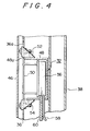
- Figure 4 is a longitudinal section of the primary parts of the construction shown in Figure 3.
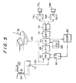
- Figure 5 is a circuit diagram of the automobile antenna system.
- Figure 6 illustrates the directional patterns of the pole antenna and the high-frequency pick-up.
- Figure 7 is a perspective view of an automobile having another embodiment of the space diversity reception type automobile antenna system which comprises a pole antenna mounted on a front and right-hand pillar of the vehicle body and a high-frequency pick-up mounted on one of the trunk hinges on the same vehicle body.
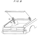
- Figure 8 is a perspective view showing the mounting of the high-frequency pick-up on the trunk hinge.
- Figure 9 is a longitudinal section of the primary parts shown in Figure 8.
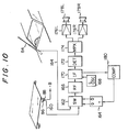
- FIG 10 is a circuit diagram of the autombile antenna system shown in Figures 7 to 9.
- Figure 11 illustrates the directional patterns of the pole antenna and high-frequency pick-up shown in Figures 7 to 10.
- Figure 12 illustrates surface currents I induced on the vehicle body B by external waves W.
- Figure 13 illustrates a probe and its processing circuit used to determine the distribution of surface currents on the vehicle body, the probe being constructed and functioning in accordance with the same principle as that of the high-frequency pick-up used in the present invention.
- Figure 14 illustrates the electromagnetic coupling between the surface currents I and a loop antenna in the pick-up.
- Figure 15 illustrates the directional pattern of the loop antenna shown in Figure 14.
- Figure 16 illustrates the distribution of surface current intensity on the vehicle body.
- Figure 17 illustrates the orientation of surface currents on the vehicle body.
- FIG. 12 to 17 there is shown a process of ascertaining the distribution of surface currents on the vehicle body and determining a location at which an automobile antenna system according to the present invention can most efficiently operate.
- Figure 12 shows the fact that when external waves W such as radio or other waves pass through the vehicle body B of electrically conductive metal, surface currents I are induced on the vehicle body at various locations at a level corresponding to the intensity of the external waves.
- the present invention is intended to receive radio or other waves belonging to bands of relatively high frequencies which are typically equal to or higher than 50 MHz.
- the distribution of surface currents induced on the vehicle body by radio or waves belonging to these bands are measured to determine a location at which the density of surface currents is higher with less noise.
- a simulation is carried out by the use of a computer and also the intensity of currents is actually measured on the vehicle body at various locations.
- the actual measurements of current intensity are made by using a probe constructed and functioning in accordance with the same principle as that of a high-frequency pick-up which is included in an automobile antenna system according to the present invention, as will be described hereinafter.
- the probe is moved over the entire surface of the vehicle body while being angularly rotated at the respective locations on the vehicle body.
- FIG. 13 shows a probe P suitable for use in such measurement.
- the probe P includes a casing 10 of electrically conductive material and a loop coil 12 located within the casing 10 and shielded from any undesirable external waves by the casing 10.
- the casing 10 is provided with an opening 10a through which a portion of the loop coil 12 is externally exposed.
- the exposed portion of the loop coil 12 is disposed in close proximity to the surface of the vehicle body B such that the loop coil 12 can detect a magnetic flux formed by the surface currents on the vehicle body.
- the loop coil 12 is electrically connected to the casing 10 through a short-circuiting line 14.
- the output terminal 16 of the loop coil 12 is electrically connected to a core 20 in a coaxial cable 18.
- the loop coil 12 includes a capacitor 22 for causing the frequency of the loop coil 12 to resonate with a desired frequency to be measured to improve the efficiency of picking-up.
- the output of the probe P is amplified by a high-frequency voltage amplifier 24 the output voltage of which in turn is measured by a high-frequency voltage measuring device 26.
- the output voltage measured by the voltage measuring device 26 is recorded by an X-Y recorder 28 as a signal indicative of the level of the surface currents on the vehicle body at each of the locations.
- the X-Y recorder 28 also receives a signal indicative of the corresponding location on the vehicle body. Therefore, one can know the level of the surface high-frequency currents on the vehicle body at each of the respective locations.
- Figure 14 shows a deviation ⁇ between the surface high-frequency currents I and the loop coil 12 of the probe P.
- a magnetic flux ⁇ formed by the surface currents I intersects the loop coil 12 to create a voltage V to be detected in the loop coil 12. If the deviation ⁇ becomes equal to zero, that is, the loop coil 12 of the probe P becomes parallel to the direction of the surface currents I flowing on the vehicle body as shown in Figure 15, the voltage will be maximum.
- the probe P is angularly rotated at each of the locations on the vehicle body to sense the maximum voltage, one can know the direction of the surface currents I flowing on the vehicle body at that location.
- Figures 16 and 17 illustrate the level and orientation of the surface high-frequency currents which are induced on the vehicle body at the respective locations by radio or other waves having a frequency equal to 80 MHz and which are determined by the simulation by the computer and the actual measurements by the probe P
- the density of the surface currents are higher near the marginal edges of various flat vehicle portions and on the contrary minimum adjacent to the center of each of the flat vehicle portions.
- FIG. 1 there is shown a space diversity reception type automobile antenna system according to the present invention which comprises a pole antenna 35 mounted on the rearward portion of an automobile and a high-frequency pick-up 32 mounted in that one of the front pillars 34 which is at the side of the vehicle body opposite to the pole antenna 35, considering the directional pattern of the automobile antenna system.
- the space diversity reception system is advantageous if it has a pair of antenna elements spaced from each other a distance equal to ⁇ /2 ( ⁇ is wavelength).
- the pole antenna 35 is spaced from the high-frequency pick-up 32 a distance substantially equal to two meters. Since the wavelength of the FM bands is equal to about 4.25 meters, such an antenna system has a very improved effect of space diversity.
- the high-frequency pick-up 32 comprises a casing 48 of electrically conductive material and a loop antenna 50 disposed within the casing and shielded from any undesirable external waves by the casing 48.
- the casing 48 is provided with an opening 48a through which a portion of the loop antenna 50 is externally exposed.
- the exposed portion of the loop antenna 50 is positioned in close proximity to the pillar and particularly its pillar leg plate 36 on which the surface high-frequency currents flow concentratedly.
- the pillar leg plate 36 is provided with an opening 36a through which the high-frequency pick-up 32 can be inserted into the hollow interior of the pillar leg plate 36 before the latter is covered by a front pillar garnish 46.
- the casing 48 of the high-frequency pick-up 32 includes brackets 52 and 54 fastened thereto at the opposite ends as by spot-welding. As shown in Figures 3 and 4, these brackets 52 and 54 are rigidly fastened to the pillar leg plate 36 as by screws such that the high-frequency pick-up 32 will fixedly be mounted on the pillar leg plate 36.
- the loop antenna 50 is disposed in close proximity to the edge of said opening 36a in the pillar leg plate 36 such that the loop antenna 50 will efficiently be intersected by a magnetic flux formed by the surface high-frequency currents flowing concentratedly in the pillar leg plate 36.
- the casing 48 also houses a circuit section 56 including a pre-amplifier and others, which is disposed behind the loop antenna 50.
- the circuit section 56 is supplied with power and control signals through a cable 58.
- High-frequency signals detected by the loop antenna 50 are externally supplied through a coaxial cable 60 and then processed by a circuit similar to that used to determine the distribution of surface currents.
- the loop antenna 50 is in the form of a single-winding coil which is covered by an insulating layer such that the coil can be electrically insulated from and disposed in close proximity to the pillar leg plate 36.
- the loop antenna 50 can efficiently be intersected by a magnetic flux formed by the surface high-frequency currents flowing concentratedly on the front pillar.
- the front pillar garnish 46 is mounted over the front pillar 34 to provide an aesthetic appearance similar to those of the conventional pillar constructions.
- the high-frequency pick-up 32 is disposed within the front pillar without any outwardly extending portion such that its loop antenna extending parallel to the length of the front pillar can efficiently detect the surface high-frequency currents flowing concentratedly in the front pillar.
- the high-frequency pick-up 32 thus mounted is combined with the pole antenna 35 to define a space diversity reception type antenna system.
- FIG. 5 there is shown a circuitry which can switch from one the antenna elements 32 and 35 to the other such that radio or other waves can more efficiently be received by the selected antenna element 32 or 35.
- Such a circuitry comprises a switching circuit 62 electrically connected to the high-frequency pick-up 32 and pole antenna 35 through coaxial cables 60 and 64, respectively.
- the switching circuit 62 is adapted to be changed from one state to another by the output of a T-shaped flip flop 64 which serves as a conditioning circuit as will be described.
- Radio or other waves received by one of the antenna elements 32 and 35 selected by the switching circuit 62 are supplied to an intermediate frequency amplifier 70 through a high-frequency amplifier circuit 66, the intermediate amplifier 70 also being connected to a local oscillator circuit 68.
- Output signals of the intermediate frequency amplifier circuit 70 are detected by a detector circuit 72 to provide only voice signals which in turn are supplied to left- and right-hand audio amplifier circuits 76L and 76R through a multiplexer 74 and then re-produced by two speakers 78L and 78R.
- Output signals from the intermediate frequency amplifier circuit 70 are also supplied to a level comparator 80 whereat they are compared with a predetermined level.
- the level comparator 80 When the level of the output signals from the intermediate frequency amplifier 70 is reduced below said predetermined level, the level comparator 80 generates a trigger signal which in turn is supplied to the T-shaped flip flop 64.
- the T-shaped flip flop 64 When the T-shaped flip flop 64 receives the trigger signal from the level comparator 80, the output thereof is inversed to change the switching circuit 62 from one state to another. Accordingly, the switching circuit 62 selects one of the antenna elements 32, 35 which can more sensitively receive radio or other waves at that time. Radio or other waves received by the selected antenna element are then supplied to the high-frequency amplifier circuit 66.
- the high-frequency pick-up 32 on the front pillar 34 has a directional pattern shown by a closed loop a while the pole antenna 35 has a directional pattern shown by a closed loop b . It is thus understood that the antenna elements 32 and 35 are complemented by one another with respect to their sensitivities to improve the directional pattern of the entire antenna system. Furthermore, the space diversity effect provided
- the high-frequency pick-up 32 and the pole antenna 35 can reduce multi-path noise.
- the high-frequency pick-up can readily be installed on the vehicle body without any outwardly extending portion which would otherwise damage the design of the vehicle body.
- the distribution of surface currents aforementioned shows that the surface currents also flow concentratedly in the trunk hinges other than the front pillars 34. Since the trunk hinges are spatially remote from the engine of the automobile, they are less influenced by noise to provide signals which are superior in S/N ratio.
- the present invention also provides another embodiment of the diversity reception type automobile antenna system as shown in Figure 7.
- the automobile antenna system comprises a pole type front pillar antenna 84 mounted on one of the front pillars of the vehicle body and a high-frequency pick-up 88 mounted on one of the trunk hinges 86.
- the high-frequency pick-up 88 is mounted on the trunk hinge in such a manner as shown in Figures 8 and 9.
- the trunk hinge 86 is pivotally connected at one end to the vehicle body, the other end thereof being fixedly connected to a trunk lid 90 so that the latter can be pivoted about the pivot end of the trunk hinge 86.
- the pivot end of the trunk hinge 86 is provided with a torsion bar 92 which serves to resiliently position the trunk lid 90 when opened.
- a water-tight weather strip 94 is located between the trunk lid 90 and the vehicle body to prevent any external water such as rain from penetrating into the interior of the trunk room through a rearwindow glass 96.
- the high-frequency pick-up 88 is fixedly mounted on the trunk hinge 86 outside or at the side facing the trunk room.
- the high-frequency pick-up 88 includes a loop antenna 98 having a length extending parallel to the longitudinal axis of the trunk hinge 86.
- the loop antenna 98 can positively and efficiently catch surface currents flowing on the trunk hinge 86.
- the high-frequency pick-up 88 also includes a casing 100 of electrically conductive material within which the loop antenna 98 and a circuit section 102 including a pre-amplifier and other processing circuits are housed.
- the casing 100 is provided with an opening at the opposite sides of which L-shaped brackets 104 and 106 are fastened to the casing 100.
- Each of the L-shaped brackets 104 and 106 is rigidly fastened at one end to the trunk hinge 86 to fixedly mount the high-frequency pick-up on the trunk hinge.
- the loop antenna in the casing 100 can catch only a magnetic flux formed by the surface high-frequency currents flowing on the trunk hinge 86 and be positively shielded from any external flux by the casing 100.
- the loop antenna 98 is preferably shaped to be compatible with the curvature of the trunk hinge 86.
- the circuit section 102 is supplied with power and control signals through a cable 108. Signals detected by the loop antenna 98 are externally supplier through a coaxial cable 110 and then processed by a circuit similar to that used in determining the distribution of surface currents on the vehicle body.
- the loop antenna 98 is in the form of a single-winding coil which is covered by an insulating layer such that the coil can be electrically insulated from and disposed in close contact with the trunk hinge.
- the loop antenna 98 can efficiently be intersected by a magnetic flux formed by the surface currents such that the high-frequency pick-up 88 can detect the surface currents from the trunk hinge 86.
- the high-frequency pick-up 88 is combined with the pole type front pillar antenna 84 to form a space diversity antenna.
- the directional patterns of these antenna elements 88 and 84 have the directional patterns respectively shown by loops c and d in Figure 11, which patterns are complemented by each other with respect to sensitivity.
- the spacing between the front pillar antenna 84 and the high-frequency pick-up 88 is sufficient to provide an improved space diversity effect.
- Figure 10 shows a circuit for switching from one of the antenna elements 88 and 84 to the other such that radio waves can more sensitively be received at that time. This circuit is similar to that of the previously described embodiment and will not further be described for simplicity.
Abstract
Description
- The present invention relates to space diversity reception type automobile antenna systems.
- Antenna systems are essential for modern automobiles which must positively receive radio or other waves at their built-in receivers. Antenna systems are also very important for citizen band transceivers to effect the transmission and reception of waves between an automobile and other stationary or moving stations.
- There is known a pole type antenna which projects outwardly from the vehicle body and exhibits a favorable reception performance. However, the pole type antenna tends to interfere with the design of automobiles.
- Radio waves belonging to relatively high frequency bands, for example, VHF bands tend to propagate rectilinearly. Direct waves tend to interfere with waves reflected by buildings and/or mountains to create a distortion in the waves, or multi-path noise, by which voice signals are momentarily interrupted. A single pole antenna cannot reduce such multi-path noise when receiving waves belonging to high frequency bands.
- Since the pole type antenna is directional, moreover, the reception of waves varies when the direction of a moving automobile changes relative to the incoming waves. It is therefore difficult to receive radio waves steadily at a moving automobile utilizing a single pole antenna.
- To overcome such a problem, there has been proposed a diversity reception type automobile antenna system comprising a pole antenna and a rod-like sub-antenna which are spaced apart from one another. The antenna which can more efficiently receive waves at any one time is automatically selected to improve the directional pattern in the entire antenna system.
- The provision of an antenna rod in addition to the main pole antenna on the vehicle body is undesirable because it complicates the installation of the automobile antenna system and damages the aesthetic appearance of the vehicle body.
- It is therefore an object of the present invention to provide a space diversity reception type automobile antenna system which comprises a pole type antenna projecting outwardly from the vehicle body and a further antenna which is not externally exposed from the vehicle body.
- FR-A-2266428 describes a space diversity automobile antenna system comprising:
first and second antenna means associated with the automobile to detect broadcast radio frequency signals and to provide respective first and second output signals;
switch means operable in response to a change in the level of a said output signal to select one of said output signals for use; and
said first antenna means comprising a pole type antenna mounted at a first location on the vehicle body. - In that system the second antenna means is also a pole type antenna which also projects outwardly from the vehicle body.
- JP-A-5870640 describes a space diversity automobile antenna system in which the first and second antenna means are respectively a loop antenna of the magnetic field reception type and an antenna of the electric field reception type.
- The present invention is characterized in that:
said second antenna means comprises a pick-up to detect broadcast radio frequency signals at a frequency above 50 MHz;
said pick-up being mounted at a second location on said body, spaced from said first location, and adjacent a metal structure forming an elongate connection between first and second adjacent generally flat metal body portions to detect radio frequency surface currents induced in said structure by the broadcast radio frequency signals; and
each said pick-up comprises a casing having an opening and a loop antenna disposed within the casing with a side thereof exposed through said opening to extend closely adjacent and substantially parallel to an elongate surface portion of said structure along which said surface currents have a concentrated flow. - Such a high-frequency pick-up can readily be installed on the vehicle body without damaging the aesthetic appearance of the vehicle body.
- Figure 1 is a perspective view of an automobile having one embodiment of a space diversity reception type automobile antenna system according to the present invention, which comprises a pole antenna outwardly projecting from the rearward portion of the vehicle and a high-frequency pick-up mounted in one of the front pillars of the vehicle body.
- Figure 2 illustrates the position of the high-frequency pick-up in the front pillar.
- Figure 3 is a cross-sectional view of an electromagnetic coupling type high-frequency pick-up mounted in the front pillar shown in Figure 2.
- Figure 4 is a longitudinal section of the primary parts of the construction shown in Figure 3.
- Figure 5 is a circuit diagram of the automobile antenna system.
- Figure 6 illustrates the directional patterns of the pole antenna and the high-frequency pick-up.
- Figure 7 is a perspective view of an automobile having another embodiment of the space diversity reception type automobile antenna system which comprises a pole antenna mounted on a front and right-hand pillar of the vehicle body and a high-frequency pick-up mounted on one of the trunk hinges on the same vehicle body.
- Figure 8 is a perspective view showing the mounting of the high-frequency pick-up on the trunk hinge.
- Figure 9 is a longitudinal section of the primary parts shown in Figure 8.
- Figure 10 is a circuit diagram of the autombile antenna system shown in Figures 7 to 9.
- Figure 11 illustrates the directional patterns of the pole antenna and high-frequency pick-up shown in Figures 7 to 10.
- Figure 12 illustrates surface currents I induced on the vehicle body B by external waves W.
- Figure 13 illustrates a probe and its processing circuit used to determine the distribution of surface currents on the vehicle body, the probe being constructed and functioning in accordance with the same principle as that of the high-frequency pick-up used in the present invention.
- Figure 14 illustrates the electromagnetic coupling between the surface currents I and a loop antenna in the pick-up.
- Figure 15 illustrates the directional pattern of the loop antenna shown in Figure 14.
- Figure 16 illustrates the distribution of surface current intensity on the vehicle body.
- Figure 17 illustrates the orientation of surface currents on the vehicle body.
- Referring first to Figures 12 to 17, there is shown a process of ascertaining the distribution of surface currents on the vehicle body and determining a location at which an automobile antenna system according to the present invention can most efficiently operate.
- Figure 12 shows the fact that when external waves W such as radio or other waves pass through the vehicle body B of electrically conductive metal, surface currents I are induced on the vehicle body at various locations at a level corresponding to the intensity of the external waves. The present invention is intended to receive radio or other waves belonging to bands of relatively high frequencies which are typically equal to or higher than 50 MHz.
- For such particular high-frequency bands, the distribution of surface currents induced on the vehicle body by radio or waves belonging to these bands are measured to determine a location at which the density of surface currents is higher with less noise. To this end, a simulation is carried out by the use of a computer and also the intensity of currents is actually measured on the vehicle body at various locations. The actual measurements of current intensity are made by using a probe constructed and functioning in accordance with the same principle as that of a high-frequency pick-up which is included in an automobile antenna system according to the present invention, as will be described hereinafter. The probe is moved over the entire surface of the vehicle body while being angularly rotated at the respective locations on the vehicle body.
- Figure 13 shows a probe P suitable for use in such measurement. The probe P includes a
casing 10 of electrically conductive material and aloop coil 12 located within thecasing 10 and shielded from any undesirable external waves by thecasing 10. Thecasing 10 is provided with an opening 10a through which a portion of theloop coil 12 is externally exposed. The exposed portion of theloop coil 12 is disposed in close proximity to the surface of the vehicle body B such that theloop coil 12 can detect a magnetic flux formed by the surface currents on the vehicle body. Theloop coil 12 is electrically connected to thecasing 10 through a short-circuiting line 14. Theoutput terminal 16 of theloop coil 12 is electrically connected to acore 20 in acoaxial cable 18. Theloop coil 12 includes acapacitor 22 for causing the frequency of theloop coil 12 to resonate with a desired frequency to be measured to improve the efficiency of picking-up. - As seen from Figure 13, the output of the probe P is amplified by a high-frequency voltage amplifier 24 the output voltage of which in turn is measured by a high-frequency
voltage measuring device 26. At the same time, the output voltage measured by thevoltage measuring device 26 is recorded by anX-Y recorder 28 as a signal indicative of the level of the surface currents on the vehicle body at each of the locations. TheX-Y recorder 28 also receives a signal indicative of the corresponding location on the vehicle body. Therefore, one can know the level of the surface high-frequency currents on the vehicle body at each of the respective locations. - Figure 14 shows a deviation ϑ between the surface high-frequency currents I and the
loop coil 12 of the probe P. As seen from this figure, a magnetic flux φ formed by the surface currents I intersects theloop coil 12 to create a voltage V to be detected in theloop coil 12. If the deviation ϑ becomes equal to zero, that is, theloop coil 12 of the probe P becomes parallel to the direction of the surface currents I flowing on the vehicle body as shown in Figure 15, the voltage will be maximum. When the probe P is angularly rotated at each of the locations on the vehicle body to sense the maximum voltage, one can know the direction of the surface currents I flowing on the vehicle body at that location. - Figures 16 and 17 illustrate the level and orientation of the surface high-frequency currents which are induced on the vehicle body at the respective locations by radio or other waves having a frequency equal to 80 MHz and which are determined by the simulation by the computer and the actual measurements by the probe P As seen from Figure 16, the density of the surface currents are higher near the marginal edges of various flat vehicle portions and on the contrary minimum adjacent to the center of each of the flat vehicle portions.
- It is also understood from Figure 17 that the surface currents flow concentratedly in the marginal edges of the vehicle body and in the front pillars of the vehicle body each of which defines a connection between adjacent flat vehicle portions.
- Referring now to Figures 1 and 2, there is shown a space diversity reception type automobile antenna system according to the present invention which comprises a
pole antenna 35 mounted on the rearward portion of an automobile and a high-frequency pick-up 32 mounted in that one of thefront pillars 34 which is at the side of the vehicle body opposite to thepole antenna 35, considering the directional pattern of the automobile antenna system. - It is known in the art that the space diversity reception system is advantageous if it has a pair of antenna elements spaced from each other a distance equal to λ/2 (λ is wavelength). In a preferred antenna system for FM radio bands, the
pole antenna 35 is spaced from the high-frequency pick-up 32 a distance substantially equal to two meters. Since the wavelength of the FM bands is equal to about 4.25 meters, such an antenna system has a very improved effect of space diversity. - As seen from Figures 3 and 4, the high-frequency pick-
up 32 comprises acasing 48 of electrically conductive material and aloop antenna 50 disposed within the casing and shielded from any undesirable external waves by thecasing 48. Thecasing 48 is provided with anopening 48a through which a portion of theloop antenna 50 is externally exposed. The exposed portion of theloop antenna 50 is positioned in close proximity to the pillar and particularly itspillar leg plate 36 on which the surface high-frequency currents flow concentratedly. - The
pillar leg plate 36 is provided with anopening 36a through which the high-frequency pick-up 32 can be inserted into the hollow interior of thepillar leg plate 36 before the latter is covered by afront pillar garnish 46. - The
casing 48 of the high-frequency pick-up 32 includesbrackets brackets pillar leg plate 36 as by screws such that the high-frequency pick-up 32 will fixedly be mounted on thepillar leg plate 36. - Thus, the
loop antenna 50 is disposed in close proximity to the edge of saidopening 36a in thepillar leg plate 36 such that theloop antenna 50 will efficiently be intersected by a magnetic flux formed by the surface high-frequency currents flowing concentratedly in thepillar leg plate 36. - The
casing 48 also houses acircuit section 56 including a pre-amplifier and others, which is disposed behind theloop antenna 50. Thecircuit section 56 is supplied with power and control signals through acable 58. High-frequency signals detected by theloop antenna 50 are externally supplied through acoaxial cable 60 and then processed by a circuit similar to that used to determine the distribution of surface currents. - In the illustrated embodiment, the
loop antenna 50 is in the form of a single-winding coil which is covered by an insulating layer such that the coil can be electrically insulated from and disposed in close proximity to thepillar leg plate 36. Thus, theloop antenna 50 can efficiently be intersected by a magnetic flux formed by the surface high-frequency currents flowing concentratedly on the front pillar. - After the high-frequency pick-
up 32 has been mounted in thefront pillar 34 in the manner mentioned above, thefront pillar garnish 46 is mounted over thefront pillar 34 to provide an aesthetic appearance similar to those of the conventional pillar constructions. - In such a manner, the high-frequency pick-
up 32 is disposed within the front pillar without any outwardly extending portion such that its loop antenna extending parallel to the length of the front pillar can efficiently detect the surface high-frequency currents flowing concentratedly in the front pillar. The high-frequency pick-up 32 thus mounted is combined with thepole antenna 35 to define a space diversity reception type antenna system. - Referring next to Figure 5, there is shown a circuitry which can switch from one the
antenna elements antenna element - Such a circuitry comprises a switching
circuit 62 electrically connected to the high-frequency pick-up 32 andpole antenna 35 throughcoaxial cables circuit 62 is adapted to be changed from one state to another by the output of a T-shapedflip flop 64 which serves as a conditioning circuit as will be described. - Radio or other waves received by one of the
antenna elements circuit 62 are supplied to an intermediate frequency amplifier 70 through a high-frequency amplifier circuit 66, the intermediate amplifier 70 also being connected to alocal oscillator circuit 68. Output signals of the intermediate frequency amplifier circuit 70 are detected by adetector circuit 72 to provide only voice signals which in turn are supplied to left- and right-handaudio amplifier circuits multiplexer 74 and then re-produced by twospeakers - Output signals from the intermediate frequency amplifier circuit 70 are also supplied to a
level comparator 80 whereat they are compared with a predetermined level. When the level of the output signals from the intermediate frequency amplifier 70 is reduced below said predetermined level, thelevel comparator 80 generates a trigger signal which in turn is supplied to the T-shapedflip flop 64. - When the T-shaped
flip flop 64 receives the trigger signal from thelevel comparator 80, the output thereof is inversed to change the switchingcircuit 62 from one state to another. Accordingly, the switchingcircuit 62 selects one of theantenna elements frequency amplifier circuit 66. - As seen from Figure 6, the high-frequency pick-
up 32 on thefront pillar 34 has a directional pattern shown by a closed loop a while thepole antenna 35 has a directional pattern shown by a closed loop b. It is thus understood that theantenna elements - by the high-frequency pick-
up 32 and thepole antenna 35 can reduce multi-path noise. In addition, the high-frequency pick-up can readily be installed on the vehicle body without any outwardly extending portion which would otherwise damage the design of the vehicle body. - The distribution of surface currents aforementioned shows that the surface currents also flow concentratedly in the trunk hinges other than the
front pillars 34. Since the trunk hinges are spatially remote from the engine of the automobile, they are less influenced by noise to provide signals which are superior in S/N ratio. - Therefore, the present invention also provides another embodiment of the diversity reception type automobile antenna system as shown in Figure 7. The automobile antenna system comprises a pole type
front pillar antenna 84 mounted on one of the front pillars of the vehicle body and a high-frequency pick-up 88 mounted on one of the trunk hinges 86. - The high-frequency pick-
up 88 is mounted on the trunk hinge in such a manner as shown in Figures 8 and 9. - As seen from Figure 9, the
trunk hinge 86 is pivotally connected at one end to the vehicle body, the other end thereof being fixedly connected to atrunk lid 90 so that the latter can be pivoted about the pivot end of thetrunk hinge 86. The pivot end of thetrunk hinge 86 is provided with atorsion bar 92 which serves to resiliently position thetrunk lid 90 when opened. As is well-known in the art, a water-tight weather strip 94 is located between thetrunk lid 90 and the vehicle body to prevent any external water such as rain from penetrating into the interior of the trunk room through arearwindow glass 96. - In the illustrated embodiment, the high-frequency pick-
up 88 is fixedly mounted on thetrunk hinge 86 outside or at the side facing the trunk room. The high-frequency pick-up 88 includes aloop antenna 98 having a length extending parallel to the longitudinal axis of thetrunk hinge 86. Thus, theloop antenna 98 can positively and efficiently catch surface currents flowing on thetrunk hinge 86. - The high-frequency pick-
up 88 also includes acasing 100 of electrically conductive material within which theloop antenna 98 and acircuit section 102 including a pre-amplifier and other processing circuits are housed. Thecasing 100 is provided with an opening at the opposite sides of which L-shapedbrackets casing 100. Each of the L-shapedbrackets trunk hinge 86 to fixedly mount the high-frequency pick-up on the trunk hinge. The loop antenna in thecasing 100 can catch only a magnetic flux formed by the surface high-frequency currents flowing on thetrunk hinge 86 and be positively shielded from any external flux by thecasing 100. - The
loop antenna 98 is preferably shaped to be compatible with the curvature of thetrunk hinge 86. - The
circuit section 102 is supplied with power and control signals through acable 108. Signals detected by theloop antenna 98 are externally supplier through acoaxial cable 110 and then processed by a circuit similar to that used in determining the distribution of surface currents on the vehicle body. - The
loop antenna 98 is in the form of a single-winding coil which is covered by an insulating layer such that the coil can be electrically insulated from and disposed in close contact with the trunk hinge. Theloop antenna 98 can efficiently be intersected by a magnetic flux formed by the surface currents such that the high-frequency pick-up 88 can detect the surface currents from thetrunk hinge 86. The high-frequency pick-up 88 is combined with the pole typefront pillar antenna 84 to form a space diversity antenna. - Since the high-frequency pick-
up 88 is located on thetrunk hinge 86 at the side of the vehicle body opposite to the pole typefront pillar antenna 84, the directional patterns of theseantenna elements front pillar antenna 84 and the high-frequency pick-up 88 is sufficient to provide an improved space diversity effect. - Figure 10 shows a circuit for switching from one of the
antenna elements
Claims (3)
- A space diversity automobile antenna system comprising:
first and second antenna means (35,32;84,88) associated with the automobile to detect broadcast radio frequency signals and to provide respective first and second output signals;
switch means (62;162) operable in response to a change in the level of a said output signal to select one of said output signals for use; and
said first antenna means comprising a pole type antenna (35;84) mounted at a first location on the vehicle body;
characterized in that:
said second antenna means comprises a pick-up (32;88) to detect broadcast radio frequency signals at a frequency above 50 MHz;
said pick-up being mounted at a second location on said body, spaced from said first location, and adjacent to metal structure (34;86) forming an elongate connection between first and second adjacent generally flat metal body portions to detect radio frequency surface currents induced in said structure by the broadcast radio frequency signals; and
said pick-up (32;88) comprises a casing (48;100) having an opening (48a) and a loop antenna (50;98) disposed within the casing with a side (50) thereof exposed through said opening to extend closely adjacent and substantially parallel to an elongate surface portion (36) of said structure (34;86) along which said surface currents have a concentrated flow. - An antenna system according to claim 1 characterized in that said pole type antenna (35) is mounted nearer the rear end of the vehicle body at one side thereof, and in that said pick-up (32) is mounted on one of the front pillars (34) of the vehicle body at the side opposite said one side.
- An antenna system according to claim 1 characterized in that said pole type antenna (84) is mounted adjacent one of the front pillars of the vehicle body, and that in said pick-up (88) is mounted on one of the trunk hinges (86) of the vehicle body.
Priority Applications (1)
| Application Number | Priority Date | Filing Date | Title |
|---|---|---|---|
| AT85308843T ATE75896T1 (en) | 1984-12-06 | 1985-12-04 | VEHICLE ANTENNA SYSTEM. |
Applications Claiming Priority (2)
| Application Number | Priority Date | Filing Date | Title |
|---|---|---|---|
| JP59258807A JPS61136304A (en) | 1984-12-06 | 1984-12-06 | Antenna system for automobile |
| JP258807/84 | 1984-12-06 |
Publications (3)
| Publication Number | Publication Date |
|---|---|
| EP0184447A2 EP0184447A2 (en) | 1986-06-11 |
| EP0184447A3 EP0184447A3 (en) | 1988-04-20 |
| EP0184447B1 true EP0184447B1 (en) | 1992-05-06 |
Family
ID=17325321
Family Applications (1)
| Application Number | Title | Priority Date | Filing Date |
|---|---|---|---|
| EP85308843A Expired - Lifetime EP0184447B1 (en) | 1984-12-06 | 1985-12-04 | Automobile antenna system |
Country Status (7)
| Country | Link |
|---|---|
| US (1) | US4811025A (en) |
| EP (1) | EP0184447B1 (en) |
| JP (1) | JPS61136304A (en) |
| AT (1) | ATE75896T1 (en) |
| CA (1) | CA1245758A (en) |
| DE (1) | DE3585991D1 (en) |
| DK (1) | DK563185A (en) |
Families Citing this family (9)
| Publication number | Priority date | Publication date | Assignee | Title |
|---|---|---|---|---|
| CA1267955A (en) * | 1985-08-09 | 1990-04-17 | Junzo Ohe | Keyless vehicle entry apparatus |
| FR2626111B1 (en) * | 1988-01-20 | 1990-04-27 | Saint Gobain Vitrage | ANTENNA SYSTEM FOR VEHICLE |
| DE4227208A1 (en) * | 1992-08-17 | 1994-02-24 | Hirschmann Richard Gmbh Co | Antenna combination |
| FR2742585B1 (en) * | 1995-12-15 | 1998-03-13 | Rossi Jean Pierre | TRANSMISSION AND / OR RECEPTION ANTENNA FOR AZIMUTH DIRECTIVE VEHICLE, AND DEVICE WITH DIVERSITY OF ANTENNAS |
| US5682168A (en) * | 1996-05-20 | 1997-10-28 | Mcdonnell Douglas Corporation | Hidden vehicle antennas |
| JPH1022727A (en) * | 1996-07-02 | 1998-01-23 | Murata Mfg Co Ltd | Antenna system |
| US6072436A (en) * | 1999-01-11 | 2000-06-06 | Lear Automotive Dearborn, Inc. | Incorporation of antenna into vehicle door pillar |
| JP3782330B2 (en) | 2001-09-14 | 2006-06-07 | 富士通株式会社 | OFDM receiving method and OFDM receiving apparatus |
| US9139222B2 (en) * | 2012-03-30 | 2015-09-22 | Deere & Company | Self tuning universal steering control system, method, and apparatus for off-road vehicles |
Family Cites Families (9)
| Publication number | Priority date | Publication date | Assignee | Title |
|---|---|---|---|---|
| DE921335C (en) * | 1951-09-27 | 1954-12-16 | Lorenz C Ag | Vehicle antenna system |
| DE1949828A1 (en) * | 1968-10-04 | 1970-04-30 | Portenseigne Ets Marcel | Method and device for receiving radio frequency signals |
| US3717876A (en) * | 1971-04-23 | 1973-02-20 | Volkers Res Corp | Ferrite antenna coupled to radio frequency currents in vehicle body |
| ES436128A1 (en) * | 1974-03-29 | 1977-01-01 | Lucas Electrical Co Ltd | An installation of radio receiver for road vehicles. (Machine-translation by Google Translate, not legally binding) |
| US4332032A (en) * | 1979-05-24 | 1982-05-25 | Lockheed Corporation | Adaptive hybrid antenna system |
| JPS5662403A (en) * | 1979-10-29 | 1981-05-28 | Nissan Motor Co Ltd | Antenna for automobile |
| JPS56168441A (en) * | 1980-05-30 | 1981-12-24 | Nissan Motor Co Ltd | Diversity receiver for car |
| JPS5870640A (en) * | 1981-10-22 | 1983-04-27 | Toyota Motor Corp | Diversity reception system |
| JPS61128609A (en) * | 1984-11-27 | 1986-06-16 | Toyota Motor Corp | Antenna device for automobile |
-
1984
- 1984-12-06 JP JP59258807A patent/JPS61136304A/en active Pending
-
1985
- 1985-12-02 CA CA000496636A patent/CA1245758A/en not_active Expired
- 1985-12-04 EP EP85308843A patent/EP0184447B1/en not_active Expired - Lifetime
- 1985-12-04 DE DE8585308843T patent/DE3585991D1/en not_active Expired - Lifetime
- 1985-12-04 AT AT85308843T patent/ATE75896T1/en not_active IP Right Cessation
- 1985-12-04 US US06/804,465 patent/US4811025A/en not_active Expired - Fee Related
- 1985-12-05 DK DK563185A patent/DK563185A/en not_active Application Discontinuation
Also Published As
| Publication number | Publication date |
|---|---|
| DE3585991D1 (en) | 1992-06-11 |
| EP0184447A3 (en) | 1988-04-20 |
| ATE75896T1 (en) | 1992-05-15 |
| CA1245758A (en) | 1988-11-29 |
| DK563185A (en) | 1986-06-07 |
| DK563185D0 (en) | 1985-12-05 |
| JPS61136304A (en) | 1986-06-24 |
| EP0184447A2 (en) | 1986-06-11 |
| US4811025A (en) | 1989-03-07 |
Similar Documents
| Publication | Publication Date | Title |
|---|---|---|
| EP0187446B1 (en) | Automobile antenna | |
| EP0206775B1 (en) | Automobile antenna system | |
| EP0182497B1 (en) | Automobile antenna | |
| US4788549A (en) | Automotive antenna system | |
| EP0183443B1 (en) | Automobile antenna system | |
| EP0184447B1 (en) | Automobile antenna system | |
| EP0191233B1 (en) | Automobile antenna system | |
| JPS61177801A (en) | Antenna system for automobile | |
| CA1239471A (en) | Automobile antenna system | |
| US4823141A (en) | Vehicle antenna system | |
| US4821042A (en) | Vehicle antenna system | |
| EP0180462B1 (en) | Automobile antenna system | |
| JPS61128608A (en) | Antenna device for automobile | |
| JPS61174802A (en) | Antenna system for automobile | |
| JPS61120503A (en) | Antenna system for vehicle | |
| JPH0227645Y2 (en) | ||
| JPS61140201A (en) | Antenna system for automobile | |
| JPS6237476A (en) | Keyless entry apparatus for vehicle | |
| JPS61159806A (en) | Antenna system for automobile | |
| JPS61129906A (en) | Antenna system for automobile | |
| JPS623503A (en) | Tv antenna system for automobile | |
| JPS623506A (en) | Antenna system for automobile |
Legal Events
| Date | Code | Title | Description |
|---|---|---|---|
| PUAI | Public reference made under article 153(3) epc to a published international application that has entered the european phase |
Free format text: ORIGINAL CODE: 0009012 |
|
| AK | Designated contracting states |
Kind code of ref document: A2 Designated state(s): AT CH DE FR GB LI SE |
|
| PUAL | Search report despatched |
Free format text: ORIGINAL CODE: 0009013 |
|
| AK | Designated contracting states |
Kind code of ref document: A3 Designated state(s): AT CH DE FR GB LI SE |
|
| 17P | Request for examination filed |
Effective date: 19880530 |
|
| 17Q | First examination report despatched |
Effective date: 19900802 |
|
| GRAA | (expected) grant |
Free format text: ORIGINAL CODE: 0009210 |
|
| AK | Designated contracting states |
Kind code of ref document: B1 Designated state(s): AT CH DE FR GB LI SE |
|
| REF | Corresponds to: |
Ref document number: 75896 Country of ref document: AT Date of ref document: 19920515 Kind code of ref document: T |
|
| REF | Corresponds to: |
Ref document number: 3585991 Country of ref document: DE Date of ref document: 19920611 |
|
| ET | Fr: translation filed | ||
| PGFP | Annual fee paid to national office [announced via postgrant information from national office to epo] |
Ref country code: AT Payment date: 19921019 Year of fee payment: 8 |
|
| PGFP | Annual fee paid to national office [announced via postgrant information from national office to epo] |
Ref country code: GB Payment date: 19921113 Year of fee payment: 8 |
|
| PGFP | Annual fee paid to national office [announced via postgrant information from national office to epo] |
Ref country code: FR Payment date: 19921209 Year of fee payment: 8 |
|
| PGFP | Annual fee paid to national office [announced via postgrant information from national office to epo] |
Ref country code: SE Payment date: 19921214 Year of fee payment: 8 Ref country code: CH Payment date: 19921214 Year of fee payment: 8 |
|
| PGFP | Annual fee paid to national office [announced via postgrant information from national office to epo] |
Ref country code: DE Payment date: 19921222 Year of fee payment: 8 |
|
| PLBE | No opposition filed within time limit |
Free format text: ORIGINAL CODE: 0009261 |
|
| STAA | Information on the status of an ep patent application or granted ep patent |
Free format text: STATUS: NO OPPOSITION FILED WITHIN TIME LIMIT |
|
| 26N | No opposition filed | ||
| PG25 | Lapsed in a contracting state [announced via postgrant information from national office to epo] |
Ref country code: GB Effective date: 19931204 Ref country code: AT Effective date: 19931204 |
|
| PG25 | Lapsed in a contracting state [announced via postgrant information from national office to epo] |
Ref country code: SE Effective date: 19931205 |
|
| PG25 | Lapsed in a contracting state [announced via postgrant information from national office to epo] |
Ref country code: LI Effective date: 19931231 Ref country code: CH Effective date: 19931231 |
|
| GBPC | Gb: european patent ceased through non-payment of renewal fee |
Effective date: 19931204 |
|
| PG25 | Lapsed in a contracting state [announced via postgrant information from national office to epo] |
Ref country code: FR Effective date: 19940831 |
|
| REG | Reference to a national code |
Ref country code: CH Ref legal event code: PL |
|
| PG25 | Lapsed in a contracting state [announced via postgrant information from national office to epo] |
Ref country code: DE Effective date: 19940901 |
|
| REG | Reference to a national code |
Ref country code: FR Ref legal event code: ST |
|
| EUG | Se: european patent has lapsed |
Ref document number: 85308843.3 Effective date: 19940710 |