EP0184443B1 - Environmental control system - Google Patents
Environmental control system Download PDFInfo
- Publication number
- EP0184443B1 EP0184443B1 EP85308837A EP85308837A EP0184443B1 EP 0184443 B1 EP0184443 B1 EP 0184443B1 EP 85308837 A EP85308837 A EP 85308837A EP 85308837 A EP85308837 A EP 85308837A EP 0184443 B1 EP0184443 B1 EP 0184443B1
- Authority
- EP
- European Patent Office
- Prior art keywords
- control valve
- icing
- duct
- flow path
- gas
- Prior art date
- Legal status (The legal status is an assumption and is not a legal conclusion. Google has not performed a legal analysis and makes no representation as to the accuracy of the status listed.)
- Expired - Lifetime
Links
- 230000007613 environmental effect Effects 0.000 title claims description 3
- 230000003750 conditioning effect Effects 0.000 claims description 21
- 238000001816 cooling Methods 0.000 claims description 17
- 238000011144 upstream manufacturing Methods 0.000 claims description 14
- 230000001939 inductive effect Effects 0.000 claims description 2
- 239000012530 fluid Substances 0.000 description 59
- 230000015572 biosynthetic process Effects 0.000 description 10
- 239000003570 air Substances 0.000 description 8
- 238000000034 method Methods 0.000 description 7
- 230000003071 parasitic effect Effects 0.000 description 7
- XLYOFNOQVPJJNP-UHFFFAOYSA-N water Substances O XLYOFNOQVPJJNP-UHFFFAOYSA-N 0.000 description 5
- 230000001143 conditioned effect Effects 0.000 description 3
- 239000011888 foil Substances 0.000 description 3
- 238000007710 freezing Methods 0.000 description 2
- 230000008014 freezing Effects 0.000 description 2
- 230000002401 inhibitory effect Effects 0.000 description 2
- 239000012080 ambient air Substances 0.000 description 1
- 238000009833 condensation Methods 0.000 description 1
- 230000005494 condensation Effects 0.000 description 1
- 238000004320 controlled atmosphere Methods 0.000 description 1
- 230000002939 deleterious effect Effects 0.000 description 1
- 238000000605 extraction Methods 0.000 description 1
- 230000007257 malfunction Effects 0.000 description 1
- 238000002156 mixing Methods 0.000 description 1
- 238000003303 reheating Methods 0.000 description 1
Images


Classifications
-
- F—MECHANICAL ENGINEERING; LIGHTING; HEATING; WEAPONS; BLASTING
- F01—MACHINES OR ENGINES IN GENERAL; ENGINE PLANTS IN GENERAL; STEAM ENGINES
- F01D—NON-POSITIVE DISPLACEMENT MACHINES OR ENGINES, e.g. STEAM TURBINES
- F01D25/00—Component parts, details, or accessories, not provided for in, or of interest apart from, other groups
- F01D25/02—De-icing means for engines having icing phenomena
-
- B—PERFORMING OPERATIONS; TRANSPORTING
- B64—AIRCRAFT; AVIATION; COSMONAUTICS
- B64D—EQUIPMENT FOR FITTING IN OR TO AIRCRAFT; FLIGHT SUITS; PARACHUTES; ARRANGEMENT OR MOUNTING OF POWER PLANTS OR PROPULSION TRANSMISSIONS IN AIRCRAFT
- B64D13/00—Arrangements or adaptations of air-treatment apparatus for aircraft crew or passengers, or freight space
- B64D13/06—Arrangements or adaptations of air-treatment apparatus for aircraft crew or passengers, or freight space the air being conditioned
-
- F—MECHANICAL ENGINEERING; LIGHTING; HEATING; WEAPONS; BLASTING
- F25—REFRIGERATION OR COOLING; COMBINED HEATING AND REFRIGERATION SYSTEMS; HEAT PUMP SYSTEMS; MANUFACTURE OR STORAGE OF ICE; LIQUEFACTION SOLIDIFICATION OF GASES
- F25B—REFRIGERATION MACHINES, PLANTS OR SYSTEMS; COMBINED HEATING AND REFRIGERATION SYSTEMS; HEAT PUMP SYSTEMS
- F25B9/00—Compression machines, plants or systems, in which the refrigerant is air or other gas of low boiling point
- F25B9/002—Compression machines, plants or systems, in which the refrigerant is air or other gas of low boiling point characterised by the refrigerant
- F25B9/004—Compression machines, plants or systems, in which the refrigerant is air or other gas of low boiling point characterised by the refrigerant the refrigerant being air
-
- Y—GENERAL TAGGING OF NEW TECHNOLOGICAL DEVELOPMENTS; GENERAL TAGGING OF CROSS-SECTIONAL TECHNOLOGIES SPANNING OVER SEVERAL SECTIONS OF THE IPC; TECHNICAL SUBJECTS COVERED BY FORMER USPC CROSS-REFERENCE ART COLLECTIONS [XRACs] AND DIGESTS
- Y02—TECHNOLOGIES OR APPLICATIONS FOR MITIGATION OR ADAPTATION AGAINST CLIMATE CHANGE
- Y02T—CLIMATE CHANGE MITIGATION TECHNOLOGIES RELATED TO TRANSPORTATION
- Y02T50/00—Aeronautics or air transport
- Y02T50/50—On board measures aiming to increase energy efficiency
-
- Y—GENERAL TAGGING OF NEW TECHNOLOGICAL DEVELOPMENTS; GENERAL TAGGING OF CROSS-SECTIONAL TECHNOLOGIES SPANNING OVER SEVERAL SECTIONS OF THE IPC; TECHNICAL SUBJECTS COVERED BY FORMER USPC CROSS-REFERENCE ART COLLECTIONS [XRACs] AND DIGESTS
- Y02—TECHNOLOGIES OR APPLICATIONS FOR MITIGATION OR ADAPTATION AGAINST CLIMATE CHANGE
- Y02T—CLIMATE CHANGE MITIGATION TECHNOLOGIES RELATED TO TRANSPORTATION
- Y02T50/00—Aeronautics or air transport
- Y02T50/60—Efficient propulsion technologies, e.g. for aircraft
Definitions
- This invention generally relates to gas conditioning apparatus and method and relates more particularly to improved techniques for inhibiting ice formation in such systems.
- Fluid conditioning systems are utilized, by way of example, in aircraft to provide a conditioned airflow to the passenger or pilot cabins or to other locations in the aircraft requiring a controlled atmosphere.
- a pressurized source of air either from the aircraft engine or other compressing source on board the aircraft for conditioning as to temperature and as to moisture content.
- Other functions accomplished by such a fluid conditioning system may include removal of contaminents or other undesirable elements in the airflow.
- system efficiency, weight, and simplicity become paramount designed considerations. Examples of such fluid conditioning systems may be found in U.S. Patent Nos. 4,198,830 of Campbell, U.S. Patent 3,452,273 of Kinsell et al, and co-pending European Patent Publications 0 147 987 and 0 150 599.
- Another important object of the present invention is to provide an anti-icing apparatus and method as set forth in the preceding paragraphs, wherein the anti-icing airflow is controlled in volume in relation to the operating parameters of the system to provide the anti-icing airflow only when required in order to minimize the parasitic power loss from the system.
- a system for conditioning a working gas in a flow path comprising a control valve for varying the flow of gas in the flow path, a turbine expander for expanding and cooling the gas and located in the flow path downstream of the control valve, and a bleed line for directing a flow of anti-icing gas from a part of the flow path upstream of the control valve back to the flow path downstream of the control valve characterised in that the bleed line leads to an anti-icing chamber which is in heat-exchange relationship with, but separated from, a location of the path for working gas in the turbine expander which is liable to icing, and then back to the flowpath downstream of the control valve at a point upstream of the turbine expander.
- the flow of anti-icing gas is induced solely by the pressure differential existing across the control valve and in a convenient arrangement the volume of the flow of anti-icing gas to said region is controlled by the magnitude of the pressure differential across the control valve.
- the expansion and cooling of the gas in the turbine expander may tend to cause icing.
- a shroud may encase the turbine blades, and said region comprises a plenum arranged in heat exchange relationship with the shroud.
- FIG. 1 illustrates a system 10 for conditioning a working fluid, the system shown being an environmental control system as may be utilized in aircraft.
- the system 10 includes a fluid flow path leading from an inlet duct 12 ultimately to an outlet duct 14 from which the conditioned airflow is directed to a point of use within the aircraft.
- Control valve means in the form of a flow control or pressure control valve and shutoff device 16 is interposed in the inlet duct 12 for adjusting the rate of flow of working fluid delivered through a first duct 18 toward the heat pass side of a primary or first heat exchanger 20.
- the heat exchanger 20 acts as a heat sink having a cool path side carrying a flow of cooling air. This cooling air may be ambient air delivered through a cooling passage 22 from an inlet 24 to an outlet 26.
- the working fluid After extraction of a certain amount of heat from the working fluid, it is directed out of the heat exchanger 20 through a second duct 28 to the inlet of a rotary compressor 30.
- the compressed working fluid is delivered through a third duct 32 into the heat pass side of a secondary heat exchanger 34 which is also disposed in the cooling duct 22 in heat exchange relationship with the cooling air therethrough.
- the working fluid is passed through a reheater heat exchanger 36 and a fourth duct 38 to the inlet of a condenser heat exchanger 40.
- the working fluid From the exhaust of the heat exchanger 40, the working fluid is directed through a duct 42 toward a water extractor or trap 44.
- Condensed moisture is removed from the working fluid in the water trap 44, and the excess water may be conveniently expelled through a duct 45 into the cooling passage 22.
- Exhaust of working fluid from the water trap 44 is directed through a duct 46 into the cooling side of the reheater heat exchanger 36 for slight reheating of the demoisturized working fluid. From the reheater 36 the working fluid then passes through a duct 48 to a toroidally shaped inlet duct 50 of a turbine expander 52.
- the turbine expander 52 is connected via a drive shaft 54 to drive the rotary compressor 30.
- a central fan 56 is also mounted upon the shaft 54 within the cooling duct 22 to develop the cooling airflow through the duct 22 for use in extracting heat from the working fluid in both the primary and secondary heat exchangers 20 and 34.
- Patent Publication No. EP-A-0 147 987 is related to such an arrangement.
- a bypass passage 60 for relatively warm airflow, extends from the first duct 18 at a point downstream of the control valve 16 to an annular passage 62 surrounding the duct 58, and communicating with the latter immediately upstream of the entrance to the condenser heat exchanger 40. In this way relatively warm air from the first duct 18 is intermixed with the working fluid.
- the relatively warm airflow through the bypass 60 is controlled via a temperature control valve 64 having an automatic control 65 associated therewith.
- a system 10 incorporates a bypass fluid flow path including a duct 66 extending from the inlet duct 12, at a location upstream of control valve 16, to an anti-icing plenum or chamber 68 disposed adjacent the turbine expander 52.
- This bypass flow path extends onward from the anti-icing plenum 68 through a second duct 70 which communicates with the fluid flow path at a location downstream of the control valve 16.
- the second duct 70 communicates with the first duct 18 at a location just upstream of the primary heat exchanger 20.
- Disposed in the bypass passage 66 is a fixed flow restrictor 72 schematically illustrated in Figure 1.
- the relative size of the bypass passage 66 and/or the fixed flow restrictor 72 is such that the nominal flow to the bypass 66 is of the order of 10% or less of the major working fluid flow passing across the control valve 16 through the primary fluid flow path of the system.
- the conventionally controlled valve 16 also has a control apparatus 74 associated therewith for actuating the control valve 16 variably to restrict fluid flow therethrough and, ultimately, completely to shutoff fluid flow through the flow path.
- the rotary turbine expander 52 includes a radial inflow turbine wheel generally designated by the numeral 76, having a central hub portion 78 and a plurality of blades 80 extending radially therefrom.
- the radial inflow turbine wheel 76 is driven by the working fluid received from its inlet 82 to rotate the shaft 54.
- the shaft 54 includes an internal shaft portion 84 and an external shaft portion 86.
- the radial turbine wheel 76 is frictionally held to drive the outer shaft portion 86 of the turbine wheel upon which is also mounted the central fan 56.
- the compressor wheel 30 secured to the opposite ends of the shaft portions 84,86 by a nut to complete the frictional interlocking of the turbine, compressor and fan 56 on the shaft.
- the associated housing structure 90 defines the cooling path 22 through which the cooling ambient airflow is induced by the central fan 56.
- the housing structure 90 associated with the turbine expander 52 carries compliant, multi-leafed, foil journal air bearings 92 and a thrust foil bearing 94 which rotatably support the shaft 54 and the rotating turbine expander 52.
- the foil bearings 92 and 94 receive a supply of pressurized fluid from a pickup 96 in the compressor inlet 82 via an internal duct 98 for delivery to the thrust bearing 94 and journal bearings 92.
- the first bypass duct 66 extends inwardly to the anti-icing plenum 68 which is annular in configuration and substantially surrounds the blades 80 of the turbine wheel 76.
- An annular shroud wall 100 is disposed closely adjacent the blades 80 of the turbine wheel 76 and in heat exchanger relationship with the anti-icing plenum 68 which surrounds it.
- the anti-icing flow delivered from the bypass passage 66 across the fixed flow restrictor 72 to the anti-icing chamber 68 acts to warm the annular shroud wall 100 to prevent formation of ice adjacent the blades 80 of the turbine expander 52.
- relatively warm working fluid is delivered from the inlet passage 12 to be throttled across the control valve 16 for subsequent passage through the fluid flow path and ultimate delivery to the outlet 14 to a point of use.
- the pressure differential developed across the control valve 16 due to the throttling of working fluid therethrough induces a fluid flow through the bypass passage 66, across the restrictor 72 into the anti-icing plenum chamber 68.
- the anti-icing fluid flow to the plenum 68 exhausts through the passage 70 back to the inlet duct 18 at a location downstream of control valve 16 just upstream of the primary heat exchanger 20.
- the present invention utilizes a parasitic power loss, in the form of a pressure differential developed across the control valve 16, to drive anti-icing flow of working fluid to the plenum 68.
- the plenum 68 acts to maintain the shroud wall 100 at a relatively warm temperature such that ice may not form at this location in the fluid flow path. It has been found in high performance fluid conditioning systems of the type described, that the actual temperature adjacent the turbine expander, and particularly at the blades, may reach temperatures of -24 degrees to -34 degrees C. In the absence of anti-icing techniques, such low temperatures may create formation of ice at the shroud wall 100. This can be highly deleterious to the operation of the system due to the very high rotational speed of the rotary turbine expander 52 (100,000 rpm or higher). In particular, such ice, and contact therewith by the turbine blades, imposes serious side loads which can destroy the bearings 92 and 94 causing complete malfunction of the rotating machinery.
- the magnitude of the pressure differential developed across the control valve 16 determines the magnitude of the bypass airflow directed through the anti-icing chamber 68. It has been found that the primary conditions which are most conducive to ice formation correspond to the operation of the fluid conditioning system when the valve 16 is substantially throttling fluid flow therethrough and developing a substantial pressure differential thereacross. Accordingly, the present invention utilizes the pressure differential existing across the control shutoff valve 16 to control the magnitude of the anti-icing airflow. In this manner the present invention provides an anti-icing flow which is controlled automatically in volume in relation to the critical operating parameters of the overall system in order to minimize parasitic power loss generated by the anti-icing airflow, yet without introduction of additional complexity in the control and operation of the system.
- the heat exchangers must be sized to produce maximum performance of the system which occurs when maximum flow is being permitted across the control valve 16 to the first duct 18. This occurs, of course, when shutoff valve 16 is minimally restricting fluid flow therethrough.
- the various heat exchangers essentially become oversized, relative to the rate of warm airflow therethrough, such that extremely cold conditions can develop at different locations in the fluid flow path.
- the present invention which develops substantial anti-icing flow only in a condition where substantial throttling is being developed by the control valve 16, automatically minimizes the anti-icing airflow to that required by the system, and only when required by the system.
- the present invention may be utilized to provide anti-icing at other locations in the fluid flow path where icing may occur.
- the present invention may be utilized to direct an anti-icing flow to the inlet of the condenser heat exchanger 40 where icing conditions might occur.
- Figure 3 illustrates another form of the invention, and in this illustration several of the components are eliminatgd for purposes of simplification. Illustrated in Figure 3 is the inlet duct 12, control valve 16, first duct 18, primary heat exchanger 20, second duct 28, compressor 30, third duct 32, secondary heat exchanger 34, fourth duct 38, turbine expander 52, and outlet duct 14. Also, in Figure 3 is illustrated the temperature control bypass duct 60 and its associated valve 64. In the arrangement of Figure 3 the first bypass duct 66 along with the fixed flow restrictor 72 are illustrated for delivering the anti-icing airflow to the anti-icing chamber 68, along with the return or second duct means 70 for carrying the anti-icing airflow exhausted from chamber 68.
- the embodiment illustrated in Figure 3 shows that the second duct 70 may communicate with the primary fluid flow path at a location downstream of the primary heat exchanger 20, in the second duct 28.
- This arrangement provides greater pressure differential for driving the anti-icing airflow through the anti-icing chamber 68.
- the present invention may incorporate a flow control shutoff valve 102 in the bypass passage 66.
- the valve 102 may be operationally related to the control valve 16, as illustrated by the dashed line 104, such that, when the control valve 16 is moved to a fully closed position, to shutoff any flow to the fluid conditioning system, the shutoff valve 102 may also be moved to a fully closed position, also to close the anti-icing flow, so that no parasitic flow, and therefore power losses, occur in the fluid conditioning system in the shutoff condition.
- Figure 4 illustrates a further embodiment of the system and shows a simplified schematic, somewhat similar to Figure 3. Again, similar reference numerals identify like elements in the Figure 1 embodiment.
- the embodiment illustrated in Figure 4 includes a relatively low pressure relief valve, schematically illustrated at 106.
- This relief valve 106 acts normally to close fluid flow through the bypass passage 66 to the anti-icing chamber 68, in the absence of a pressure differential across the shutoff valve 16 below a predetermined magnitude.
- the relief valve 106 opens fully to permit anti-icing airflow therethrough.
- the arrangement of Figure 4 therefore provides automatic shutoff flow control through the anti-icing passage as provided by the shutoff valve 102 in Figure 3, and further provides that anti-icing flow occurs only when the control valve 16 is throttling to a substantial, predetermined magnitude.
- the present invention provides an improved system for conditioning fluid in a fluid flow passage which includes the steps of directing the working fluid through a restriction in the form of the control valve 16 which controls the flow and develops a pressure differential thereacross. Subsequently the working fluid is cooled downstream of the control valve 16 via a heat exchanger 20, and is then further cooled by expansion at a rotary turbine expander 52.
- the cooling accomplished by the heat exchanger and the turbine expander are capable of inducing ice formation at a location in the fluid path such as at the turbine expander 52.
- the system further includes the step of directing a parallel anti-icing flow of working fluid from the flow path at a location upstream of the control valve 16 into heat exchange relationship with the shroud wall 100 at the location where icing may occur.
- the present invention contemplates utilizing the pressure differential across the control valve 16 to induce and control the parallel anti-icing flow, by assuring return of the anti-icing flow to the fluid flow path at a location downstream of the control valve 16 but upstream of the turbine expander.
Landscapes
- Engineering & Computer Science (AREA)
- Mechanical Engineering (AREA)
- General Engineering & Computer Science (AREA)
- Health & Medical Sciences (AREA)
- General Health & Medical Sciences (AREA)
- Pulmonology (AREA)
- Aviation & Aerospace Engineering (AREA)
- Control Of Turbines (AREA)
- Central Air Conditioning (AREA)
- Turbine Rotor Nozzle Sealing (AREA)
Description
- This invention generally relates to gas conditioning apparatus and method and relates more particularly to improved techniques for inhibiting ice formation in such systems.
- Fluid conditioning systems are utilized, by way of example, in aircraft to provide a conditioned airflow to the passenger or pilot cabins or to other locations in the aircraft requiring a controlled atmosphere. Typically such systems draw a pressurized source of air, either from the aircraft engine or other compressing source on board the aircraft for conditioning as to temperature and as to moisture content. Other functions accomplished by such a fluid conditioning system may include removal of contaminents or other undesirable elements in the airflow. In a closed systems such as in an aircraft, tank or other occupied vehicle, system efficiency, weight, and simplicity become paramount designed considerations. Examples of such fluid conditioning systems may be found in U.S. Patent Nos. 4,198,830 of Campbell, U.S. Patent 3,452,273 of Kinsell et al, and co-pending European Patent Publications 0 147 987 and 0 150 599.
- For system efficiency and economy of weight it is typical in such fluid conditioning systems to utilize a turbine expander for removal of heat from the airflow. Maximal efficiency is obtained by a large reduction in temperature of at least a portion of the airflow and subsequent mixing of the cold airflow with a warm airflow source. Higher system efficiencies in heat removal furthermore dictate higher pressure systems. High pressure systems such as described in the above European patent applications typically include water condensation and moisture removal elements. However, even with utilization of such techniques the system is subject to ice formation under certain conditions of critical operation. For example relatively cold temperatures, perhaps as much as -24 degrees to -34 degrees C. may be experienced in the airflow during its expansion at the turbine expander.
- Previous anti-icing techniques for inhibiting a formation of ice within the system involve inherent parasitic power losses, so reducing the overall system efficiency. Previous attempts to deal with this problem have been faced with the choice of either accepting a substantial parasitic power loss to maintain system simplicity, or introducing relatively complex, expensive and/or weight increasing elements and subsystems for controlling the anti-icing arrangement to minimize power consumption thereof.
- It is the primary object of the present invention to provide systems for fluid conditioning with improved anti-icing techniques with minimum performance penalties on the system from the standpoint of parasitic power loss, weight, system complexity and cost.
- More particularly, it is an object of the present invention to provide an anti-icing flow of warm air already available in the fluid conditioning system for use in preventing ice formation therein, which utilizes energy normally lost from the system as the power source for driving the anti-icing airflow.
- Another important object of the present invention is to provide an anti-icing apparatus and method as set forth in the preceding paragraphs, wherein the anti-icing airflow is controlled in volume in relation to the operating parameters of the system to provide the anti-icing airflow only when required in order to minimize the parasitic power loss from the system.
- More particularly the preceding objects and advantages are accomplished by utilizing an existing pressure differential in the conditioned airflow within the fluid conditioning system as the power source for the anti-icing airflow, the magnitude of the pressure differential being related to critical operating parameters of the system and more particularly related to the critical operational points in the fluid conditioning system most conducive to ice formation therein.
- According to one aspect of the present invention a system for conditioning a working gas in a flow path, comprising a control valve for varying the flow of gas in the flow path, a turbine expander for expanding and cooling the gas and located in the flow path downstream of the control valve, and a bleed line for directing a flow of anti-icing gas from a part of the flow path upstream of the control valve back to the flow path downstream of the control valve characterised in that the bleed line leads to an anti-icing chamber which is in heat-exchange relationship with, but separated from, a location of the path for working gas in the turbine expander which is liable to icing, and then back to the flowpath downstream of the control valve at a point upstream of the turbine expander.
- Preferably the flow of anti-icing gas is induced solely by the pressure differential existing across the control valve and in a convenient arrangement the volume of the flow of anti-icing gas to said region is controlled by the magnitude of the pressure differential across the control valve.
- The expansion and cooling of the gas in the turbine expander may tend to cause icing. For this purpose, where the turbine expander comprises a radial inflow turbine wheel provided with turbine blades, a shroud may encase the turbine blades, and said region comprises a plenum arranged in heat exchange relationship with the shroud.
- In U.S. Patent Specification No. 2924224, there is a control valve for varying the flow of gas in the flow path, and there is also a passage for directing anti-icing gas from a part of the flow path upstream of that control valve to be introduced into the outlet from the turbine expander. This ensures that the total airflow in the duct leading to the cabin is maintained above freezing. A thermostat in the duct controls a valve in the passage for the anti-icing gas. The arrangement does not permit the airflow to be below freezing.
- In U.S. Patent Specification No. 4127011, the working gas is caused to flow over a wall of the turbine expander on its way to the turbine expander so that ice will not form on the turbine expander surfaces. In that arrangement, there is no separate flow of anti-icing gas from the flow path upstream of the control valve, and, indeed, there is no control valve. It is the main working gas that is used to prevent icing.
- The invention may be carried into practice in various ways but three specific embodiments will now be described, by way of example, with reference to the accompanying drawings, in which:
- Figure 1 is a schematic representation of one form of fluid conditioning system constructed in accordance with the principles of the present invention;
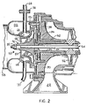
- Figure 2 is a partial longitudinal cross-section of the turbine expander of Figure 1;
- Figure 3 is a simplified schematic view of an alternate form of the present invention; and
- Figure 4 is another simplified schematic view of yet a further form of the present invention.
- Figure 1 illustrates a
system 10 for conditioning a working fluid, the system shown being an environmental control system as may be utilized in aircraft. Thesystem 10 includes a fluid flow path leading from aninlet duct 12 ultimately to anoutlet duct 14 from which the conditioned airflow is directed to a point of use within the aircraft. Control valve means in the form of a flow control or pressure control valve andshutoff device 16 is interposed in theinlet duct 12 for adjusting the rate of flow of working fluid delivered through afirst duct 18 toward the heat pass side of a primary orfirst heat exchanger 20. Theheat exchanger 20 acts as a heat sink having a cool path side carrying a flow of cooling air. This cooling air may be ambient air delivered through acooling passage 22 from aninlet 24 to anoutlet 26. - After extraction of a certain amount of heat from the working fluid, it is directed out of the
heat exchanger 20 through asecond duct 28 to the inlet of arotary compressor 30. From therotary compressor 30, the compressed working fluid is delivered through athird duct 32 into the heat pass side of asecondary heat exchanger 34 which is also disposed in thecooling duct 22 in heat exchange relationship with the cooling air therethrough. From thesecondary heat exchanger 34 the working fluid is passed through areheater heat exchanger 36 and afourth duct 38 to the inlet of acondenser heat exchanger 40. From the exhaust of theheat exchanger 40, the working fluid is directed through aduct 42 toward a water extractor ortrap 44. Condensed moisture is removed from the working fluid in thewater trap 44, and the excess water may be conveniently expelled through a duct 45 into thecooling passage 22. Exhaust of working fluid from thewater trap 44 is directed through a duct 46 into the cooling side of thereheater heat exchanger 36 for slight reheating of the demoisturized working fluid. From thereheater 36 the working fluid then passes through a duct 48 to a toroidally shapedinlet duct 50 of a turbine expander 52. - The
turbine expander 52 is connected via adrive shaft 54 to drive therotary compressor 30. Conveniently, acentral fan 56 is also mounted upon theshaft 54 within thecooling duct 22 to develop the cooling airflow through theduct 22 for use in extracting heat from the working fluid in both the primary andsecondary heat exchangers - Patent Publication No. EP-A-0 147 987 is related to such an arrangement.
- While passing through the turbine expander 52 the working fluid is rapidly expanded and therefore cooled and thereafter exhausted through a
duct 58 towards the cool side of thecondenser heat exchanger 50. Exhausting fromheat exchanger 40, the working fluid then passes through theoutlet duct 14 to a point of desired use. - For temperature control, a bypass passage 60, for relatively warm airflow, extends from the
first duct 18 at a point downstream of thecontrol valve 16 to an annular passage 62 surrounding theduct 58, and communicating with the latter immediately upstream of the entrance to thecondenser heat exchanger 40. In this way relatively warm air from thefirst duct 18 is intermixed with the working fluid. In a conventional manner the relatively warm airflow through the bypass 60 is controlled via atemperature control valve 64 having anautomatic control 65 associated therewith. - Additionally, a
system 10 incorporates a bypass fluid flow path including aduct 66 extending from theinlet duct 12, at a location upstream ofcontrol valve 16, to an anti-icing plenum orchamber 68 disposed adjacent theturbine expander 52. This bypass flow path extends onward from theanti-icing plenum 68 through asecond duct 70 which communicates with the fluid flow path at a location downstream of thecontrol valve 16. In the embodiment illustrated in Figure 1 thesecond duct 70 communicates with thefirst duct 18 at a location just upstream of theprimary heat exchanger 20. Disposed in thebypass passage 66 is afixed flow restrictor 72 schematically illustrated in Figure 1. The relative size of thebypass passage 66 and/or thefixed flow restrictor 72 is such that the nominal flow to thebypass 66 is of the order of 10% or less of the major working fluid flow passing across thecontrol valve 16 through the primary fluid flow path of the system. It will be noted that the conventionally controlledvalve 16 also has acontrol apparatus 74 associated therewith for actuating thecontrol valve 16 variably to restrict fluid flow therethrough and, ultimately, completely to shutoff fluid flow through the flow path. - One embodiment of the
rotary turbine expander 52 is illustrated in detail in Figure 2. More particularly, the rotary turbine expander 52 includes a radial inflow turbine wheel generally designated by thenumeral 76, having acentral hub portion 78 and a plurality ofblades 80 extending radially therefrom. The radialinflow turbine wheel 76 is driven by the working fluid received from itsinlet 82 to rotate theshaft 54. In the embodiment illustrated theshaft 54 includes aninternal shaft portion 84 and anexternal shaft portion 86. Secured by a nut 88, theradial turbine wheel 76 is frictionally held to drive theouter shaft portion 86 of the turbine wheel upon which is also mounted thecentral fan 56. Not illustrated in Figure 2 is thecompressor wheel 30 secured to the opposite ends of theshaft portions fan 56 on the shaft. - As illustrated in Figure 2, the associated
housing structure 90 defines the coolingpath 22 through which the cooling ambient airflow is induced by thecentral fan 56. Thehousing structure 90 associated with theturbine expander 52 carries compliant, multi-leafed, foiljournal air bearings 92 and a thrust foil bearing 94 which rotatably support theshaft 54 and therotating turbine expander 52. Being air bearings, thefoil bearings pickup 96 in thecompressor inlet 82 via aninternal duct 98 for delivery to thethrust bearing 94 andjournal bearings 92. - The
first bypass duct 66 extends inwardly to theanti-icing plenum 68 which is annular in configuration and substantially surrounds theblades 80 of theturbine wheel 76. An annular shroud wall 100 is disposed closely adjacent theblades 80 of theturbine wheel 76 and in heat exchanger relationship with theanti-icing plenum 68 which surrounds it. The anti-icing flow delivered from thebypass passage 66 across the fixedflow restrictor 72 to theanti-icing chamber 68 acts to warm the annular shroud wall 100 to prevent formation of ice adjacent theblades 80 of theturbine expander 52. - In operation of the system illustrated in Figures 1 and 2, relatively warm working fluid is delivered from the
inlet passage 12 to be throttled across thecontrol valve 16 for subsequent passage through the fluid flow path and ultimate delivery to theoutlet 14 to a point of use. The pressure differential developed across thecontrol valve 16 due to the throttling of working fluid therethrough induces a fluid flow through thebypass passage 66, across the restrictor 72 into theanti-icing plenum chamber 68. The anti-icing fluid flow to theplenum 68 exhausts through thepassage 70 back to theinlet duct 18 at a location downstream ofcontrol valve 16 just upstream of theprimary heat exchanger 20. In this manner the present invention utilizes a parasitic power loss, in the form of a pressure differential developed across thecontrol valve 16, to drive anti-icing flow of working fluid to theplenum 68. - The
plenum 68 acts to maintain the shroud wall 100 at a relatively warm temperature such that ice may not form at this location in the fluid flow path. It has been found in high performance fluid conditioning systems of the type described, that the actual temperature adjacent the turbine expander, and particularly at the blades, may reach temperatures of -24 degrees to -34 degrees C. In the absence of anti-icing techniques, such low temperatures may create formation of ice at the shroud wall 100. This can be highly deleterious to the operation of the system due to the very high rotational speed of the rotary turbine expander 52 (100,000 rpm or higher). In particular, such ice, and contact therewith by the turbine blades, imposes serious side loads which can destroy thebearings - Due to the configuration and arrangement of the
anti-icing bypass passages control valve 16 determines the magnitude of the bypass airflow directed through theanti-icing chamber 68. It has been found that the primary conditions which are most conducive to ice formation correspond to the operation of the fluid conditioning system when thevalve 16 is substantially throttling fluid flow therethrough and developing a substantial pressure differential thereacross. Accordingly, the present invention utilizes the pressure differential existing across thecontrol shutoff valve 16 to control the magnitude of the anti-icing airflow. In this manner the present invention provides an anti-icing flow which is controlled automatically in volume in relation to the critical operating parameters of the overall system in order to minimize parasitic power loss generated by the anti-icing airflow, yet without introduction of additional complexity in the control and operation of the system. - More particularly, in the design of the overall
fluid conditioning system 10, the heat exchangers must be sized to produce maximum performance of the system which occurs when maximum flow is being permitted across thecontrol valve 16 to thefirst duct 18. This occurs, of course, whenshutoff valve 16 is minimally restricting fluid flow therethrough. As a result, during throttling condition of thecontrol valve 16, which reduces the volume of fluid flow through the conditioning system, the various heat exchangers essentially become oversized, relative to the rate of warm airflow therethrough, such that extremely cold conditions can develop at different locations in the fluid flow path. Thus, the present invention, which develops substantial anti-icing flow only in a condition where substantial throttling is being developed by thecontrol valve 16, automatically minimizes the anti-icing airflow to that required by the system, and only when required by the system. - While in the embodiment of Figures 1 and 2 the location at which the anti-icing airflow is placed in heat exchange relationship with the primary fluid flow path is adjacent the turbine expander, it will be recognised that the present invention may be utilized to provide anti-icing at other locations in the fluid flow path where icing may occur. For example, the present invention may be utilized to direct an anti-icing flow to the inlet of the
condenser heat exchanger 40 where icing conditions might occur. - Figure 3 illustrates another form of the invention, and in this illustration several of the components are eliminatgd for purposes of simplification. Illustrated in Figure 3 is the
inlet duct 12,control valve 16,first duct 18,primary heat exchanger 20,second duct 28,compressor 30,third duct 32,secondary heat exchanger 34,fourth duct 38,turbine expander 52, andoutlet duct 14. Also, in Figure 3 is illustrated the temperature control bypass duct 60 and its associatedvalve 64. In the arrangement of Figure 3 thefirst bypass duct 66 along with the fixedflow restrictor 72 are illustrated for delivering the anti-icing airflow to theanti-icing chamber 68, along with the return or second duct means 70 for carrying the anti-icing airflow exhausted fromchamber 68. - In contrast to the Figure 1 arrangement, the embodiment illustrated in Figure 3 shows that the
second duct 70 may communicate with the primary fluid flow path at a location downstream of theprimary heat exchanger 20, in thesecond duct 28. This arrangement provides greater pressure differential for driving the anti-icing airflow through theanti-icing chamber 68. Additionally, as illustrated in Figure 3, the present invention may incorporate a flowcontrol shutoff valve 102 in thebypass passage 66. Thevalve 102 may be operationally related to thecontrol valve 16, as illustrated by the dashedline 104, such that, when thecontrol valve 16 is moved to a fully closed position, to shutoff any flow to the fluid conditioning system, theshutoff valve 102 may also be moved to a fully closed position, also to close the anti-icing flow, so that no parasitic flow, and therefore power losses, occur in the fluid conditioning system in the shutoff condition. - Figure 4 illustrates a further embodiment of the system and shows a simplified schematic, somewhat similar to Figure 3. Again, similar reference numerals identify like elements in the Figure 1 embodiment.
- In place of the fixed
flow restrictor 72 as shown in embodiments of the Figures 1 and 3, the embodiment illustrated in Figure 4 includes a relatively low pressure relief valve, schematically illustrated at 106. Thisrelief valve 106 acts normally to close fluid flow through thebypass passage 66 to theanti-icing chamber 68, in the absence of a pressure differential across theshutoff valve 16 below a predetermined magnitude. When the pressure differential across theshutoff valve 16 increases to a level above a predetermined magnitude (normally predetermined by the pretension of a spring 108), therelief valve 106 opens fully to permit anti-icing airflow therethrough. The arrangement of Figure 4 therefore provides automatic shutoff flow control through the anti-icing passage as provided by theshutoff valve 102 in Figure 3, and further provides that anti-icing flow occurs only when thecontrol valve 16 is throttling to a substantial, predetermined magnitude. - From the foregoing it will be apparent that the present invention provides an improved system for conditioning fluid in a fluid flow passage which includes the steps of directing the working fluid through a restriction in the form of the
control valve 16 which controls the flow and develops a pressure differential thereacross. Subsequently the working fluid is cooled downstream of thecontrol valve 16 via aheat exchanger 20, and is then further cooled by expansion at arotary turbine expander 52. The cooling accomplished by the heat exchanger and the turbine expander are capable of inducing ice formation at a location in the fluid path such as at theturbine expander 52. To inhibit formation of ice, the system according to one or more aspects of the present invention further includes the step of directing a parallel anti-icing flow of working fluid from the flow path at a location upstream of thecontrol valve 16 into heat exchange relationship with the shroud wall 100 at the location where icing may occur. The present invention contemplates utilizing the pressure differential across thecontrol valve 16 to induce and control the parallel anti-icing flow, by assuring return of the anti-icing flow to the fluid flow path at a location downstream of thecontrol valve 16 but upstream of the turbine expander.
Claims (8)
Applications Claiming Priority (2)
| Application Number | Priority Date | Filing Date | Title |
|---|---|---|---|
| US06/678,629 US4580406A (en) | 1984-12-06 | 1984-12-06 | Environmental control system |
| US678629 | 1984-12-06 |
Publications (3)
| Publication Number | Publication Date |
|---|---|
| EP0184443A2 EP0184443A2 (en) | 1986-06-11 |
| EP0184443A3 EP0184443A3 (en) | 1986-08-20 |
| EP0184443B1 true EP0184443B1 (en) | 1990-04-11 |
Family
ID=24723607
Family Applications (1)
| Application Number | Title | Priority Date | Filing Date |
|---|---|---|---|
| EP85308837A Expired - Lifetime EP0184443B1 (en) | 1984-12-06 | 1985-12-04 | Environmental control system |
Country Status (4)
| Country | Link |
|---|---|
| US (1) | US4580406A (en) |
| EP (1) | EP0184443B1 (en) |
| JP (1) | JPS61139597A (en) |
| DE (1) | DE3577137D1 (en) |
Families Citing this family (28)
| Publication number | Priority date | Publication date | Assignee | Title |
|---|---|---|---|---|
| GB2241742B (en) * | 1988-03-23 | 1992-06-03 | Rolls Royce Plc | Minimising the effects of icing in the intakes of aerospace propulsors. |
| US4829775A (en) * | 1988-05-02 | 1989-05-16 | United Technologies Corporation | Filtered environmental control system |
| US4921408A (en) | 1988-11-28 | 1990-05-01 | Graco Inc. | Non-icing quiet air-operated pump |
| JPH02245401A (en) * | 1989-03-17 | 1990-10-01 | Nippon Gurei Kk | Antifreezing device for air motor |
| JP2586648B2 (en) * | 1989-06-29 | 1997-03-05 | 株式会社島津製作所 | Air conditioner for aircraft |
| US4963174A (en) * | 1989-12-12 | 1990-10-16 | Payne George K | Hybrid vapor cycle/air cycle environmental control system |
| EP0515575A1 (en) * | 1990-02-20 | 1992-12-02 | AlliedSignal Inc. | Fluid conditioning apparatus and system |
| US5214935A (en) * | 1990-02-20 | 1993-06-01 | Allied-Signal Inc. | Fluid conditioning apparatus and system |
| US5113670A (en) * | 1990-08-03 | 1992-05-19 | United Technologies Corporation | Bearing cooling arrangement for air cycle machine |
| US5086622A (en) * | 1990-08-17 | 1992-02-11 | United Technologies Corporation | Environmental control system condensing cycle |
| US5133194A (en) * | 1991-02-04 | 1992-07-28 | United Technologies Corporation | Air cycle machine and fan inlet/diffuser therefor |
| US5311749A (en) * | 1992-04-03 | 1994-05-17 | United Technologies Corporation | Turbine bypass working fluid admission |
| US5279130A (en) * | 1992-06-18 | 1994-01-18 | General Electric Company | Auxiliary refrigerated air system with anti-icing |
| JPH11101520A (en) * | 1997-09-29 | 1999-04-13 | Sharp Corp | Air cycle type air conditioner |
| TW390936B (en) * | 1997-12-20 | 2000-05-21 | Allied Signal Inc | Microturbine power generating system |
| US6672081B1 (en) | 2002-10-31 | 2004-01-06 | Visteoo Global Technologies, Inc. | System and method of preventing icing in an air cycle system |
| DE102006032979A1 (en) * | 2006-07-17 | 2008-01-24 | Liebherr-Aerospace Lindenberg Gmbh | An aircraft air conditioning system and method for operating an aircraft air conditioning system |
| JP4457138B2 (en) * | 2007-09-28 | 2010-04-28 | 株式会社日立製作所 | Compressor and heat pump system |
| US8333549B2 (en) * | 2008-06-17 | 2012-12-18 | Honeywell International Inc. | Air cycle machine turbine outlet heated diffuser |
| JP5343511B2 (en) * | 2008-10-30 | 2013-11-13 | 株式会社島津製作所 | Heat exchanger |
| US8560203B2 (en) * | 2010-07-30 | 2013-10-15 | Pratt & Whitney Canada Corp. | Aircraft engine control during icing of temperature probe |
| JP2012092994A (en) * | 2010-10-25 | 2012-05-17 | Shimadzu Corp | Air conditioning system |
| US8851835B2 (en) | 2010-12-21 | 2014-10-07 | Hamilton Sundstrand Corporation | Air cycle machine compressor diffuser |
| US8784053B2 (en) * | 2010-12-21 | 2014-07-22 | Hamilton Sundstrand Corporation | Fan shield and bearing housing for air cycle machine |
| US20140352348A1 (en) * | 2013-05-29 | 2014-12-04 | Hamilton Sundstrand Corporation | Heat exchanger bypass arrangement and valve assembly |
| CN113864054B (en) * | 2021-10-15 | 2026-03-27 | 珠海格力电器股份有限公司 | Wheel cover assembly, turbine assembly and air circulator |
| CN115126556B (en) * | 2022-07-05 | 2024-10-11 | 珠海格力电器股份有限公司 | Turbine structure and air cycle machine applying same |
| CN115680799B (en) * | 2022-09-30 | 2025-09-23 | 珠海格力电器股份有限公司 | Wheel cover assembly, expander and air cycle machine |
Citations (1)
| Publication number | Priority date | Publication date | Assignee | Title |
|---|---|---|---|---|
| US4127011A (en) * | 1976-05-18 | 1978-11-28 | Normalair-Garret (Holdings) Limited | Air cycle air conditioning systems |
Family Cites Families (30)
| Publication number | Priority date | Publication date | Assignee | Title |
|---|---|---|---|---|
| US2732125A (en) * | 1956-01-24 | Differential area compressor bleed control | ||
| US2469375A (en) * | 1945-09-24 | 1949-05-10 | Westinghouse Electric Corp | Deicing apparatus for compressors |
| US2648193A (en) * | 1951-04-10 | 1953-08-11 | Westinghouse Electric Corp | Anti-icing apparatus having means to control temperature and pressure of the heating gases |
| US2705866A (en) * | 1951-06-28 | 1955-04-12 | Holley Carburetor Co | De-icing for gas turbines |
| US2868483A (en) * | 1952-02-08 | 1959-01-13 | Rudolph E Krueger | Anti-icing control system |
| GB767176A (en) * | 1952-10-10 | 1957-01-30 | Rolls Royce | Improvements in or relating to gas turbine power plant arrangements |
| US2750737A (en) * | 1953-04-20 | 1956-06-19 | Leonard P Leigh | Deicing apparatus for jet engines |
| GB753194A (en) * | 1953-11-17 | 1956-07-18 | Garrett Corp | Air conditioning systems, particularly for aircraft |
| BE535079A (en) * | 1954-01-25 | |||
| US2965285A (en) * | 1955-10-10 | 1960-12-20 | Holley Carburetor Co | Compressor bleed control |
| US2929224A (en) * | 1955-12-23 | 1960-03-22 | Garrett Corp | Gas turbine compressor driven air conditioning system |
| GB915124A (en) * | 1958-01-25 | 1963-01-09 | Sir George Godfrey And Partner | Improvements in or relating to refrigeration systems |
| US3058305A (en) * | 1959-04-16 | 1962-10-16 | Jr Leonard P Leigh | Control device for aircraft deicing apparatus |
| GB889305A (en) * | 1959-11-26 | 1962-02-14 | Rolls Royce | Gas turbine engine |
| US3123283A (en) * | 1962-12-07 | 1964-03-03 | Anti-icing valve means | |
| GB973401A (en) * | 1963-08-30 | 1964-10-28 | Rolls Royce | Gas turbine engine |
| US3236499A (en) * | 1964-06-05 | 1966-02-22 | Dominion Eng Works Ltd | Differential pressure control of sealing fluid for rotary fluid machines |
| US3327932A (en) * | 1965-04-21 | 1967-06-27 | United Aircraft Corp | Compressor bleed control |
| US3355905A (en) * | 1966-08-19 | 1967-12-05 | Garrett Corp | Air conditioning system with means for preventing the formation of ice |
| GB1115968A (en) * | 1966-10-17 | 1968-06-06 | Rolls Royce | Device for controlling the bleed of air from a gas turbine engine compressor |
| US3587243A (en) * | 1969-05-29 | 1971-06-28 | Grumman Aerospace Corp | Precondensing regenerative air cycle system |
| US3586458A (en) * | 1969-09-16 | 1971-06-22 | Avco Corp | Bleed control actuator for gas turbine engine |
| GB1385881A (en) * | 1971-02-12 | 1975-03-05 | Hawker Siddeley Dynamics Ltd | Air conditioning systems |
| US3945759A (en) * | 1974-10-29 | 1976-03-23 | General Electric Company | Bleed air manifold |
| DE2728400C2 (en) * | 1977-06-24 | 1987-02-12 | Brown, Boveri & Cie Ag, 6800 Mannheim | Gas turbine |
| US4198830B1 (en) * | 1978-07-03 | 1995-04-18 | Garrett Corp | Fluid conditioning apparatus and system |
| US4352273A (en) * | 1979-05-22 | 1982-10-05 | The Garrett Corporation | Fluid conditioning apparatus and system |
| US4334411A (en) * | 1980-03-11 | 1982-06-15 | The Garrett Corporation | Unique air cycle refrigeration system |
| US4444018A (en) * | 1980-07-25 | 1984-04-24 | The Garrett Corporation | Heat pump systems for residential use |
| US4374469A (en) * | 1980-12-24 | 1983-02-22 | United Technologies Corporation | Variable capacity air cycle refrigeration system |
-
1984
- 1984-12-06 US US06/678,629 patent/US4580406A/en not_active Expired - Lifetime
-
1985
- 1985-09-25 JP JP60210353A patent/JPS61139597A/en active Granted
- 1985-12-04 DE DE8585308837T patent/DE3577137D1/en not_active Expired - Lifetime
- 1985-12-04 EP EP85308837A patent/EP0184443B1/en not_active Expired - Lifetime
Patent Citations (1)
| Publication number | Priority date | Publication date | Assignee | Title |
|---|---|---|---|---|
| US4127011A (en) * | 1976-05-18 | 1978-11-28 | Normalair-Garret (Holdings) Limited | Air cycle air conditioning systems |
Also Published As
| Publication number | Publication date |
|---|---|
| EP0184443A2 (en) | 1986-06-11 |
| JPS61139597A (en) | 1986-06-26 |
| DE3577137D1 (en) | 1990-05-17 |
| EP0184443A3 (en) | 1986-08-20 |
| JPH0356374B2 (en) | 1991-08-28 |
| US4580406A (en) | 1986-04-08 |
Similar Documents
| Publication | Publication Date | Title |
|---|---|---|
| US4580406A (en) | Environmental control system | |
| EP1642828B1 (en) | Ram fan system for an aircraft environmental control system | |
| EP0035909B1 (en) | Air conditioning system | |
| CA2044292C (en) | Environmental control system condensing cycle | |
| EP1305210B1 (en) | Environmental control system utilizing two air cycle machines | |
| EP2322430B1 (en) | Environmental control system | |
| EP1492704B1 (en) | Air conditioning system | |
| US5014518A (en) | ECS with advanced air cycle machine | |
| US6148622A (en) | Environmental control system no condenser high pressure water separation system | |
| US6151909A (en) | Two spool air cycle machine having concentric shafts | |
| EP0019492A2 (en) | Gas conditioning system, especially air conditioning system | |
| US5214935A (en) | Fluid conditioning apparatus and system | |
| US20030051492A1 (en) | Method and a device for a conditioning for an aircraft cabin | |
| JP2004245193A (en) | Air cycle air conditioner for aircraft | |
| EP4585879A2 (en) | Feature for subfreezing heat exchanger | |
| EP4342798B1 (en) | Low pressure air cycle | |
| US20250388327A1 (en) | Air conditioning and vapor cycle system | |
| EP4299444A1 (en) | Split regeneration environmental control system | |
| JPH0583825B2 (en) | ||
| Tourret et al. | Air‐conditioning for Aircraft Cabins: A General Examination of the Conditions at Altitude and the Installations Required for Meeting Them | |
| Herr | Pressurized Navajo Environmental System | |
| Erez et al. | DESIGN OF A RAM AIR DRIVEN REVERSE BOOTSTRAP AIRCYCLE FOR AIRCRAFT PODS |
Legal Events
| Date | Code | Title | Description |
|---|---|---|---|
| PUAI | Public reference made under article 153(3) epc to a published international application that has entered the european phase |
Free format text: ORIGINAL CODE: 0009012 |
|
| AK | Designated contracting states |
Kind code of ref document: A2 Designated state(s): DE FR GB IT |
|
| PUAL | Search report despatched |
Free format text: ORIGINAL CODE: 0009013 |
|
| AK | Designated contracting states |
Kind code of ref document: A3 Designated state(s): DE FR GB IT |
|
| 17P | Request for examination filed |
Effective date: 19870210 |
|
| 17Q | First examination report despatched |
Effective date: 19871110 |
|
| RAP1 | Party data changed (applicant data changed or rights of an application transferred) |
Owner name: ALLIED-SIGNAL INC. (A DELAWARE CORPORATION) |
|
| GRAA | (expected) grant |
Free format text: ORIGINAL CODE: 0009210 |
|
| ITF | It: translation for a ep patent filed | ||
| AK | Designated contracting states |
Kind code of ref document: B1 Designated state(s): DE FR GB IT |
|
| REF | Corresponds to: |
Ref document number: 3577137 Country of ref document: DE Date of ref document: 19900517 |
|
| ET | Fr: translation filed | ||
| ITTA | It: last paid annual fee | ||
| PLBE | No opposition filed within time limit |
Free format text: ORIGINAL CODE: 0009261 |
|
| STAA | Information on the status of an ep patent application or granted ep patent |
Free format text: STATUS: NO OPPOSITION FILED WITHIN TIME LIMIT |
|
| 26N | No opposition filed | ||
| PGFP | Annual fee paid to national office [announced via postgrant information from national office to epo] |
Ref country code: GB Payment date: 19911122 Year of fee payment: 7 |
|
| PGFP | Annual fee paid to national office [announced via postgrant information from national office to epo] |
Ref country code: FR Payment date: 19911209 Year of fee payment: 7 |
|
| PGFP | Annual fee paid to national office [announced via postgrant information from national office to epo] |
Ref country code: DE Payment date: 19920131 Year of fee payment: 7 |
|
| PG25 | Lapsed in a contracting state [announced via postgrant information from national office to epo] |
Ref country code: GB Effective date: 19921204 |
|
| GBPC | Gb: european patent ceased through non-payment of renewal fee |
Effective date: 19921204 |
|
| PG25 | Lapsed in a contracting state [announced via postgrant information from national office to epo] |
Ref country code: FR Effective date: 19930831 |
|
| PG25 | Lapsed in a contracting state [announced via postgrant information from national office to epo] |
Ref country code: DE Effective date: 19930901 |
|
| REG | Reference to a national code |
Ref country code: FR Ref legal event code: ST |