EP0184269A2 - Fiber optic probe and method for determining the size and/or concentration of materials in suspension - Google Patents
Fiber optic probe and method for determining the size and/or concentration of materials in suspension Download PDFInfo
- Publication number
- EP0184269A2 EP0184269A2 EP85202023A EP85202023A EP0184269A2 EP 0184269 A2 EP0184269 A2 EP 0184269A2 EP 85202023 A EP85202023 A EP 85202023A EP 85202023 A EP85202023 A EP 85202023A EP 0184269 A2 EP0184269 A2 EP 0184269A2
- Authority
- EP
- European Patent Office
- Prior art keywords
- light
- fibers
- window
- probe
- particles
- Prior art date
- Legal status (The legal status is an assumption and is not a legal conclusion. Google has not performed a legal analysis and makes no representation as to the accuracy of the status listed.)
- Granted
Links
Images


Classifications
-
- G—PHYSICS
- G01—MEASURING; TESTING
- G01N—INVESTIGATING OR ANALYSING MATERIALS BY DETERMINING THEIR CHEMICAL OR PHYSICAL PROPERTIES
- G01N21/00—Investigating or analysing materials by the use of optical means, i.e. using sub-millimetre waves, infrared, visible or ultraviolet light
- G01N21/84—Systems specially adapted for particular applications
- G01N21/85—Investigating moving fluids or granular solids
- G01N21/8507—Probe photometers, i.e. with optical measuring part dipped into fluid sample
-
- G—PHYSICS
- G01—MEASURING; TESTING
- G01N—INVESTIGATING OR ANALYSING MATERIALS BY DETERMINING THEIR CHEMICAL OR PHYSICAL PROPERTIES
- G01N15/00—Investigating characteristics of particles; Investigating permeability, pore-volume, or surface-area of porous materials
- G01N15/02—Investigating particle size or size distribution
- G01N15/0205—Investigating particle size or size distribution by optical means, e.g. by light scattering, diffraction, holography or imaging
- G01N15/0211—Investigating a scatter or diffraction pattern
-
- G—PHYSICS
- G01—MEASURING; TESTING
- G01N—INVESTIGATING OR ANALYSING MATERIALS BY DETERMINING THEIR CHEMICAL OR PHYSICAL PROPERTIES
- G01N21/00—Investigating or analysing materials by the use of optical means, i.e. using sub-millimetre waves, infrared, visible or ultraviolet light
- G01N21/17—Systems in which incident light is modified in accordance with the properties of the material investigated
- G01N21/47—Scattering, i.e. diffuse reflection
- G01N2021/4704—Angular selective
- G01N2021/4711—Multiangle measurement
- G01N2021/4719—Multiangle measurement using a optical fibre array
Definitions
- This invention relates to a fiber optic probe that is particularly useful for in-situ detection and measurement of the intensity of light scattered by particles suspended in a transparent or translucent fluid medium.
- This invention also relates to the in-situ measurement of the size and/or concentration of solid particles, immiscible liquid droplets, or gas bubbles in suspension in the fluid medium.
- a fiber optic probe constructed in accordance with the invention makes use of the phenomenon that light traversing a transparent or translucent fluid medium containing particles whose refractive index differs from that of the medium results in the scattering of some of the light. This effect is known as Tyndall scattering.
- the fraction of the light scattered per unit of light path length depends on the surface area of the particles, the refractive indices of the medium and the particles (or, if the particles are opaque, on the reflectivity of the particle surface), and upon the relative sizes of the particles with respect to the wavelength of the illuminating light.
- the scattered light fraction is substantially linear with the concentration, assuming the other factors to be relatively constant.
- both the illuminating light and the scattered light are attenuated by secondary scattering, resulting in non-linearity of the collected scattered light with concentration.
- a probe according to the invention employs one or more optical fibers for transmitting light from a source to a continuous phase reaction medium so as to illuminate a predetermined area or zone thereof.
- the probe also employs one or more optical fibers to collect light scattered by particles in the illuminated zone and transmit such collected light to a detector.
- the use of optical fibers enables the illuminating light source and the collected light detector to be located at safe distances from the medium being monitored.
- Both sets of fibers i.e., the illuminating light fibers and the scattered light collecting fibers, are enclosed in a single fluid tight probe housing having a transparent window at one end which confronts the medium to be examined.
- the material from which the housing is made is one which can withstand the heat and constituency of the medium so as to be capable of immersion in the medium itself and at any desired area and depth thereof.
- the optical fibers are so oriented to the longitudinal axis of the probe housing that the longitudinal axes of the illuminating light fibers intersect the longitudinal axes of the collected light fibers at a common point on the longitudinal axis of the housing. This arrangement provides an adequate zone of illumination and an adequate illuminated field of view.
- a fiber optic probe comprising a housing having a longitudinal axis; a transparent window closing one end of said housing and having inner and outer surfaces; and at least two elongate optical fibers entering one end of the housing and extending through the housing, said fibers having corresponding ends confronting and terminating at an inner surface of said window at an opposite end of said housing, said terminal ends of said fibers being radially spaced from the longitudinal axis of said housing and circumferentially spaced from one another, said fibers having imaginary cylinders extending along their longitudinal axis and converging toward one another in a direction toward an outer surface of said window and intersecting one another within a field of-view centered on the longitudinal axis of said housing.
- the invention also resides in a method for determining the size and concentration of moving, light reflective particles in suspension in a fluid medium, said method comprising the steps of
- a probe constructed in accordance with the embodiment of Figure 1 is generally designated by reference number 1 and comprises a hollow, cylindrical, elongate housing 2 formed of a metal or some other suitable material capable of immersion in a fluid medium that is to be monitored.
- the housing 2 has external threads 3 at one end thereof.
- Fitted into the threaded end of the housing 2 is a support 4 having a flange 5 which is seated on the free end of the housing.
- Adjacent the flange is a groove 6 in which is accommodated a sealing ring 7 so as to provide a fluid tight joint between the support and the interior of the housing.
- the support 4 also is provided with an annular groove 8 on which is seated another seal 9.
- a transparent window 10 Seated upon the support 4 and the annular seal 9 is a transparent window 10 of suitable thickness, such as 2 mm, and formed of a suitable material, such as glass, quartz, sapphire, and the like.
- the support 4 and the window 10 are maintained in an assembled relationship by means of a cap 11 having an internally threaded bore 12 in which the threaded end of the housing 2 is accommodated.
- the cap has a flange 13 which overlies and seats upon the marginal edge of the window 10.
- the opposite end of the housing 2 is exteriorly threaded as at 14 for accommodation in a correspondingly threaded skirt 15 of a cap 16.
- a suitable seal 17 is interposed between the end of the housing 2 and the cap 16.
- the cap 16 is provided with three axially extending openings 18 which are radially and circumferentially spaced at uniform distances about the longitudinal axis 19 of the housing 2.
- the circumferential spacing between each opening 18 is preferably 120° although it will be obvious that other spacings for the openings are practical.
- each of the openings 18 Extending through each of the openings 18 is an optical fiber 20 of preferably uniform diameter. Suitable seals 21 provide a fluid tight connection between the cap 16 and the fibers 20.
- the fibers extend through the housing and have corresponding ends fixed in openings 22 formed in the support 4.
- the openings 22 also are preferably radially and circumferentially spaced uniformly about the axis 19 of the housing, but unlike the openings 18, the axes of the openings 22 converge in a direction toward the adjacent end of the housing. The angle of convergence may vary, as will be explained.
- the fibers 20 extend through the openings 22 and abut the inner surface of the window 10.
- a thin coating 23 of an optical coupling gel or oil having a refractive index similar to that of the fibers and the window is interposed between the window and the confronting ends of the fibers to reduce reflection losses'at the fiber/window interface.
- At least one of the fibers 20 has its free end located in a position to receive light from a source and transmit such light through the window 10 to illuminate a zone of a fluid sample.
- the remaining fibers may be coupled to one or more light detectors as will be explained in more detail hereinafter.
- the longitudinal axes of all of the fibers 20 intersect one another and the longitudinal axis 19 of the probe 1 at a common point 24 which lies on the longitudinal axis of the probe beyond the outer surface of the window 10.
- the diameter of the illuminating fiber is such that a substantially cylindrical beam of light 25 passes through the window into the sample.
- the diameter of the collecting light fibers preferably corresponds to that of the illuminating fiber so that, when an imaginary cylinder along the extended axes of the light collecting fibers 25a intersect with the light beam 25, there is formed a field of view 26 having the configuration of two back-to-back cones. The significance of this will be explained hereinafter.
- Figure 3 discloses a probe la which corresponds to the probe 1 except that the probe la has a window 10a having a convex outer surface 10b and the flange 13a at the free end of the cap 11 is configured to accommodate and seat upon the concave surface.
- the greatest thickness of the window 10a is at the longitudinal axis 19 of the probe and may be about 3 mm in thickness.
- the support 4a of the latter has four openings 22a therein instead of three.
- the openings 22a are uniformly radially and circumferentially spaced about the longitudinal axis 19 of the probe la and the longitudinal axes of the fibers converge and intersect one another and the axis 19 at a common point 24a.
- the angle of convergence with respect to the axis 19 is about 20°.
- the intersection point 24a does not extend beyond the convex outer surface 10b of the window 10a, but instead coincides therewith.
- each of the openings 22a is one of the cptical fibers 20.
- Two diametrically opposed fibers are coupled to one or more light sources for transmitting light beams 25a through the window 10a into the sample, whereas the other two fibers are associated with one or more light detectors for transmitting thereto light scattered by particles in that zone of the sample adjacent the point 24a.
- the resulting field of view 26a at the intersection of the fiber axes and the housing axis is substantially conical in configuration with the base of the cone coinciding with the convex outer surface of the window 10a.
- the field of view 26a therefore, is less than the field of view 25 produced in the embodiment of Figure 1.
- the window 10a has a flat outer surface and a peripheral flange 27 which underlies a flange 13b at the free end of a cap llb. Between the flanges 13b and 27 is an annular seal 28.
- a support 4b is similar to the supports 4 and 4a and underlies the inner surface of the window 10b and is provided with openings 22b for either three or four optical fibers 20 whose longitudinal axes converge and intersect one another and the longitudinal axis 19b at a common point 24b located at the outer surface of the window lOb, as a consequence of which the field of view 26b is conical and has its base at the outer surface of the window.
- optical fibers which are to transmit light into the sample have those ends which are remote from the sample optically connected to a suitable light source 29 as shown in Figure 6.
- Such fiber or fibers hereinafter will be referred to as the illuminating fiber or fibers.
- the remote ends of the remaining fibers are connected to one or more suitable light detecting and intensity measuring devices 30 and 31, respectively.
- Such remaining fibers hereinafter will be referred to as the light collecting fibers.
- the light collecting fibers For convenience of illustration only one illuminating fiber and one light collecting fiber are shown in Figure 6.
- a suitable source of light is a light emitting diode (LED), a laser diode, a continuous wave (CW) gas laser, an incandescent lamp, and a spectral lamp.
- Suitable detectors 30 include photodiodes and photomultipliers.
- a suitable intensity measuring device 31 is a photometer.
- the preferred detection and measuring devices comprise a photodiode and a transimpendanceaemplifier the output from which is coupled to a suitable control computer 32 cr the like which is operable to control the process.
- a suitable source 29 of light is a Honeywell Model SPX 4689-04 GaAlAs light emitting diode (LED) which emits light at a wavelength of about 0.8 micron and this is suitable for use in suspensions of particles of about one micron or greater in diameter.
- the light source may be energized by a Hewlett-Packard Model 6181C DC power source.
- a suitable detector 30 is a Math Associates Model E-5100 silicon PIN photodiode.
- a suitable measuring device/amplifier 31 is a UDT model 101A amplifier manufactured by United Detector Technology.
- a suitable control/computer 32 is an Intel single board computer Model SBC-80/24.
- Each optical fiber may be a plastic clad silica fiber having a core diameter of 0.6 mm.
- a source of such fibers is Quartz Products Corporation.
- an optical filter 33 can be interposed between the collecting fiber end and the detector 30 so as to exclude from the latter light having wavelengths other than those emitted by the light source.
- the light source 29 may be a monochromatic CW gas laser, a laser diode, or a spectral lamp, and the filter 33, 29 may be a narrow band pass filter or a monochromator.
- the probe 1 may be inserted via conventional tube fittings into a vessel 34 containing the sample 35 to be examined for the presence of particles or the probe may be immersed in the medium at any desired location within the latter.
- particles are used herein, such term is intended to encompass all forms of materials present in discontinuous form in a reaction medium. Thus, the term “particles” is intended to apply to materials such as liquid droplets in a gas or in an immiscible liquid, gas bvbbles in a liquid, or solid particulate in a gas or liquid.
- the embodiment shown in Figure 1 is preferred for use in the monitoring of samples containing low concentrations of particles. This is because a sample containing a low concentration is less turbid than one having a greater concentration, as a consequence of which there is less obstruction to penetration to penetration of the sample by the illuminating light beam.
- the light beam 25 is capable of illuminating a relatively large volumn of the sample as compared to the probe design 43 e.g. Figure 3 or 5.
- the field of view 26 is determined by projecting the imaginary cylinder 25a of the light collecting fiber 20 beyond the outer surface of the window 10 so that it intersects the light beam 25. Any particles in the field of view 26 will reflect or scatter some of the light and some of the scattered light will be collected by the light collecting fiber and will be transmitted by the latter to the detector and intensity measuring devices.
- the probe la of Figure 3 or 4 is preferred.
- the light beams 25a emitted by the illuminating fibers have a relatively shallow penetration into the sample, but the field of view 26a commences at the exterior surface of the window, thereby enabling light scattered by particles in the field of view to be collected by the light collecting fibers.
- the sensitivity of probes constructed according to the invention is dependent upon (1) the amount of light conducted to the field of view, (2) the efficiency with which the light scattered by the particles in the sample is collected and transmitted to the detector, and (3) the efficiency with which light other than that scattered by the particles (extraneous light) is excluded.
- a major source of extraneous light results from reflection of the illuminating light at the interface between the sample and the window. Typically 10 -5 to 10 -2 Watts (W) of light are used to illuminate the sample. The reflection at the window-sample interface is typically about 0.1 to 1 percent, or 10 -4 to 10 -8 W, and varies with the refractive index of the sample.
- the scattere.d light collected from very low concentrations of particles may be as low as 10 -13 W. Accordingly it is necessary to exclude virtually all of the reflected light.
- the geometry of the probes disclosed herein has been selected to yield maximum exclusion of reflected light consistent with otherwise acceptable performance. This is accomplished by choosing the angle between the longitudinal axes of the fibers and the longitudinal axis of the probe, the radial spacing of the fibers from the longitudinal axis of the probe, the circumferential spacing between the fibers, and the window thickness so that light reflected from the window does not fall on any cf the collecting fiber ends. Typically, these factors are so selected that such reflected light falls either alcng the probe axis or on that side of the probe axis opposite the illuminating fiber and between adjacent collecting fibers. By positioning the illuminating fibers diametrically opposite one another, light reflected from one such fiber is least likely to fall on a light collecting fiber.
- the amount of light collected and transmitted by the collecting fibers is approximately proportional to (1) their total cross-sectional area (i.e., the product of the number of collecting fibers and the cross-sectional area of each), (2) the inverse of the square of the distance between the ends of the fibers and the intersection of their axes, and (3) the angle between the illuminating fiber(s) and the collecting fibers(s).
- the optimum angle was found experimentally to be between about 20° to 25° for particles with diameters between 0.2 and 200 microns, but angles between about 10° and 30° yielded sensitivities within about 30 percent of the maximum.
- a radial distance from the fiber to the longitudinal axis of the probe of two to three times the fiber diameter was found to yield satisfactory results for three and four fiber probes in which the angle between the longitudinal axes of the fibers and the longitudinal axis of the probe is between 10° and 25°.
- the choice of the circumferential spacing between the illuminating fibers and the collecting fibers also represents a compromise between sensitivity and extraneous light reflection, with relatively small spacing (less than 9C') yielding better extraneous light rejection, but poorer sensitivity than larger spacing (over 90°).
- a circumferential spacing of the fibers of from 60° to 120° performs well.
- the sensitivity is approximately proportional to the fiber diameter. This results from the fact that both the cross-sectional area of the fibers and the square of the distance to the intersection are proportional to the square of the fiber diameter, while the depth of field (i.e., the length of the region in which the fields of view of the illuminating fibers and the collecting fibers overlap) increases with the fiber diameter.
- Plastic clad silica fibers having a core diameter of from 200 to 600 microns are most suitable. The larger diameters (about 600 microns) perform slightly better and are easiest to handle and are thus preferred. Fibers with larger core diameters are more expensive however and require probes of a larger diameter, due to their large bending radii, and are thus less desirable.
- the diameter of the illuminating fibers may be identical to each other and to that of the collecting fibers.
- smaller fibers When used in conjunction with LEDs or extended light sources, such as incandescent lamps or spectral lamps, smaller fibers will generally transmit less light to the sample and larger fibers increase the extraneous light more than they increase the illumination of the region viewed by the collection fibers.
- fibers with core diameters smaller than those of the collection fibers are preferred because their use results in less extraneous light due to the smaller diameter of the reflection from the window sample interface. Further, the depth of field of the probe is reduced, due to the smaller diameter of the illuminating light beam, which results in increased dynamic range.
- Illuminating fibers with core diameters of from 100 to 300 microns perform well in conjunction with laser light sources and 600 micron diameter collecting fibers.
- the number of collecting fibers employed represents a compromise between sensitivity and expense.
- One collecting fiber is sufficent for most applications, but more are advantageous for applications requiring high sensitivity.
- One illuminating fiber is sufficient to collect the light from a light emitting diode, laser, or laser diode, whereas two or more are advantageous for collecting light from extended sources.
- Probes with more than the minimum number of fibers required for the measurement provide redundancy which is advantageous in case of fiber breakage.
- the present invention also relates to a method for measuring either the size or concentration, or both simultaneously, of particles, immiscible liquid droplets, or gas bubbles suspended in a fluid medium employing the apparatus hereinbefore described.
- particle(s) as used hereinafter in the description and claims means solid particulate material., gas bubbles, or liquid droplets.
- the measurements can be performed in-situ within closed reactors, pipes, or-other process equipment. It thus is suitable for process control applications.
- the method is applicable to suspensions which are stirred, agitated, or flowing, or in which the particles otherwise are set in motion as, for example, suspensions in which the particles are moving under " . the influence of gravity.
- the method comprises illuminating a zone of a fluid medium containing moving, light reflective particles with light of a constant intensity and collecting and measuring a portion of the light reflected by the particles.
- the average intensity and the variance of the intensity of the collected reflected light are computed.
- the size and concentration of the particles are determined by comparison of the computed values with values resulting from identical measurements of a like medium containing like particles of known size and concentrations.
- a fraction of the light is reflected.
- the fraction of the incident light reflected from an illuminated zone of fixed volume within the medium depends on the size and number of particles present in that zone and on the refractive indices of the particles and the medium. If the intensity of the, illuminating light is not constant throughout the illuminated zone, or if the efficiency of collection of the reflected light is not constant throughout, the intensity of the detected light (i,e., the collected, reflected light) from a particle will depend on the position of the particle within the zone. If the particles are in motion, rather than stationary, the number and positions of particles in the illuminated zone will vary with time, thereby resulting in random fluctuations in the intensity of the detected light. The magnitude of these fluctuations will depend on the size and number of particles present.
- the fraction of light reflected from each particle may be considered a constant.
- fluctuations in the intensity of the detected light will be due to the statistical variations in the number and positions of particles in the illuminated zone.
- the average (mean) intensity of the detected light (X) and the variance (V) of the intensity of the detected light are given by: where D is the particle diameter, C is the particle concentration, and A * and B * are quantities whose values depend on the refractive index or reflectivity of the particles, the intensity of the illuminating light, the size of the illuminated zone, and the geometry of the illuminating and light collecting optics.
- a * and B * thus are constants for a particular combination of particle material, suspending medium, and optical system.
- Equations 1 and 2 can be solved simultaneously for the concentration (C) and diameter (D) to yield: where A and B are constants which are related to A * and B * by the equations:
- the size and concentration of like particles of unknown size and concentration suspended in a like medium can be determined by measuring the mean and variance of the intensity of light reflected by the known and unknown sus- pensions, respectively, using the same measuring apparatus for both suspensions, and applying Equation 3 and Equation 4.
- Equation 3 is independent of the particle size and Equation 4 is independent of concentration, it is possible to determine either the size or the concentration independently.
- the determination of particle size in a medium does not necessarily require that the average concentration of the particles in the illuminated zone be the same as that of the entire medium. It is only necessary that the particles in that zone be representative. Thus, the invention is applicable to particle size determination in processes in which the particle concentration is not constant throughout the medium.
- Xi and Vi represent the average intensity and variance, respectively, of the dete-cted light from one sample
- Ci and Di represent the concem- tration and average particle sire of the particles in that suspension
- Xj, Vj, Cj, and Dj represent the same variables in a second suspension of the same material in the same medium
- the direction i.e., smaller or larger, and. the relative magnitude of changes in the concentration and of the average size of particles, in a single suspension, also can be determined by repeatedly measuring the average intensity and variance of the collected light and applying Equations 7 and 8.
- the size or concentration of the particles may not fall within the range for which Equation 1 and Equation 2 are valid.
- the relationships among the size, concentration, mean, and variance are complex and exact expressions relating the variables cannot easily be derived.
- multiple known suspensions, having particle sizes and concentrations throughout the ranges of interest may be employed to determine empirical relationships which will have the general form of nonlinear simultaneous equations. If the average intensity and variance of the detected light are monotonic functions of the average particle size and concentration throughout the range of interest unique values for the concentration and average particle size of an unknown suspension can be obtained by inserting the measured values of the average intensity and the variance of the detected light from the unknown samples into the empirical equation thus obtained.
- concentrations and average diameters of samples of polystyrene beads were determined by the following procedure:
- a plurality of samples of polystyrene beads of known size were suspended in an aqueous sodium chloride solution.
- the beads were set in motion by agitation of the suspensions.
- the intensity of the reflected light was measured ten thousand times at three millisecond intervals for each suspension and the average (mean) and variance of these measurements computed. This was done three times for each of the suspensions. Average values for the mean and variance of each suspension were then used to compute, by the method of least squares, the constants for the regression equations:
Abstract
Description
- This invention relates to a fiber optic probe that is particularly useful for in-situ detection and measurement of the intensity of light scattered by particles suspended in a transparent or translucent fluid medium. This invention also relates to the in-situ measurement of the size and/or concentration of solid particles, immiscible liquid droplets, or gas bubbles in suspension in the fluid medium.
- In the practice of many chemical processes proper control of the process requires detection of the presence of a suspended phase in the reaction medium and determination of its concentration, particle size, or both. An example of such a process is one in , which crystals are to be formed in a reaction liquid. Detection of the onset of crystallization usually is necessary to control the process in such manner as to yield crystals of the desired size and purity. Detection of the onset of crystallization currently is accomplished by visual monitoring of the reaction medium, detection of the exotherm resulting from the heat of crystallization, or detection of an increase of the turbidity of the reaction medium as a result of the presence therein of-crystals. These known methods often lack sufficient sensitivity and dynamic range for proper process control.
- Numerous other methods exist for measuring the size and concentration of solid particles in suspension, but nearly all require removal of a sample of the suspension for examination and thus are not generally applicable to the measurement of liquid droplets or gas bubbles. These known methods also are unsuitable for the measurement of solid pac- ticles in those.instances in which the size and/or concentration undergoes changes unless the cause of the changes can be terminated abruptly on removal of the sample from the suspension.
- A fiber optic probe constructed in accordance with the invention makes use of the phenomenon that light traversing a transparent or translucent fluid medium containing particles whose refractive index differs from that of the medium results in the scattering of some of the light. This effect is known as Tyndall scattering. The fraction of the light scattered per unit of light path length depends on the surface area of the particles, the refractive indices of the medium and the particles (or, if the particles are opaque, on the reflectivity of the particle surface), and upon the relative sizes of the particles with respect to the wavelength of the illuminating light. At relatively low particle concentrations, the scattered light fraction is substantially linear with the concentration, assuming the other factors to be relatively constant. At relatively high concentrations, however, both the illuminating light and the scattered light are attenuated by secondary scattering, resulting in non-linearity of the collected scattered light with concentration.
- A probe according to the invention employs one or more optical fibers for transmitting light from a source to a continuous phase reaction medium so as to illuminate a predetermined area or zone thereof. The probe also employs one or more optical fibers to collect light scattered by particles in the illuminated zone and transmit such collected light to a detector. The use of optical fibers enables the illuminating light source and the collected light detector to be located at safe distances from the medium being monitored.
- Both sets of fibers, i.e., the illuminating light fibers and the scattered light collecting fibers, are enclosed in a single fluid tight probe housing having a transparent window at one end which confronts the medium to be examined. The material from which the housing is made is one which can withstand the heat and constituency of the medium so as to be capable of immersion in the medium itself and at any desired area and depth thereof. The optical fibers are so oriented to the longitudinal axis of the probe housing that the longitudinal axes of the illuminating light fibers intersect the longitudinal axes of the collected light fibers at a common point on the longitudinal axis of the housing. This arrangement provides an adequate zone of illumination and an adequate illuminated field of view.
- More particularly, the invention resides in a fiber optic probe comprising a housing having a longitudinal axis; a transparent window closing one end of said housing and having inner and outer surfaces; and at least two elongate optical fibers entering one end of the housing and extending through the housing, said fibers having corresponding ends confronting and terminating at an inner surface of said window at an opposite end of said housing, said terminal ends of said fibers being radially spaced from the longitudinal axis of said housing and circumferentially spaced from one another, said fibers having imaginary cylinders extending along their longitudinal axis and converging toward one another in a direction toward an outer surface of said window and intersecting one another within a field of-view centered on the longitudinal axis of said housing.
- The invention also resides in a method for determining the size and concentration of moving, light reflective particles in suspension in a fluid medium, said method comprising the steps of
- (a) illuminating a zone of said fluid medium with light capable of being transmitted by said fluid medium and reflected by said particles;
- (b) collecting reflected light;
- (c) measuring the average intensity and variations in intensity of the collected light; and
- (d) comparing the measured values of the average intensity and variations in intensity with corresponding values obtained by the application of steps (a), (b), and (c) to at least one other suspension of like medium containing like particles.
- Probes constructed in accordance with the invention are illustrated in the accompanying drawings, wherein:
- Figure 1 is a fragmentary sectional view of one embodiment and taken on the line 1-1 of Figure 2;
- Figure 2 is an end elevation view of the embodiment of Figure 1;
- Figure 3 is a view similar to Figure 1, but taken on the line 3-3 of Figure 4 and illustrating another embodiment;
- Figure 4 is an and elevational view of the embodiment of Figure 3;
- Figure 5 is a view similar to Figure 3, but illustrating a further embodiment; and
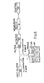
- Figure 6 is a diagrammatic illustration of the manner in which a probe according to the invention may be used.
- A probe constructed in accordance with the embodiment of Figure 1 is generally designated by reference number 1 and comprises a hollow, cylindrical,
elongate housing 2 formed of a metal or some other suitable material capable of immersion in a fluid medium that is to be monitored. Hereinafter the fluid medium sometimes will be referred to as the sample. Thehousing 2 hasexternal threads 3 at one end thereof. Fitted into the threaded end of thehousing 2 is asupport 4 having aflange 5 which is seated on the free end of the housing. Adjacent the flange is agroove 6 in which is accommodated a sealingring 7 so as to provide a fluid tight joint between the support and the interior of the housing. Thesupport 4 also is provided with anannular groove 8 on which is seated anotherseal 9. - Seated upon the
support 4 and theannular seal 9 is atransparent window 10 of suitable thickness, such as 2 mm, and formed of a suitable material, such as glass, quartz, sapphire, and the like. Thesupport 4 and thewindow 10 are maintained in an assembled relationship by means of a cap 11 having an internally threadedbore 12 in which the threaded end of thehousing 2 is accommodated. The cap has aflange 13 which overlies and seats upon the marginal edge of thewindow 10. - The opposite end of the
housing 2 is exteriorly threaded as at 14 for accommodation in a correspondingly threadedskirt 15 of acap 16. Asuitable seal 17 is interposed between the end of thehousing 2 and thecap 16. - The
cap 16 is provided with three axially extendingopenings 18 which are radially and circumferentially spaced at uniform distances about thelongitudinal axis 19 of thehousing 2. The circumferential spacing between each opening 18 is preferably 120° although it will be obvious that other spacings for the openings are practical. - Extending through each of the
openings 18 is anoptical fiber 20 of preferably uniform diameter.Suitable seals 21 provide a fluid tight connection between thecap 16 and thefibers 20. The fibers extend through the housing and have corresponding ends fixed inopenings 22 formed in thesupport 4. Theopenings 22 also are preferably radially and circumferentially spaced uniformly about theaxis 19 of the housing, but unlike theopenings 18, the axes of theopenings 22 converge in a direction toward the adjacent end of the housing. The angle of convergence may vary, as will be explained. Thefibers 20 extend through theopenings 22 and abut the inner surface of thewindow 10. Preferably, athin coating 23 of an optical coupling gel or oil having a refractive index similar to that of the fibers and the window is interposed between the window and the confronting ends of the fibers to reduce reflection losses'at the fiber/window interface. - At least one of the
fibers 20 has its free end located in a position to receive light from a source and transmit such light through thewindow 10 to illuminate a zone of a fluid sample. The remaining fibers may be coupled to one or more light detectors as will be explained in more detail hereinafter. For the time being, however, it is sufficient to state that the longitudinal axes of all of thefibers 20 intersect one another and thelongitudinal axis 19 of the probe 1 at acommon point 24 which lies on the longitudinal axis of the probe beyond the outer surface of thewindow 10. The diameter of the illuminating fiber is such that a substantially cylindrical beam oflight 25 passes through the window into the sample. The diameter of the collecting light fibers preferably corresponds to that of the illuminating fiber so that, when an imaginary cylinder along the extended axes of the light collectingfibers 25a intersect with thelight beam 25, there is formed a field ofview 26 having the configuration of two back-to-back cones. The significance of this will be explained hereinafter. - Figure 3 discloses a probe la which corresponds to the probe 1 except that the probe la has a window 10a having a convex outer surface 10b and the flange 13a at the free end of the cap 11 is configured to accommodate and seat upon the concave surface. The greatest thickness of the window 10a is at the
longitudinal axis 19 of the probe and may be about 3 mm in thickness. Another difference between the probes 1 and la is that the support 4a of the latter has four openings 22a therein instead of three. The openings 22a are uniformly radially and circumferentially spaced about thelongitudinal axis 19 of the probe la and the longitudinal axes of the fibers converge and intersect one another and theaxis 19 at a common point 24a. The angle of convergence with respect to theaxis 19 is about 20°. The intersection point 24a does not extend beyond the convex outer surface 10b of the window 10a, but instead coincides therewith. - Accommodated in each of the openings 22a is one of the
cptical fibers 20. Two diametrically opposed fibers are coupled to one or more light sources for transmittinglight beams 25a through the window 10a into the sample, whereas the other two fibers are associated with one or more light detectors for transmitting thereto light scattered by particles in that zone of the sample adjacent the point 24a. - As is apparent from Figure 3, the resulting field of view 26a at the intersection of the fiber axes and the housing axis is substantially conical in configuration with the base of the cone coinciding with the convex outer surface of the window 10a. The field of view 26a, therefore, is less than the field of
view 25 produced in the embodiment of Figure 1. - It is not necessary to use a window having a convex external surface to obtain a conical field of view like that indicated at 26a.
- In the embodiment shown in Figure 5, the window 10a has a flat outer surface and a
peripheral flange 27 which underlies a flange 13b at the free end of a cap llb. Between theflanges 13b and 27 is anannular seal 28. Asupport 4b is similar to thesupports 4 and 4a and underlies the inner surface of the window 10b and is provided with openings 22b for either three or fouroptical fibers 20 whose longitudinal axes converge and intersect one another and thelongitudinal axis 19b at acommon point 24b located at the outer surface of the window lOb, as a consequence of which the field ofview 26b is conical and has its base at the outer surface of the window. - In the application of any of the disclosed probes for use, optical fibers which are to transmit light into the sample have those ends which are remote from the sample optically connected to a suitable
light source 29 as shown in Figure 6. Such fiber or fibers hereinafter will be referred to as the illuminating fiber or fibers. The remote ends of the remaining fibers are connected to one or more suitable light detecting andintensity measuring devices - A suitable source of light is a light emitting diode (LED), a laser diode, a continuous wave (CW) gas laser, an incandescent lamp, and a spectral lamp.
Suitable detectors 30 include photodiodes and photomultipliers. A suitableintensity measuring device 31 is a photometer. The preferred detection and measuring devices comprise a photodiode and a transimpendanceaemplifier the output from which is coupled to asuitable control computer 32 cr the like which is operable to control the process. - More particularly, a
suitable source 29 of light is a Honeywell Model SPX 4689-04 GaAlAs light emitting diode (LED) which emits light at a wavelength of about 0.8 micron and this is suitable for use in suspensions of particles of about one micron or greater in diameter. The light source may be energized by a Hewlett-Packard Model 6181C DC power source. Asuitable detector 30 is a Math Associates Model E-5100 silicon PIN photodiode. A suitable measuring device/amplifier 31 is a UDT model 101A amplifier manufactured by United Detector Technology. A suitable control/computer 32 is an Intel single board computer Model SBC-80/24. Each optical fiber may be a plastic clad silica fiber having a core diameter of 0.6 mm. A source of such fibers is Quartz Products Corporation. - If light other than that intentionally transmitted to the sample is present, an
optical filter 33 can be interposed between the collecting fiber end and thedetector 30 so as to exclude from the latter light having wavelengths other than those emitted by the light source. - If a high degree of ambient light exclusion is required, the
light source 29 may be a monochromatic CW gas laser, a laser diode, or a spectral lamp, and thefilter - In use, the probe 1 may be inserted via conventional tube fittings into a
vessel 34 containing thesample 35 to be examined for the presence of particles or the probe may be immersed in the medium at any desired location within the latter. - Although the term "particles" is used herein, such term is intended to encompass all forms of materials present in discontinuous form in a reaction medium. Thus, the term "particles" is intended to apply to materials such as liquid droplets in a gas or in an immiscible liquid, gas bvbbles in a liquid, or solid particulate in a gas or liquid.
- The embodiment shown in Figure 1 is preferred for use in the monitoring of samples containing low concentrations of particles. This is because a sample containing a low concentration is less turbid than one having a greater concentration, as a consequence of which there is less obstruction to penetration to penetration of the sample by the illuminating light beam. Thus, the
light beam 25 is capable of illuminating a relatively large volumn of the sample as compared to the probe design 43 e.g. Figure 3 or 5. - The field of
view 26 is determined by projecting theimaginary cylinder 25a of thelight collecting fiber 20 beyond the outer surface of thewindow 10 so that it intersects thelight beam 25. Any particles in the field ofview 26 will reflect or scatter some of the light and some of the scattered light will be collected by the light collecting fiber and will be transmitted by the latter to the detector and intensity measuring devices. - In those instances in which the concentration of particles in the sample is relatively high, the probe la of Figure 3 or 4 is preferred. In such case the
light beams 25a emitted by the illuminating fibers have a relatively shallow penetration into the sample, but the field of view 26a commences at the exterior surface of the window, thereby enabling light scattered by particles in the field of view to be collected by the light collecting fibers. - The sensitivity of probes constructed according to the invention is dependent upon (1) the amount of light conducted to the field of view, (2) the efficiency with which the light scattered by the particles in the sample is collected and transmitted to the detector, and (3) the efficiency with which light other than that scattered by the particles (extraneous light) is excluded.
- For detection of very small concentrations of particles (in the parts per million to parts per billion range) exclusion of extraneous light is the most important consideration. A major source of extraneous light results from reflection of the illuminating light at the interface between the sample and the window. Typically 10-5 to 10-2 Watts (W) of light are used to illuminate the sample. The reflection at the window-sample interface is typically about 0.1 to 1 percent, or 10-4 to 10-8 W, and varies with the refractive index of the sample. The scattere.d light collected from very low concentrations of particles may be as low as 10-13 W. Accordingly it is necessary to exclude virtually all of the reflected light.
- The geometry of the probes disclosed herein has been selected to yield maximum exclusion of reflected light consistent with otherwise acceptable performance. This is accomplished by choosing the angle between the longitudinal axes of the fibers and the longitudinal axis of the probe, the radial spacing of the fibers from the longitudinal axis of the probe, the circumferential spacing between the fibers, and the window thickness so that light reflected from the window does not fall on any cf the collecting fiber ends. Typically, these factors are so selected that such reflected light falls either alcng the probe axis or on that side of the probe axis opposite the illuminating fiber and between adjacent collecting fibers. By positioning the illuminating fibers diametrically opposite one another, light reflected from one such fiber is least likely to fall on a light collecting fiber.
- The amount of light collected and transmitted by the collecting fibers is approximately proportional to (1) their total cross-sectional area (i.e., the product of the number of collecting fibers and the cross-sectional area of each), (2) the inverse of the square of the distance between the ends of the fibers and the intersection of their axes, and (3) the angle between the illuminating fiber(s) and the collecting fibers(s). The optimum angle was found experimentally to be between about 20° to 25° for particles with diameters between 0.2 and 200 microns, but angles between about 10° and 30° yielded sensitivities within about 30 percent of the maximum.
- A radial distance from the fiber to the longitudinal axis of the probe of two to three times the fiber diameter was found to yield satisfactory results for three and four fiber probes in which the angle between the longitudinal axes of the fibers and the longitudinal axis of the probe is between 10° and 25°. The choice of the circumferential spacing between the illuminating fibers and the collecting fibers also represents a compromise between sensitivity and extraneous light reflection, with relatively small spacing (less than 9C') yielding better extraneous light rejection, but poorer sensitivity than larger spacing (over 90°). In practice, a circumferential spacing of the fibers of from 60° to 120° performs well.
- Assuming that the circumferential spacing between the fibers and the ratio between the fiber diameter and the distance to the longitudinal axis of the probe is constant, the sensitivity is approximately proportional to the fiber diameter. This results from the fact that both the cross-sectional area of the fibers and the square of the distance to the intersection are proportional to the square of the fiber diameter, while the depth of field (i.e., the length of the region in which the fields of view of the illuminating fibers and the collecting fibers overlap) increases with the fiber diameter. Plastic clad silica fibers having a core diameter of from 200 to 600 microns are most suitable. The larger diameters (about 600 microns) perform slightly better and are easiest to handle and are thus preferred. Fibers with larger core diameters are more expensive however and require probes of a larger diameter, due to their large bending radii, and are thus less desirable.
- The diameter of the illuminating fibers may be identical to each other and to that of the collecting fibers. When used in conjunction with LEDs or extended light sources, such as incandescent lamps or spectral lamps, smaller fibers will generally transmit less light to the sample and larger fibers increase the extraneous light more than they increase the illumination of the region viewed by the collection fibers. When focused beams from CW lasers or laser diodes are used for illumination, fibers with core diameters smaller than those of the collection fibers are preferred because their use results in less extraneous light due to the smaller diameter of the reflection from the window sample interface. Further, the depth of field of the probe is reduced, due to the smaller diameter of the illuminating light beam, which results in increased dynamic range. Illuminating fibers with core diameters of from 100 to 300 microns perform well in conjunction with laser light sources and 600 micron diameter collecting fibers.
- The number of collecting fibers employed represents a compromise between sensitivity and expense. One collecting fiber is sufficent for most applications, but more are advantageous for applications requiring high sensitivity.
- One illuminating fiber is sufficient to collect the light from a light emitting diode, laser, or laser diode, whereas two or more are advantageous for collecting light from extended sources.
- Probes with more than the minimum number of fibers required for the measurement provide redundancy which is advantageous in case of fiber breakage.
- The present invention also relates to a method for measuring either the size or concentration, or both simultaneously, of particles, immiscible liquid droplets, or gas bubbles suspended in a fluid medium employing the apparatus hereinbefore described. For convenience, the term "particle(s)" as used hereinafter in the description and claims means solid particulate material., gas bubbles, or liquid droplets. The measurements can be performed in-situ within closed reactors, pipes, or-other process equipment. It thus is suitable for process control applications.
- The method is applicable to suspensions which are stirred, agitated, or flowing, or in which the particles otherwise are set in motion as, for example, suspensions in which the particles are moving under ". the influence of gravity.
- The method comprises illuminating a zone of a fluid medium containing moving, light reflective particles with light of a constant intensity and collecting and measuring a portion of the light reflected by the particles. The average intensity and the variance of the intensity of the collected reflected light are computed. The size and concentration of the particles are determined by comparison of the computed values with values resulting from identical measurements of a like medium containing like particles of known size and concentrations.
- Upon illumination of a zone of a transparent or translucent medium containing particles which are at least as large as the wavelength of the illuminating light, and which have a refractive index different from that of the medium, a fraction of the light is reflected. The fraction of the incident light reflected from an illuminated zone of fixed volume within the medium depends on the size and number of particles present in that zone and on the refractive indices of the particles and the medium. If the intensity of the, illuminating light is not constant throughout the illuminated zone, or if the efficiency of collection of the reflected light is not constant throughout, the intensity of the detected light (i,e., the collected, reflected light) from a particle will depend on the position of the particle within the zone. If the particles are in motion, rather than stationary, the number and positions of particles in the illuminated zone will vary with time, thereby resulting in random fluctuations in the intensity of the detected light. The magnitude of these fluctuations will depend on the size and number of particles present.
- In a case in which a dilute suspension of monosized particles is illuminated by light of constant intensity, the fraction of light reflected from each particle may be considered a constant. Thus, fluctuations in the intensity of the detected light will be due to the statistical variations in the number and positions of particles in the illuminated zone. In this instance, the average (mean) intensity of the detected light (X) and the variance (V) of the intensity of the detected light are given by:


-
Equations 1 and 2 can be solved simultaneously for the concentration (C) and diameter (D) to yield:


- If a suspension of particles of known size and concentration is obtained, the size and concentration of like particles of unknown size and concentration suspended in a like medium can be determined by measuring the mean and variance of the intensity of light reflected by the known and unknown sus- pensions, respectively, using the same measuring apparatus for both suspensions, and applying
Equation 3 andEquation 4. - Because
Equation 3 is independent of the particle size andEquation 4 is independent of concentration, it is possible to determine either the size or the concentration independently. - The determination of particle size in a medium does not necessarily require that the average concentration of the particles in the illuminated zone be the same as that of the entire medium. It is only necessary that the particles in that zone be representative. Thus, the invention is applicable to particle size determination in processes in which the particle concentration is not constant throughout the medium.
- If stable samples of known particle size and concentration are not available, as always is the case for gas bubbles, and often for liquid droplets, the calibration must be performed external to the process equipment. This sometimes can be accomplished by making light reflection measurements simultaneously with other measurements, such as photography-image analysis, which yields measures of the concentration and particle size.
- If a suspension of known particle size and concentration is not available, the relative sizes and concentrations of the particles in two suspensions of the same material in the same medium still can be determined. If Xi and Vi represent the average intensity and variance, respectively, of the dete-cted light from one sample, and Ci and Di represent the concem- tration and average particle sire of the particles in that suspension, and if Xj, Vj, Cj, and Dj represent the same variables in a second suspension of the same material in the same medium, then:
-


- The direction, i.e., smaller or larger, and. the relative magnitude of changes in the concentration and of the average size of particles, in a single suspension, also can be determined by repeatedly measuring the average intensity and variance of the collected light and applying
Equations - In some instances not all of the conditions stated above will be met. For example, in some industrial processes the size or concentration of the particles may not fall within the range for which Equation 1 and
Equation 2 are valid. In these cases the relationships among the size, concentration, mean, and variance are complex and exact expressions relating the variables cannot easily be derived. In such cases multiple known suspensions, having particle sizes and concentrations throughout the ranges of interest, may be employed to determine empirical relationships which will have the general form of nonlinear simultaneous equations. If the average intensity and variance of the detected light are monotonic functions of the average particle size and concentration throughout the range of interest unique values for the concentration and average particle size of an unknown suspension can be obtained by inserting the measured values of the average intensity and the variance of the detected light from the unknown samples into the empirical equation thus obtained. - The concentrations and average diameters of samples of polystyrene beads were determined by the following procedure:
- A plurality of samples of polystyrene beads of known size were suspended in an aqueous sodium chloride solution. Three different samples of beads, having average diameters of 0.222 mm, 0.458 mm, and 0.621 mm, respectively, were suspended in the solution .at concentrations of between 1.5 percent and 15 percent by volume. The beads were set in motion by agitation of the suspensions. Using the apparatus described above, the intensity of the reflected light was measured ten thousand times at three millisecond intervals for each suspension and the average (mean) and variance of these measurements computed. This was done three times for each of the suspensions. Average values for the mean and variance of each suspension were then used to compute, by the method of least squares, the constants for the regression equations:


- Twenty-seven suspensions then were prepared like the calibration samples, except that the diameters of the beads were not known. The values of the mean and variance of the intensity of the detected light from each suspension wece determined in a manner identical to that used in the calibration procedure. Measured values for the concentrations and average diameters then were obtained by inserting the detected mean and variance values into the
linear regression Equations 
- The disclosed embodiments are representative of presently preferred embodiments of the invention, but are intended to be illustrative rather definitive thereof.
Claims (22)
Applications Claiming Priority (4)
| Application Number | Priority Date | Filing Date | Title |
|---|---|---|---|
| US06/678,115 US4707134A (en) | 1984-12-04 | 1984-12-04 | Fiber optic probe |
| US678115 | 1984-12-04 | ||
| US75635985A | 1985-07-18 | 1985-07-18 | |
| US756359 | 1985-07-18 |
Publications (3)
| Publication Number | Publication Date |
|---|---|
| EP0184269A2 true EP0184269A2 (en) | 1986-06-11 |
| EP0184269A3 EP0184269A3 (en) | 1987-04-22 |
| EP0184269B1 EP0184269B1 (en) | 1990-08-08 |
Family
ID=27101958
Family Applications (1)
| Application Number | Title | Priority Date | Filing Date |
|---|---|---|---|
| EP19850202023 Expired - Lifetime EP0184269B1 (en) | 1984-12-04 | 1985-12-04 | Fiber optic probe and method for determining the size and/or concentration of materials in suspension |
Country Status (3)
| Country | Link |
|---|---|
| EP (1) | EP0184269B1 (en) |
| JP (1) | JPH0695070B2 (en) |
| DE (1) | DE3579124D1 (en) |
Cited By (11)
| Publication number | Priority date | Publication date | Assignee | Title |
|---|---|---|---|---|
| EP0335725A2 (en) * | 1988-04-01 | 1989-10-04 | Syntex (U.S.A.) Inc. | Apparatus and method for detection of fluorescence or light scatter |
| WO1990011508A1 (en) * | 1989-03-22 | 1990-10-04 | Kidde-Graviner Limited | Particulate detecting and optical coupling arrangements |
| GB2269012A (en) * | 1992-07-22 | 1994-01-26 | Martin Richard Holman | Colour sensor; Fetal blood oximeter |
| FR2722290A1 (en) * | 1994-07-07 | 1996-01-12 | Schneider Electric Sa | Optical detector for characteristics of particles in flow along wall |
| WO1997025607A1 (en) * | 1994-07-07 | 1997-07-17 | Schneider Electric S.A. | Optical device for detecting the characteristics of moving particles |
| US5864392A (en) * | 1995-12-15 | 1999-01-26 | Avl List Gmbh | Method for optically detecting gas bubbles moving in a coolant |
| EP0974045A1 (en) * | 1997-04-07 | 2000-01-26 | Laser Sensor Technology, Inc. | A system for acquiring an image of a multi-phase fluid by measuring backscattered light |
| WO2002040961A2 (en) * | 2000-11-15 | 2002-05-23 | Rusteck Ltd. | Optical detection of particles in a liquid medium |
| DE102009030691A1 (en) * | 2009-06-26 | 2010-12-30 | Fraunhofer-Gesellschaft zur Förderung der angewandten Forschung e.V. | Particle measuring head, particle measuring device and particle measuring method for measuring the particle load of fluids |
| EP2657688A1 (en) * | 2012-04-24 | 2013-10-30 | Pangang Group Panzhihua Iron & Steel Research Institute Co., Ltd. | Device for detecting hydrolysis of titanium oxysulfate in real-time and apparatus for controlling hydrolysis of titanium oxysulfate |
| CN117705665A (en) * | 2024-02-05 | 2024-03-15 | 中国科学技术大学 | Optical fiber probe, measuring device and measuring method for capturing concentration change of jet flow particles |
Families Citing this family (8)
| Publication number | Priority date | Publication date | Assignee | Title |
|---|---|---|---|---|
| US6842243B2 (en) * | 2001-12-10 | 2005-01-11 | Apprise Technologies, Inc. | Turbidity sensor |
| JP3932037B2 (en) * | 2002-12-20 | 2007-06-20 | 大阪瓦斯株式会社 | Dust measuring device |
| JP4570038B2 (en) * | 2005-03-18 | 2010-10-27 | 大阪瓦斯株式会社 | Dust measuring device |
| JP2007263876A (en) * | 2006-03-29 | 2007-10-11 | Miyazaki Prefecture | Calibration method in laser diffraction/scattering type particle size distribution measurement method, and measuring method of volume concentration of bubble in liquid |
| JP4663586B2 (en) * | 2006-06-08 | 2011-04-06 | Jfeアドバンテック株式会社 | Liquid concentration measuring device |
| CN103168225B (en) * | 2010-10-25 | 2015-11-25 | 阿库里赛托梅特斯公司 | For collecting system and the user interface of the data set in flow cytometer |
| JP5751532B2 (en) * | 2012-07-27 | 2015-07-22 | 株式会社タツノ | Oil type identification device |
| WO2015151240A1 (en) * | 2014-04-02 | 2015-10-08 | 株式会社日立製作所 | Analysis method and analysis device for detection of abnormal analyte |
Citations (7)
| Publication number | Priority date | Publication date | Assignee | Title |
|---|---|---|---|---|
| US3986778A (en) * | 1975-10-01 | 1976-10-19 | International Business Machines Corporation | Spectrophotometer sample holder |
| EP0017007A1 (en) * | 1979-03-31 | 1980-10-15 | Desitek Design und Vertrieb technischer Geräte GmbH | Measuring device for recording turbidity, especially of fluids |
| US4322164A (en) * | 1976-10-18 | 1982-03-30 | Oximetrix, Inc. | Sterilizable, disposable optical scattering reference medium and container assembly |
| JPS5766342A (en) * | 1980-04-28 | 1982-04-22 | Agency Of Ind Science & Technol | Optical measuring method for suspension particles in medium |
| JPS57190254A (en) * | 1981-05-20 | 1982-11-22 | Inoue Japax Res Inc | Probe for turbidity gauge |
| EP0098095A2 (en) * | 1982-06-22 | 1984-01-11 | Wyatt Technology Corporation | A process and apparatus for identifying or characterizing small particles |
| US4497577A (en) * | 1981-06-03 | 1985-02-05 | Hitachi, Ltd. | Steam wetness measuring apparatus |
-
1985
- 1985-12-04 DE DE8585202023T patent/DE3579124D1/en not_active Expired - Lifetime
- 1985-12-04 EP EP19850202023 patent/EP0184269B1/en not_active Expired - Lifetime
-
1991
- 1991-12-18 JP JP3361001A patent/JPH0695070B2/en not_active Expired - Lifetime
Patent Citations (7)
| Publication number | Priority date | Publication date | Assignee | Title |
|---|---|---|---|---|
| US3986778A (en) * | 1975-10-01 | 1976-10-19 | International Business Machines Corporation | Spectrophotometer sample holder |
| US4322164A (en) * | 1976-10-18 | 1982-03-30 | Oximetrix, Inc. | Sterilizable, disposable optical scattering reference medium and container assembly |
| EP0017007A1 (en) * | 1979-03-31 | 1980-10-15 | Desitek Design und Vertrieb technischer Geräte GmbH | Measuring device for recording turbidity, especially of fluids |
| JPS5766342A (en) * | 1980-04-28 | 1982-04-22 | Agency Of Ind Science & Technol | Optical measuring method for suspension particles in medium |
| JPS57190254A (en) * | 1981-05-20 | 1982-11-22 | Inoue Japax Res Inc | Probe for turbidity gauge |
| US4497577A (en) * | 1981-06-03 | 1985-02-05 | Hitachi, Ltd. | Steam wetness measuring apparatus |
| EP0098095A2 (en) * | 1982-06-22 | 1984-01-11 | Wyatt Technology Corporation | A process and apparatus for identifying or characterizing small particles |
Non-Patent Citations (2)
| Title |
|---|
| PATENT ABSTRACTS OF JAPAN, vol. 6, no. 145 (P-132)[1023], 4th August 1982; & JP - A - 57 66342 (KOGYO GIJUTSUIN) 22-04-1982 * |
| PATENT ABSTRACTS OF JAPAN, vol. 7, no. 38 (P-176)[1183], 16th February 1983; & JP - A - 57 190 254 (INOUE JAPAX KENKYUSHO K.K.) 22-11-1982 * |
Cited By (17)
| Publication number | Priority date | Publication date | Assignee | Title |
|---|---|---|---|---|
| EP0335725A2 (en) * | 1988-04-01 | 1989-10-04 | Syntex (U.S.A.) Inc. | Apparatus and method for detection of fluorescence or light scatter |
| EP0335725A3 (en) * | 1988-04-01 | 1991-03-27 | Syntex (U.S.A.) Inc. | Apparatus and method for detection of fluorescence or light scatter |
| WO1990011508A1 (en) * | 1989-03-22 | 1990-10-04 | Kidde-Graviner Limited | Particulate detecting and optical coupling arrangements |
| AU638981B2 (en) * | 1989-03-22 | 1993-07-15 | Kidde Ip Holdings Limited | Particulate detecting and optical coupling arrangements |
| GB2269012A (en) * | 1992-07-22 | 1994-01-26 | Martin Richard Holman | Colour sensor; Fetal blood oximeter |
| US5978073A (en) * | 1994-07-07 | 1999-11-02 | Schneider Electric Sa | Optical device for detecting the characteristics of moving particles |
| WO1997025607A1 (en) * | 1994-07-07 | 1997-07-17 | Schneider Electric S.A. | Optical device for detecting the characteristics of moving particles |
| FR2722290A1 (en) * | 1994-07-07 | 1996-01-12 | Schneider Electric Sa | Optical detector for characteristics of particles in flow along wall |
| US5864392A (en) * | 1995-12-15 | 1999-01-26 | Avl List Gmbh | Method for optically detecting gas bubbles moving in a coolant |
| EP0974045A1 (en) * | 1997-04-07 | 2000-01-26 | Laser Sensor Technology, Inc. | A system for acquiring an image of a multi-phase fluid by measuring backscattered light |
| EP0974045A4 (en) * | 1997-04-07 | 2002-11-27 | Laser Sensor Technology Inc | A system for acquiring an image of a multi-phase fluid by measuring backscattered light |
| WO2002040961A2 (en) * | 2000-11-15 | 2002-05-23 | Rusteck Ltd. | Optical detection of particles in a liquid medium |
| WO2002040961A3 (en) * | 2000-11-15 | 2003-09-04 | Rusteck Ltd | Optical detection of particles in a liquid medium |
| US7209231B2 (en) | 2000-11-15 | 2007-04-24 | Rusteck Ltd. | Optical detection of particles in a liquid medium |
| DE102009030691A1 (en) * | 2009-06-26 | 2010-12-30 | Fraunhofer-Gesellschaft zur Förderung der angewandten Forschung e.V. | Particle measuring head, particle measuring device and particle measuring method for measuring the particle load of fluids |
| EP2657688A1 (en) * | 2012-04-24 | 2013-10-30 | Pangang Group Panzhihua Iron & Steel Research Institute Co., Ltd. | Device for detecting hydrolysis of titanium oxysulfate in real-time and apparatus for controlling hydrolysis of titanium oxysulfate |
| CN117705665A (en) * | 2024-02-05 | 2024-03-15 | 中国科学技术大学 | Optical fiber probe, measuring device and measuring method for capturing concentration change of jet flow particles |
Also Published As
| Publication number | Publication date |
|---|---|
| EP0184269B1 (en) | 1990-08-08 |
| EP0184269A3 (en) | 1987-04-22 |
| JPH0695070B2 (en) | 1994-11-24 |
| JPH05256760A (en) | 1993-10-05 |
| DE3579124D1 (en) | 1990-09-13 |
Similar Documents
| Publication | Publication Date | Title |
|---|---|---|
| US4707134A (en) | Fiber optic probe | |
| EP0184269B1 (en) | Fiber optic probe and method for determining the size and/or concentration of materials in suspension | |
| JP2777536B2 (en) | Sample cell and sample cell monitor for scattered light measurement | |
| US6052184A (en) | Miniature, submersible, versatile, light scattering probe for absolute equilibrium and non-equilibrium characterization of macromolecular and colloidal solutions | |
| US5172182A (en) | Internal reflectance element with very small sample contacting surface | |
| US5181082A (en) | On-line titration using colorimetric end point detection | |
| US4753530A (en) | Analytical optical instruments | |
| US5241368A (en) | Fiber-optic probe for absorbance and turbidity measurement | |
| US4907884A (en) | Sample cell monitoring system | |
| EP0127418B1 (en) | Equipment for the measurement of fluorescence, turbidity, luminescence, or absorption | |
| JP2005536713A (en) | Apparatus and method for testing liquid properties | |
| US4827143A (en) | Monitor for particles of various materials | |
| US4659229A (en) | Readhead with reduced height sensitivity | |
| US4160914A (en) | Apparatus for measuring of particulate scattering in fluids | |
| EP0074976A1 (en) | Application of optical fibre probes | |
| US20040145742A1 (en) | Optical turbidimeter with a lens tube | |
| Maltsev et al. | Absolute real-time measurement of particle size distribution with the flying light-scattering indicatrix method | |
| US5015092A (en) | Sampling probe for optical analyzation of a sample | |
| US4755048A (en) | Optical analysis of impurity absorptions | |
| CA1256713A (en) | Method for determining the size and/or concentration of materials in suspension | |
| US20070070333A1 (en) | Light returning target for a photometer | |
| EP2997350B1 (en) | Turbidimeter | |
| WO2012007542A1 (en) | Optical measurement method and apparatus | |
| WO1999041589A1 (en) | Optical absorption measurement with light integrating cavity | |
| RU78320U1 (en) | LIQUID PARTICLE SIZE METER IN LIQUID |
Legal Events
| Date | Code | Title | Description |
|---|---|---|---|
| PUAI | Public reference made under article 153(3) epc to a published international application that has entered the european phase |
Free format text: ORIGINAL CODE: 0009012 |
|
| AK | Designated contracting states |
Kind code of ref document: A2 Designated state(s): DE FR GB NL |
|
| PUAL | Search report despatched |
Free format text: ORIGINAL CODE: 0009013 |
|
| AK | Designated contracting states |
Kind code of ref document: A3 Designated state(s): DE FR GB NL |
|
| 17P | Request for examination filed |
Effective date: 19871021 |
|
| 17Q | First examination report despatched |
Effective date: 19890116 |
|
| GRAA | (expected) grant |
Free format text: ORIGINAL CODE: 0009210 |
|
| AK | Designated contracting states |
Kind code of ref document: B1 Designated state(s): DE FR GB NL |
|
| REF | Corresponds to: |
Ref document number: 3579124 Country of ref document: DE Date of ref document: 19900913 |
|
| ET | Fr: translation filed | ||
| PLBI | Opposition filed |
Free format text: ORIGINAL CODE: 0009260 |
|
| 26 | Opposition filed |
Opponent name: METTLER-TOLEDO AG Effective date: 19910508 |
|
| NLR1 | Nl: opposition has been filed with the epo |
Opponent name: METTLER-TOLEDO AG |
|
| PLBN | Opposition rejected |
Free format text: ORIGINAL CODE: 0009273 |
|
| STAA | Information on the status of an ep patent application or granted ep patent |
Free format text: STATUS: OPPOSITION REJECTED |
|
| 27O | Opposition rejected |
Effective date: 19950323 |
|
| NLR2 | Nl: decision of opposition | ||
| REG | Reference to a national code |
Ref country code: GB Ref legal event code: IF02 |
|
| PGFP | Annual fee paid to national office [announced via postgrant information from national office to epo] |
Ref country code: FR Payment date: 20040825 Year of fee payment: 20 |
|
| PGFP | Annual fee paid to national office [announced via postgrant information from national office to epo] |
Ref country code: NL Payment date: 20040827 Year of fee payment: 20 |
|
| PGFP | Annual fee paid to national office [announced via postgrant information from national office to epo] |
Ref country code: GB Payment date: 20040923 Year of fee payment: 20 |
|
| PGFP | Annual fee paid to national office [announced via postgrant information from national office to epo] |
Ref country code: DE Payment date: 20041018 Year of fee payment: 20 |
|
| APAH | Appeal reference modified |
Free format text: ORIGINAL CODE: EPIDOSCREFNO |
|
| PG25 | Lapsed in a contracting state [announced via postgrant information from national office to epo] |
Ref country code: GB Free format text: LAPSE BECAUSE OF EXPIRATION OF PROTECTION Effective date: 20051203 |
|
| PG25 | Lapsed in a contracting state [announced via postgrant information from national office to epo] |
Ref country code: NL Free format text: LAPSE BECAUSE OF EXPIRATION OF PROTECTION Effective date: 20051204 |
|
| REG | Reference to a national code |
Ref country code: GB Ref legal event code: PE20 |
|
| NLV7 | Nl: ceased due to reaching the maximum lifetime of a patent |
Effective date: 20051204 |