EP0184217A2 - Low pressure arc discharge tube having increased voltage - Google Patents
Low pressure arc discharge tube having increased voltage Download PDFInfo
- Publication number
- EP0184217A2 EP0184217A2 EP85115532A EP85115532A EP0184217A2 EP 0184217 A2 EP0184217 A2 EP 0184217A2 EP 85115532 A EP85115532 A EP 85115532A EP 85115532 A EP85115532 A EP 85115532A EP 0184217 A2 EP0184217 A2 EP 0184217A2
- Authority
- EP
- European Patent Office
- Prior art keywords
- discharge tube
- low pressure
- arc discharge
- pressure arc
- envelope
- Prior art date
- Legal status (The legal status is an assumption and is not a legal conclusion. Google has not performed a legal analysis and makes no representation as to the accuracy of the status listed.)
- Granted
Links
Images
Classifications
-
- H—ELECTRICITY
- H01—ELECTRIC ELEMENTS
- H01J—ELECTRIC DISCHARGE TUBES OR DISCHARGE LAMPS
- H01J61/00—Gas-discharge or vapour-discharge lamps
- H01J61/02—Details
- H01J61/04—Electrodes; Screens; Shields
- H01J61/10—Shields, screens, or guides for influencing the discharge
- H01J61/103—Shields, screens or guides arranged to extend the discharge path
Definitions
- This invention relates to low pressure arc discharge tubes and more particularly to such tubes having an increased voltage drop thereacross.
- ballastless discharge lamps it is desirable to raise the voltage across the lamp to equal the line voltage (110 volts in the U.S.: 220 volts in Europe) in order to minimize other circuit losses.
- metal halide discharge lamps In low power, i.e. 40W, metal halide discharge lamps it is desirable to operate at about 50 volts across the lamps to maintain stability (approx. 50-60 volts across the ballast). This higher voltage can be obtained by raising the mercury pressure. However, this increases the probability of explosions. Therefore, it is desirable to raise the voltage without increasing the pressure.
- the voltage across an arc discharge tube can be increased by varying the operating parameters of the discharge tube, such as the pressure; the current; the cathode fall: etc. However, altering these parameters effects the performance or some other aspect of the discharge tube.
- a low pressure arc discharge tube having an envelope of elongate, substantially cylindrical shape and having an electrode located at each end of the envelope.
- the envelope encloses an inert starting gas and a quantity of mercury. Included within the envelope are structural means for raising the voltage across the arc tube.
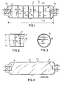
- FIG. 1 shows an arc discharge tube 10 according to a preferred embodiment of the invention.
- the arc discharge tube 10 includes an envelope 12 of substantially cylindrical shape which is generally made of light-transmitting soda-lime, lead, quartz or other suitable material.
- An electrode 14 is located within each of the two axially opposed end portions 12a of the envelope.
- the envelope 12 encloses an ionizable medium including a quantity of mercury and an inert starting gas, e.g. neon at a low pressure in the range of about 0.5 to 4 torr.
- Structural means 18 of quartz, glass, ceramic or other suitable electrically insulating material for raising the voltage across the arc discharge tube 10 are incorporated within envelope 12.
- structural means 18 comprise a plurality of axially spaced apart partitions 20 each having at least one aperture 22 therein. Each of the partitions extends across the envelope 12 substantially normal to the longitudinal axis 23 and has a thickness T.
- T has a dimension less than the electron energy relaxation distance d of the discharge tube.
- the electron energy relaxation distance is defined by the equation:
- Each of the partitions 20 contains at least one aperture 22 which constricts the arc within the tube and causes an increase in the voltage across the arc discharge tube.
- Aperture 22 having a diameter C can be located at the center of the partition 20 or eccentrically located in the partition as in FIGS. 1-3. Locating the aperture 22 remote from the center of the partition, and having the apertures 22 of adjacent partitions 20 positioned in non-alignment provides the added advantage of increasing the effective arc length of the tube. The maximum effective arc length is achieved if the apertures 22 are also located alternatingly about the longitudinal axis of the arc tube and if the apertures intersect a common plane passing through the longitudinal axis.
- the partitions 20 may be sealed hermetically to the interior surface of envelope 12. However, an hermetic seal is unnecessary if the total area between the perimeter of each partition and the interior surface of the envelope is less than the area of aperture 22.
- the forming of the end portions 12a and the sealing of the electrode 14 leadwires can be performed after the partitions 20 are installed.
- each partition 20 is inversely proportional to the size of the aperture 22.
- An increase in voltage can be achieved when the ratio of the internal diameter B of the envelope 12 to the aperture 22 diameter C is as small as approximately 1.1:1.
- the aperture 22 diameter C should be made small enough to achieve a ratio B:C of approximately 50:1.
- Voltage increases of from about 0.5 volts to about 20 volts per partition can be achieved depending on the ratio B:C.
- FIGS. 1-6 The invention will now be described more fully with reference to examples and to the drawings in FIGS. 1-6.
- Each arc discharge tube was constructed from quartz all having an envelope 12 wall thickness of about 1 mm, a length X equal to about 90 mm and an outside diameter of about 25 mm. Each arc tube contained a fill gas of 100 percent neon at a pressure of about 2.0 torr.
- the arc tube 10 of FIG. 1 was made with six apertured quartz partitions 20, each having a thickness T equal to about 1 mm.
- the partitions 20 were equally spaced apart from each other by about 10 mm.
- the distance from either electrode 14 to an adjacent partition 20 was also about 10 mm.
- Each of the six partitions 20 had an aperture 22 diameter C of about 0.5 mm. This results in a ratio B:C of 50:1.
- the apertures 22 were located alternating about the longitudinal axis of the arc tube 10. The distance D from the longitudinal asix to the midpoint of each aperture was about 2 mm.
- the apertures also intersect a common plane passing through the longitudinal axis of the arc tube (e.g., the plane of the drawing of FIG. 1).
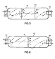
- FTG. 4 shows a reference or control tube 10' constructed without the apertured partitions.
- FIG. 5 shows an arc tube 10" according to another embodiment of the invention containing two apertured quartz partitions 24, each having a thickness T equal to about 1 mm.
- the two partitions were spaced apart from each other by about 25 mm.
- the distance from either electrode 14 to an adjacent" partition 24 was about 20 mm.
- the two partitions 24 had an aperture 26 having a diameter C of about 2 mm and located coaxially at about the midpoint of the partition.
- FIG. 6 shows an arc tube 101" made in accordance with yet another invention and having a single quartz partition 24 located at approximately the center of the tube.
- the partition 24 had a thickness T equal of about 1 mm.
- This partition 24 which was similar to those used in FIG. 5, had an aperture 26 with a diameter C of about 2 mm and was located coaxially at about the midpoint of the partition 24.
- the partition 24 of FIG. 6 was positioned at about the center of the arc tube envelope 12.
- Table 1 shows the electrical parameters obtained from the four above mentioned arc tubes.
- Arc tubes 10, 10" and 10" were made according to the invention while arc tube 10' denotes the reference control tube.
- a comparison of arc tube 10 with the reference arc tube 10 shows that at. an arc current of 1.0 amp, the voltage across the arc tube has increased by about 92 percent. This is a voltage increase per partition of 6 volts.
- a comparison of arc tubes 10" and 10"' shows an increase bf 11 volts per partition at. an arc current of 1.0 amp and an increase of 8 volts per partition at an arc current of 0.5 amp.
- the present invention is not limited to use in a glow discharge of mercury-inert gas without a phosphor layer.
- use of partitions according to the invention in a 14" T12 European fluorescent lamp could increase the voltage from 39 volts to 100 volts. This would cause the voltage across the ballast to drop from 180 volts to 120 volts and thereby reduce the ballast losses by 35%.
Landscapes
- Vessels And Coating Films For Discharge Lamps (AREA)
- Discharge Lamps And Accessories Thereof (AREA)
Abstract
Description
- This application discloses subject matter related to that in Attorney's Docket Nos. 23.353: 24.938: 24.955: 83-1-091: and 84-1-117. filed concurrently herewith, and assigned to the Assignee of this Application. but does not claim the inventions claimed in such related Applications.
- This invention relates to low pressure arc discharge tubes and more particularly to such tubes having an increased voltage drop thereacross.
- It is often desirable to have a higher voltage drop across an arc discharge tube. For example, in ballastless discharge lamps it is desirable to raise the voltage across the lamp to equal the line voltage (110 volts in the U.S.: 220 volts in Europe) in order to minimize other circuit losses.
- In low power, i.e. 40W, metal halide discharge lamps it is desirable to operate at about 50 volts across the lamps to maintain stability (approx. 50-60 volts across the ballast). This higher voltage can be obtained by raising the mercury pressure. However, this increases the probability of explosions. Therefore, it is desirable to raise the voltage without increasing the pressure.
- It is known in the art that the voltage across an arc discharge tube can be increased by varying the operating parameters of the discharge tube, such as the pressure; the current; the cathode fall: etc. However, altering these parameters effects the performance or some other aspect of the discharge tube.
- It is therefore, an object of this invention to obviate the disadvantages of the prior art.
- It is another object of the invention to provide an arc discharge tube having an increased voltage drop thereacross.
- These objects are accomplished, in one aspect of the invention, by the provision of a low pressure arc discharge tube having an envelope of elongate, substantially cylindrical shape and having an electrode located at each end of the envelope. The envelope encloses an inert starting gas and a quantity of mercury. Included within the envelope are structural means for raising the voltage across the arc tube.
- Incorporation of the last-mentioned structural means allows the arc tube to have increased voltage thereacross without changing any of the operational parameters such as the pressure, current, cathode fall, etc.
-
- . FIG. 1 is an elevational view, partly broken away. of an embodiment of the invention.
- FIG. 2 is a partial cross-sectional view of FIG. 1.
- FIG. 3 is a cross-sectional view as taken along the line 3-3 in FIG. 1.
- FIG. 4 is an elevational view of a prior-art type arc discharge tube used as a control or reference in testing embodiments of the invention.
- FIG. 5 is an elevational view of another embodiment of the invention: and
- FIG. 6 is an elevational view of yet another embodiment of the invention.
- For a better understanding of the present invention, together with other and further objects, advantages, and capabilities thereof, reference is made to the following disclosure and appended claims taken in conjunction with the above-described drawings.
- Referring now to the drawings with greater particularity, FIG. 1 shows an
arc discharge tube 10 according to a preferred embodiment of the invention. Thearc discharge tube 10 includes anenvelope 12 of substantially cylindrical shape which is generally made of light-transmitting soda-lime, lead, quartz or other suitable material. Anelectrode 14 is located within each of the two axially opposed end portions 12a of the envelope. Theenvelope 12 encloses an ionizable medium including a quantity of mercury and an inert starting gas, e.g. neon at a low pressure in the range of about 0.5 to 4 torr. Structural means 18 of quartz, glass, ceramic or other suitable electrically insulating material for raising the voltage across thearc discharge tube 10 are incorporated withinenvelope 12. As shown in FIGS. 1-3structural means 18 comprise a plurality of axially spaced apartpartitions 20 each having at least oneaperture 22 therein. Each of the partitions extends across theenvelope 12 substantially normal to thelongitudinal axis 23 and has a thickness T. - For best results T has a dimension less than the electron energy relaxation distance d of the discharge tube. The electron energy relaxation distance is defined by the equation:

- PHg is the mercury number density in the vapor
- PR is the rare gas number density
- Qin Hg is the total inelastic scattering cross-section for the electrons by Hg.
- Qin R is the total inelastic scattering cross-section for the electrons by gas
- OHg is the total scattering cross-section for electrons by Hg.
- Q is the total scattering cross-section for electrons by gas.
- Each of the
partitions 20 contains at least oneaperture 22 which constricts the arc within the tube and causes an increase in the voltage across the arc discharge tube.Aperture 22 having a diameter C can be located at the center of thepartition 20 or eccentrically located in the partition as in FIGS. 1-3. Locating theaperture 22 remote from the center of the partition, and having theapertures 22 ofadjacent partitions 20 positioned in non-alignment provides the added advantage of increasing the effective arc length of the tube. The maximum effective arc length is achieved if theapertures 22 are also located alternatingly about the longitudinal axis of the arc tube and if the apertures intersect a common plane passing through the longitudinal axis. - The
partitions 20 may be sealed hermetically to the interior surface ofenvelope 12. However, an hermetic seal is unnecessary if the total area between the perimeter of each partition and the interior surface of the envelope is less than the area ofaperture 22. The forming of the end portions 12a and the sealing of theelectrode 14 leadwires can be performed after thepartitions 20 are installed. - The voltage developed by each
partition 20 is inversely proportional to the size of theaperture 22. An increase in voltage can be achieved when the ratio of the internal diameter B of theenvelope 12 to theaperture 22 diameter C is as small as approximately 1.1:1. For maximum voltage increase, theaperture 22 diameter C should be made small enough to achieve a ratio B:C of approximately 50:1. Voltage increases of from about 0.5 volts to about 20 volts per partition can be achieved depending on the ratio B:C. - The invention will now be described more fully with reference to examples and to the drawings in FIGS. 1-6.
- Four arc discharge tubes were constructed from quartz all having an
envelope 12 wall thickness of about 1 mm, a length X equal to about 90 mm and an outside diameter of about 25 mm. Each arc tube contained a fill gas of 100 percent neon at a pressure of about 2.0 torr. - The
arc tube 10 of FIG. 1 was made with six aperturedquartz partitions 20, each having a thickness T equal to about 1 mm. Thepartitions 20 were equally spaced apart from each other by about 10 mm. The distance from eitherelectrode 14 to anadjacent partition 20 was also about 10 mm. - Each of the six
partitions 20 had anaperture 22 diameter C of about 0.5 mm. This results in a ratio B:C of 50:1. Theapertures 22 were located alternating about the longitudinal axis of thearc tube 10. The distance D from the longitudinal asix to the midpoint of each aperture was about 2 mm. The apertures also intersect a common plane passing through the longitudinal axis of the arc tube (e.g., the plane of the drawing of FIG. 1). - FTG. 4 shows a reference or control tube 10' constructed without the apertured partitions.
- FIG. 5 shows an
arc tube 10" according to another embodiment of the invention containing twoapertured quartz partitions 24, each having a thickness T equal to about 1 mm. The two partitions were spaced apart from each other by about 25 mm. The distance from eitherelectrode 14 to an adjacent"partition 24 was about 20 mm. The twopartitions 24 had anaperture 26 having a diameter C of about 2 mm and located coaxially at about the midpoint of the partition. - FIG. 6 shows an arc tube 101" made in accordance with yet another invention and having a
single quartz partition 24 located at approximately the center of the tube. Thepartition 24 had a thickness T equal of about 1 mm. - This
partition 24, which was similar to those used in FIG. 5, had anaperture 26 with a diameter C of about 2 mm and was located coaxially at about the midpoint of thepartition 24. Thepartition 24 of FIG. 6 was positioned at about the center of thearc tube envelope 12. - Table 1 shows the electrical parameters obtained from the four above mentioned arc tubes.
Arc tubes 
- A comparison of
arc tube 10 with thereference arc tube 10 shows that at. an arc current of 1.0 amp, the voltage across the arc tube has increased by about 92 percent. This is a voltage increase per partition of 6 volts. - A comparison of
arc tubes 10" and 10"' shows an increase bf 11 volts per partition at. an arc current of 1.0 amp and an increase of 8 volts per partition at an arc current of 0.5 amp. - 11. is possible t.o obtain larger than 11 volts per partition as shown in Table I by further reduction in the fill gas pressure. As the pressure is reduced, the discharge at the area around the aperture in the partition becomes reddish which is characteristic of neon excitation. This was observed when about 16 volts was generated around the aperture. For aperture diameters less than about. 0.1 mm, the voltage generated can be even greater.
- The present invention is not limited to use in a glow discharge of mercury-inert gas without a phosphor layer. For example, use of partitions according to the invention in a 14" T12 European fluorescent lamp could increase the voltage from 39 volts to 100 volts. This would cause the voltage across the ballast to drop from 180 volts to 120 volts and thereby reduce the ballast losses by 35%.
- While there have been shown what are at present considered to be preferred embodiments of the invention, it will be apparent to those skilled in the art that various changes and modifications can be made herein without departing from the scope of the invention as defined by the appended claims.
Claims (13)
Applications Claiming Priority (2)
| Application Number | Priority Date | Filing Date | Title |
|---|---|---|---|
| US67895884A | 1984-12-06 | 1984-12-06 | |
| US678958 | 1984-12-06 |
Publications (3)
| Publication Number | Publication Date |
|---|---|
| EP0184217A2 true EP0184217A2 (en) | 1986-06-11 |
| EP0184217A3 EP0184217A3 (en) | 1988-11-02 |
| EP0184217B1 EP0184217B1 (en) | 1991-06-05 |
Family
ID=24725033
Family Applications (1)
| Application Number | Title | Priority Date | Filing Date |
|---|---|---|---|
| EP19850115532 Expired EP0184217B1 (en) | 1984-12-06 | 1985-12-06 | Low pressure arc discharge tube having increased voltage |
Country Status (4)
| Country | Link |
|---|---|
| EP (1) | EP0184217B1 (en) |
| JP (1) | JPS61135041A (en) |
| CA (1) | CA1255738A (en) |
| DE (1) | DE3583120D1 (en) |
Cited By (3)
| Publication number | Priority date | Publication date | Assignee | Title |
|---|---|---|---|---|
| DE19547813A1 (en) * | 1995-12-20 | 1997-06-26 | Heraeus Noblelight Gmbh | Electrodeless discharge lamp with diaphragm body |
| US5814951A (en) * | 1995-12-20 | 1998-09-29 | Heraeus Noblelight Gmbh | Low-pressure discharge lamp containing a partition therein |
| WO2015165843A1 (en) * | 2014-04-29 | 2015-11-05 | LAZAREV, Nikolai | Light source |
Families Citing this family (1)
| Publication number | Priority date | Publication date | Assignee | Title |
|---|---|---|---|---|
| EP1437760B1 (en) * | 2001-09-28 | 2013-05-22 | Hamamatsu Photonics K.K. | Gas discharge tube |
Citations (2)
| Publication number | Priority date | Publication date | Assignee | Title |
|---|---|---|---|---|
| DE912243C (en) * | 1950-08-11 | 1954-05-28 | Dr Franz Skaupy | Fluorescent tube |
| FR1162139A (en) * | 1954-12-14 | 1958-09-09 | Thomson Houston Comp Francaise | Crush-resistant enclosures for low-pressure or incandescent tubular discharge lamps and improved efficiency discharge lamps |
-
1985
- 1985-12-05 JP JP27264785A patent/JPS61135041A/en active Pending
- 1985-12-05 CA CA000496969A patent/CA1255738A/en not_active Expired
- 1985-12-06 EP EP19850115532 patent/EP0184217B1/en not_active Expired
- 1985-12-06 DE DE8585115532T patent/DE3583120D1/en not_active Expired - Fee Related
Patent Citations (2)
| Publication number | Priority date | Publication date | Assignee | Title |
|---|---|---|---|---|
| DE912243C (en) * | 1950-08-11 | 1954-05-28 | Dr Franz Skaupy | Fluorescent tube |
| FR1162139A (en) * | 1954-12-14 | 1958-09-09 | Thomson Houston Comp Francaise | Crush-resistant enclosures for low-pressure or incandescent tubular discharge lamps and improved efficiency discharge lamps |
Cited By (5)
| Publication number | Priority date | Publication date | Assignee | Title |
|---|---|---|---|---|
| DE19547813A1 (en) * | 1995-12-20 | 1997-06-26 | Heraeus Noblelight Gmbh | Electrodeless discharge lamp with diaphragm body |
| US5801495A (en) * | 1995-12-20 | 1998-09-01 | Heraeus Noblelight Gmbh | Low-pressure discharge lamp containing partitions therein |
| US5814951A (en) * | 1995-12-20 | 1998-09-29 | Heraeus Noblelight Gmbh | Low-pressure discharge lamp containing a partition therein |
| EP0780882A3 (en) * | 1995-12-20 | 1999-02-24 | Heraeus Noblelight GmbH | Electrodeless discharge lamp with a diaphragm member |
| WO2015165843A1 (en) * | 2014-04-29 | 2015-11-05 | LAZAREV, Nikolai | Light source |
Also Published As
| Publication number | Publication date |
|---|---|
| EP0184217A3 (en) | 1988-11-02 |
| CA1255738A (en) | 1989-06-13 |
| EP0184217B1 (en) | 1991-06-05 |
| JPS61135041A (en) | 1986-06-23 |
| DE3583120D1 (en) | 1991-07-11 |
Similar Documents
| Publication | Publication Date | Title |
|---|---|---|
| EP0332263B1 (en) | Electrodeless low-pressure discharge lamp | |
| US5325024A (en) | Light source including parallel driven low pressure RF fluorescent lamps | |
| CA1303117C (en) | Arc discharge lamp with ultraviolet radiation starting source | |
| JP2004528695A (en) | Ceramic metal halide lamp | |
| JPH11513189A (en) | High pressure series arc discharge lamp structure with simplified starting aid | |
| CN1258379A (en) | Unit comprising short-arc discharge lamp with starting antenna | |
| US4527097A (en) | High-pressure sodium discharge lamp | |
| WO2002091428A2 (en) | Ceramic metal halide lamps | |
| EP0184215B1 (en) | Low pressure arc discharge tube | |
| US4884007A (en) | Low pressure arc discharge tube having increased voltage | |
| US4445069A (en) | Low-pressure discharge lamp | |
| EP0184217B1 (en) | Low pressure arc discharge tube having increased voltage | |
| EP0156384A2 (en) | Electrode alignment and capsule design for single-ended low wattage metal halide lamps | |
| US4962334A (en) | Glow discharge lamp having wire anode | |
| JP2000311660A (en) | Gas discharge lamp | |
| US6507151B1 (en) | Gas discharge lamp with a capactive excitation structure | |
| EP0145072B1 (en) | Method of operating a high-pressure discharge lamp | |
| US4356428A (en) | Lighting system | |
| US3849699A (en) | Single base, self-igniting fluorescent lamp | |
| WO1991008581A1 (en) | Glow discharge lamp | |
| US4935664A (en) | Diffuse discharge lamp | |
| GB2089114A (en) | A non-linear discharge lamp with a starting aid | |
| US4358701A (en) | Discharge lamps having internal starting aid capacitively coupled to one of the electrodes | |
| KR20030041704A (en) | External electrode fluorescent lamp | |
| EP0184214A2 (en) | Compact fluorescent lamp assembly |
Legal Events
| Date | Code | Title | Description |
|---|---|---|---|
| PUAI | Public reference made under article 153(3) epc to a published international application that has entered the european phase |
Free format text: ORIGINAL CODE: 0009012 |
|
| 17P | Request for examination filed |
Effective date: 19851206 |
|
| AK | Designated contracting states |
Kind code of ref document: A2 Designated state(s): BE DE FR GB NL |
|
| PUAL | Search report despatched |
Free format text: ORIGINAL CODE: 0009013 |
|
| AK | Designated contracting states |
Kind code of ref document: A3 Designated state(s): BE DE FR GB NL |
|
| 17Q | First examination report despatched |
Effective date: 19890821 |
|
| GRAA | (expected) grant |
Free format text: ORIGINAL CODE: 0009210 |
|
| AK | Designated contracting states |
Kind code of ref document: B1 Designated state(s): BE DE FR GB NL |
|
| ET | Fr: translation filed | ||
| REF | Corresponds to: |
Ref document number: 3583120 Country of ref document: DE Date of ref document: 19910711 |
|
| PG25 | Lapsed in a contracting state [announced via postgrant information from national office to epo] |
Ref country code: GB Effective date: 19911206 |
|
| PG25 | Lapsed in a contracting state [announced via postgrant information from national office to epo] |
Ref country code: BE Effective date: 19911231 |
|
| PLBE | No opposition filed within time limit |
Free format text: ORIGINAL CODE: 0009261 |
|
| STAA | Information on the status of an ep patent application or granted ep patent |
Free format text: STATUS: NO OPPOSITION FILED WITHIN TIME LIMIT |
|
| 26N | No opposition filed | ||
| BERE | Be: lapsed |
Owner name: GTE PRODUCTS CORP. Effective date: 19911231 |
|
| PG25 | Lapsed in a contracting state [announced via postgrant information from national office to epo] |
Ref country code: NL Effective date: 19920701 |
|
| GBPC | Gb: european patent ceased through non-payment of renewal fee | ||
| NLV4 | Nl: lapsed or anulled due to non-payment of the annual fee | ||
| PG25 | Lapsed in a contracting state [announced via postgrant information from national office to epo] |
Ref country code: FR Effective date: 19920831 |
|
| PG25 | Lapsed in a contracting state [announced via postgrant information from national office to epo] |
Ref country code: DE Effective date: 19920901 |
|
| REG | Reference to a national code |
Ref country code: FR Ref legal event code: ST |