EP0332263B1 - Electrodeless low-pressure discharge lamp - Google Patents
Electrodeless low-pressure discharge lamp Download PDFInfo
- Publication number
- EP0332263B1 EP0332263B1 EP89200531A EP89200531A EP0332263B1 EP 0332263 B1 EP0332263 B1 EP 0332263B1 EP 89200531 A EP89200531 A EP 89200531A EP 89200531 A EP89200531 A EP 89200531A EP 0332263 B1 EP0332263 B1 EP 0332263B1
- Authority
- EP
- European Patent Office
- Prior art keywords
- winding
- lamp
- antennas
- pressure discharge
- discharge lamp
- Prior art date
- Legal status (The legal status is an assumption and is not a legal conclusion. Google has not performed a legal analysis and makes no representation as to the accuracy of the status listed.)
- Expired - Lifetime
Links
Images
Classifications
-
- H—ELECTRICITY
- H01—ELECTRIC ELEMENTS
- H01J—ELECTRIC DISCHARGE TUBES OR DISCHARGE LAMPS
- H01J65/00—Lamps without any electrode inside the vessel; Lamps with at least one main electrode outside the vessel
- H01J65/04—Lamps in which a gas filling is excited to luminesce by an external electromagnetic field or by external corpuscular radiation, e.g. for indicating plasma display panels
- H01J65/042—Lamps in which a gas filling is excited to luminesce by an external electromagnetic field or by external corpuscular radiation, e.g. for indicating plasma display panels by an external electromagnetic field
- H01J65/048—Lamps in which a gas filling is excited to luminesce by an external electromagnetic field or by external corpuscular radiation, e.g. for indicating plasma display panels by an external electromagnetic field the field being produced by using an excitation coil
Definitions
- the invention relates to an electrodeless low-pressure discharge lamp having a glass lamp vessel which is sealed in a gas-tight manner and which is filled with at least a metal vapour and a rare gas, said lamp having a first winding which is connected to a high-frequency electric power supply unit and which generates an electric discharge in the lamp vessel, one of the supply wires of the first winding being electrically connected to a supply wire of a second winding which extends at the area of the first winding and which has a free end, the potential gradient between the ends of the first winding being substantially equal to that of the second winding during operation.
- a lamp is known from Netherlands Patent Application No. 8401307 laid open to public inspection.
- This lamp formed as a high-frequency operated fluorescent electrodeless low-pressure mercury vapour discharge lamp having a bulb-shaped lamp vessel, is used, inter alia as an alternative for an incandescent lamp for general illumination purposes.
- the ends of the first winding are connected to a high-frequency oscillator power supply circuit, for example of a type as described in Netherlands Patent Application No. 8004175 laid open to public inspection.
- a high-frequency oscillator power supply circuit for example of a type as described in Netherlands Patent Application No. 8004175 laid open to public inspection.
- Such a circuit is comparatively simple and during operation of the lamp one of the supply wires of the winding is permanently at a zero potential level.
- Due to the presence of a second winding high-frequency electric interference currents occurring during lamp operation in the conductors of the power supply mains are reduced to an acceptable level.
- the number of turns of the two windings is preferably equal in order to obtain the same potential gradient (this is the potential decrease per unit length of the winding, measured in the direction of its longitudinal axis).
- the presence of the second winding compensates for the electric interference currents, generated by the first winding, on the power supply mains.
- This known lamp obviates the use of a transparent conducting layer on the inner wall of the lamp vessel, which layer is connected to one of the supply wires of the power supply mains for suppressing the said interference currents.
- Providing the layer and connecting the said mains conductor is complicated, time-consuming and costly.
- such a lamp is therefore characterized in that ignition antennas are secured to the free end of the second winding and to one end of the first winding.
- a lamp according to the invention has a low ignition voltage as compared with the said known lamp. It has been found in a practical embodiment that the ignition voltage is a factor of 2 to 3 lower. The electric field generated by the antennas hardly contributes to interference currents on the power supply mains.
- the two antennas are coupled to the windings in such a way that during lamp operation a relatvely large potential difference is present between the antennas.
- the antenna which is secured to the free end of the second winding has a potential which is in phase opposition with the signal from the high-frequency power supply source.
- the other antenna (which is secured to the first winding) is in phase with this power supply source.
- One of the supply wires of the first winding is substantially constantly at a zero potential.
- United States Patent 4,253,047 describes an electrodeless low-pressure discharge lamp in which an annular core of magnetic material is present in the lamp vessel.
- the annular core has a single winding whose ends are connected to a highfrequency oscillator circuit.
- the lamp vessel comprises two ignition electrodes located on either side of this core, which electrodes are connected to the winding. These electrodes are provided with emissive material.
- the drawback of such a construction is that a comparatively large voltage difference is generated between the electrodes which are located at a short distance from each other, with the result that emissive material easily enters the lamp vessel. This will readily lead to blackening of the wall.
- additional means are required to stabilize the discharge between the starter electrodes. It is neither evident from the Patent in how far the interference requirements are satisfied.
- the windings and the antennas in the lamp according to the invention are located, for example, without a core in the gaseous atmosphere of the lamp vessel, or they surround a rod-shaped core of synthetic material or ceramic material.
- a rod-shaped core of a magnetic material is present and it is surrounded by the two windings which are present in a tubular indentation in the wall of the lamp vessel.
- the antennas are also present in the said indentation and extend on either side of the rod-shaped core parallel to the longitudinal axis of said core.
- the antennas are, for example wire-shaped or strip-shaped extending parallel to the wall of the tubular indentation.
- the advantage of this embodiment is that special lead-through constructions in the wall of the lamp vessel for the antennas are avoided.
- Such a lamp can be manufactured in a simple manner, ensuring ready ignition when starting the lamp (also in a situation with a low power consumption, i.e. in the case of a dimmed state).
- the lamp vessel is sealed in a gas-tight manner by means of a glass sealing member provided with a tubular indentation for a rod-shaped core (which indentation is located in the longitudinal direction of the lamp in a practical embodiment) and a conical wall portion.
- a glass sealing member provided with a tubular indentation for a rod-shaped core (which indentation is located in the longitudinal direction of the lamp in a practical embodiment) and a conical wall portion.
- the antennas extend at least on the outer wall of the conical wall portion and are located substantially opposite to each other.
- This embodiment is notably advantageous if there is little space to accommodate the said antennas between the rod-shaped core with the two windings and the juxtaposed wall of the tubular indentation. Therefore, the advantage of this embodiment is that its manufacture may be less complicated.
- the lamp of Fig. 1 has a glass bulb-shaped lamp vessel 1 which is sealed in a gas-tight manner by means of a glass sealing member 2. This seal is realized by means of a sealed connection between the conical wall portion 22 of member 2 and the lamp vessel 1.
- the lamp vessel is filled with mercury and a rare gas such as argon.
- a luminescent layer 3 is present on the inner wall of the lamp vessel.
- the sealing member 2 has a tubular indentation 4 accommodating a rod-shaped core 5 of ferrite.
- a first winding 6 surrounds this core and its ends 7 and 8 are connected to a high-frequency oscillator power supply 9 shown diagrammatically (as described in said Netherlands Patent Application 8004175 laid open to public inspection) which is present in a thin-walled synthetic material housing 10 connected at one end to the lamp vessel 1 and at the other end having the lamp cap 11 with which the lamp can be screwed into a holder for incandescent lamps.
- a high-frequency oscillator power supply 9 shown diagrammatically (as described in said Netherlands Patent Application 8004175 laid open to public inspection) which is present in a thin-walled synthetic material housing 10 connected at one end to the lamp vessel 1 and at the other end having the lamp cap 11 with which the lamp can be screwed into a holder for incandescent lamps.
- winding 6 During operation of the lamp an electric discharge is generated in the lamp vessel by means of winding 6 and the power supply 9. At one point the winding 6 is electrically connected to a second winding 12 (shown in a broken line) which has a free end 13 (see also Fig. 2).
- This second winding 12 has substantially the same number of turns as the first winding 6 and is wound in the same way.
- the two windings are electrically insulated from each other.
- the potential gradient between the ends of winding 6 is substantially equal to the potential gradient between the ends of winding 12.
- a wire-shaped antenna 14 is secured to the free end 13 of the second winding 12; this antenna is electrically insulated from the two windings 6 and 12 and it is stretched and extends substantially throughout the length of the two windings, whilst antenna 15 is secured to the end remote from 13.
- This antenna is also wire-shaped, stretched and electrically insulated from the two windings.
- the antennas 14 and 15 are located on either side of the rod 5.
- the length of antenna 15 corresponds to that of antenna 14.
- the antenna 15 is secured proximate the first turn of winding 6. This position is denoted by 16 in the Figure.
- the antennas are present in the space betweeen the windings and the wall of the tubular indentation 4.
- a potential difference having such a value that the lamp readily ignites and re-ignites is present between the antennas 14 and 15.
- the two antennas constitute the poles of a high-frequency electric field. The operation of the antennas will be further described with reference to Fig. 2.
- Fig. 2 shows diagrammatically the circuit of the two windings with the antennas coupled thereto in the lamp of Fig. 1.
- the output terminals of the high-frequency power supply oscillator are denoted by 17 and 18.
- the other reference numerals are the same as those in Fig. 1.
- a high-frequency power supply unit (not further shown) is connected between the terminals 17 and 18.
- Terminal 17 is continuously at substantially zero potential whilst the high-frequency oscillator voltage is applied to terminal 18. This is a so-called asymmetrical source.
- the potential at terminal 18 is positive and is zero at terminal 17, the potential at position 16 is also positive as well as at the antenna 15.
- the potential at the free end 13 is negative and therefore it is also negative at the antenna 14 which is secured to the free end.
- the maximum potential difference is then present between the two antennas 14 and 15 so that an ionization takes place in the gaseous atmosphere of the lamp vessel 1, which leads to a ready ignition of the lamp. Due to the double windings the interference currents on the power supply mains are reduced to a minimum. Also the potentials of the antennas 14 and 15 are substantially equally large but opposed to each other so that the interference currents on the power supply mains are as small as possible.
- the same components of the lamp have the same reference numerals as those in the lamp of Fig. 1.
- the antennas are not only located next to the windings 6 and 12 but they are partly formed as strips 20 and 21 of a conducting material such as aluminium which are secured against the conically extending wall portion 22 of sealing member 2 (for example by means of cement).
- the said strips (for example a foil) are located substantially opposite to each other and are connected via wires 23 and 24 to position 16 (end of winding 6) and 13 (free end of winding 12), respectively.
- the lamp also ignites readily with these antennas 20 and 21.
- the lamp vessel 1 accommodated a cylindrical ferrite core 5 having a length of approximately 55 mm, diameter 12 mm, surrounded by a first winding having thirteen turns of copper wire (thickness 0.2 mm). The length of the winding measured along the longitudinal axis was 25 mm. The second winding, which was likewise of copper wire of the same thickness, had thirteen turns (length 28 mm).
- the antennas 14 and 15 were copper wires with a length of approximately 26 mm.
- Such a lamp had an efficiency (inclusive of the circuit) of approximately 60 lm/W and the inner wall was coated with a luminescent layer of a mixture of green-luminescing terbium-activated cerium magnesium aluminate and red-luminescing trivalent europium-activated yttrium oxide.
- the lamp vessel contained mercury and argon (pressure 33 Pa).
- plate-shaped instead of wire-shaped antennas can be used, which may even be accommodated within the lamp vessel.
- two windings may be used, with the first winding being wound clockwise and the second being wound counterclockwise. One antenna is then secured to the free end of the second winding wound counter-clockwise and the other is secured to the end of the first winding. This end is located proximate to the position where the other antenna is secured. As it were, the two windings are then cross-wound.
Landscapes
- Physics & Mathematics (AREA)
- Electromagnetism (AREA)
- Engineering & Computer Science (AREA)
- Plasma & Fusion (AREA)
- Discharge Lamps And Accessories Thereof (AREA)
- Circuit Arrangements For Discharge Lamps (AREA)
- Non-Portable Lighting Devices Or Systems Thereof (AREA)
Description
- The invention relates to an electrodeless low-pressure discharge lamp having a glass lamp vessel which is sealed in a gas-tight manner and which is filled with at least a metal vapour and a rare gas, said lamp having a first winding which is connected to a high-frequency electric power supply unit and which generates an electric discharge in the lamp vessel, one of the supply wires of the first winding being electrically connected to a supply wire of a second winding which extends at the area of the first winding and which has a free end, the potential gradient between the ends of the first winding being substantially equal to that of the second winding during operation. Such a lamp is known from Netherlands Patent Application No. 8401307 laid open to public inspection.
- This lamp, formed as a high-frequency operated fluorescent electrodeless low-pressure mercury vapour discharge lamp having a bulb-shaped lamp vessel, is used, inter alia as an alternative for an incandescent lamp for general illumination purposes.
- In the above-mentioned lamp the ends of the first winding (surrounding a rod-shaped ferrite core) are connected to a high-frequency oscillator power supply circuit, for example of a type as described in Netherlands Patent Application No. 8004175 laid open to public inspection. Such a circuit is comparatively simple and during operation of the lamp one of the supply wires of the winding is permanently at a zero potential level. Due to the presence of a second winding high-frequency electric interference currents occurring during lamp operation in the conductors of the power supply mains are reduced to an acceptable level. The number of turns of the two windings is preferably equal in order to obtain the same potential gradient (this is the potential decrease per unit length of the winding, measured in the direction of its longitudinal axis). The presence of the second winding compensates for the electric interference currents, generated by the first winding, on the power supply mains.
- The advantage of this known lamp is that it obviates the use of a transparent conducting layer on the inner wall of the lamp vessel, which layer is connected to one of the supply wires of the power supply mains for suppressing the said interference currents. Providing the layer and connecting the said mains conductor is complicated, time-consuming and costly.
- However, it has been found that the presence of the second winding adversely affects the ignition properties of the lamp. This can be ascribed to the fact that the lines of force of the generated electric field in the lamp vessel are contracted proximate the position where the windings are located. As a result the ionization of the gas proceeds with greater difficulty. This is notably the case in lamps in which the power consumption is reduced (dimmed state).
- It is an object of the invention to provide an electrodeless low-pressure gas discharge lamp of the type described in the opening paragraph whose ignition properties are improved and in which the interference currents, generated by the lamp, on the power supply mains are as small as possible.
- According to the invention such a lamp is therefore characterized in that ignition antennas are secured to the free end of the second winding and to one end of the first winding.
- A lamp according to the invention has a low ignition voltage as compared with the said known lamp. It has been found in a practical embodiment that the ignition voltage is a factor of 2 to 3 lower. The electric field generated by the antennas hardly contributes to interference currents on the power supply mains.
- The two antennas are coupled to the windings in such a way that during lamp operation a relatvely large potential difference is present between the antennas. The antenna which is secured to the free end of the second winding has a potential which is in phase opposition with the signal from the high-frequency power supply source. The other antenna (which is secured to the first winding) is in phase with this power supply source. One of the supply wires of the first winding is substantially constantly at a zero potential.
- It is to be noted that United States Patent 4,253,047 describes an electrodeless low-pressure discharge lamp in which an annular core of magnetic material is present in the lamp vessel. The annular core has a single winding whose ends are connected to a highfrequency oscillator circuit. At the area of the symmetry axis of the annular core the lamp vessel comprises two ignition electrodes located on either side of this core, which electrodes are connected to the winding. These electrodes are provided with emissive material. The drawback of such a construction is that a comparatively large voltage difference is generated between the electrodes which are located at a short distance from each other, with the result that emissive material easily enters the lamp vessel. This will readily lead to blackening of the wall. Moreover, additional means are required to stabilize the discharge between the starter electrodes. It is neither evident from the Patent in how far the interference requirements are satisfied.
- The windings and the antennas in the lamp according to the invention are located, for example, without a core in the gaseous atmosphere of the lamp vessel, or they surround a rod-shaped core of synthetic material or ceramic material. In a preferred embodiment of the lamp according to the invention a rod-shaped core of a magnetic material is present and it is surrounded by the two windings which are present in a tubular indentation in the wall of the lamp vessel. Such a preferred embodiment of the lamp is characterized in that the antennas are also present in the said indentation and extend on either side of the rod-shaped core parallel to the longitudinal axis of said core. The antennas are, for example wire-shaped or strip-shaped extending parallel to the wall of the tubular indentation.
- The advantage of this embodiment is that special lead-through constructions in the wall of the lamp vessel for the antennas are avoided. Such a lamp can be manufactured in a simple manner, ensuring ready ignition when starting the lamp (also in a situation with a low power consumption, i.e. in the case of a dimmed state).
- In a special embodiment the lamp vessel is sealed in a gas-tight manner by means of a glass sealing member provided with a tubular indentation for a rod-shaped core (which indentation is located in the longitudinal direction of the lamp in a practical embodiment) and a conical wall portion. This lamp is characterized in that the antennas extend at least on the outer wall of the conical wall portion and are located substantially opposite to each other.
- This embodiment is notably advantageous if there is little space to accommodate the said antennas between the rod-shaped core with the two windings and the juxtaposed wall of the tubular indentation. Therefore, the advantage of this embodiment is that its manufacture may be less complicated.
- The invention will now be described in greater detail, by way of example, with reference to the drawing in which
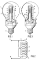
- Fig. 1 shows partly in an elevational view and partly in a cross-section a first embodiment of an electrodeless low-pressure mercury vapour discharge lamp according to the invention;
- Fig. 2 shows diagrammatically the position of the antennas and the windings in the lamp of Fig. 1; and
- Fig. 3 shows also partly in an elevational view and partly in a cross-section a second embodiment of an electrodeless low-pressure mercury vapour discharge lamp according to the invention.
- The lamp of Fig. 1 has a glass bulb-
shaped lamp vessel 1 which is sealed in a gas-tight manner by means of aglass sealing member 2. This seal is realized by means of a sealed connection between theconical wall portion 22 ofmember 2 and thelamp vessel 1. The lamp vessel is filled with mercury and a rare gas such as argon. Aluminescent layer 3 is present on the inner wall of the lamp vessel. The sealingmember 2 has a tubular indentation 4 accommodating a rod-shaped core 5 of ferrite. A first winding 6 surrounds this core and itsends oscillator power supply 9 shown diagrammatically (as described in said Netherlands Patent Application 8004175 laid open to public inspection) which is present in a thin-walledsynthetic material housing 10 connected at one end to thelamp vessel 1 and at the other end having thelamp cap 11 with which the lamp can be screwed into a holder for incandescent lamps. - During operation of the lamp an electric discharge is generated in the lamp vessel by means of winding 6 and the
power supply 9. At one point the winding 6 is electrically connected to a second winding 12 (shown in a broken line) which has a free end 13 (see also Fig. 2). This second winding 12 has substantially the same number of turns as the first winding 6 and is wound in the same way. The two windings are electrically insulated from each other. The potential gradient between the ends of winding 6 is substantially equal to the potential gradient between the ends of winding 12. - According to the invention a wire-
shaped antenna 14 is secured to thefree end 13 of the second winding 12; this antenna is electrically insulated from the twowindings antenna 15 is secured to the end remote from 13. This antenna is also wire-shaped, stretched and electrically insulated from the two windings. Theantennas rod 5. The length ofantenna 15 corresponds to that ofantenna 14. Theantenna 15 is secured proximate the first turn of winding 6. This position is denoted by 16 in the Figure. The antennas are present in the space betweeen the windings and the wall of the tubular indentation 4. - A potential difference having such a value that the lamp readily ignites and re-ignites is present between the
antennas - Fig. 2 shows diagrammatically the circuit of the two windings with the antennas coupled thereto in the lamp of Fig. 1. The output terminals of the high-frequency power supply oscillator are denoted by 17 and 18. The other reference numerals are the same as those in Fig. 1.
- A high-frequency power supply unit (not further shown) is connected between the
terminals Terminal 17 is continuously at substantially zero potential whilst the high-frequency oscillator voltage is applied toterminal 18. This is a so-called asymmetrical source. If the potential atterminal 18 is positive and is zero atterminal 17, the potential atposition 16 is also positive as well as at theantenna 15. At theposition 19 the potential is the same as at terminal 17 (zero in this example). The potential at thefree end 13 is negative and therefore it is also negative at theantenna 14 which is secured to the free end. The maximum potential difference is then present between the twoantennas lamp vessel 1, which leads to a ready ignition of the lamp. Due to the double windings the interference currents on the power supply mains are reduced to a minimum. Also the potentials of theantennas - In the embodiment of the lamp of Fig. 3 the same components of the lamp have the same reference numerals as those in the lamp of Fig. 1. However, in this embodiment of the lamp according to the invention the antennas are not only located next to the
windings strips wall portion 22 of sealing member 2 (for example by means of cement). The said strips (for example a foil) are located substantially opposite to each other and are connected viawires antennas - Several experiments were carried out with the lamp described with reference to Fig. 1. The
lamp vessel 1 accommodated acylindrical ferrite core 5 having a length of approximately 55 mm,diameter 12 mm, surrounded by a first winding having thirteen turns of copper wire (thickness 0.2 mm). The length of the winding measured along the longitudinal axis was 25 mm. The second winding, which was likewise of copper wire of the same thickness, had thirteen turns (length 28 mm). Theantennas - Many variations within the scope of the claims are possible to those skilled in the art. For example, plate-shaped instead of wire-shaped antennas can be used, which may even be accommodated within the lamp vessel. Moreover, two windings may be used, with the first winding being wound clockwise and the second being wound counterclockwise. One antenna is then secured to the free end of the second winding wound counter-clockwise and the other is secured to the end of the first winding. This end is located proximate to the position where the other antenna is secured. As it were, the two windings are then cross-wound.
Claims (4)
- An electrodeless low-pressure discharge lamp having a glass lamp vessel which is sealed in a gas-tight manner and which is filled with at least a metal vapour and a rare gas, said lamp having a first winding which is connected to a high-frequency electric power supply unit and which generates an electric discharge in the lamp vessel, one of the supply wires of the first winding being electrically connected to a supply wire of a second winding which extends at the area of the first winding and which has a free end, the potential gradient between the ends of the first winding being substantially equal to that of the second winding during operation, characterized in that ignition antennas are secured to the free end of the second winding and to one end of the first winding.
- An electrodeless low-pressure discharge lamp as claimed in Claim 1, having a rod-shaped core of a magnetic material, said core being surrounded by the two windings which are present in a tubular indentation in the wall of the lamp vessel, characterized in that the antennas are also present in the said indentation and extend on either side of the rod-shaped core parallel to the longitudinal axis of said core.
- An electrodeless low-pressure discharge lamp as claimed in Claim 1 or 2 in which the lamp vessel is sealed in a gas-tight manner by means of a glass sealing member provided with a tubular indentation for a rod-shaped core and a conical wall portion, characterized in that the antennas extend at least on the outer wall of the conical wall portion.
- An electrodeless low-pressure discharge lamp as claimed in Claim 3, characterized in that the antennas are in the form of aluminium strips which are adhered to the wall and are located substantially opposite to each other.
Applications Claiming Priority (2)
| Application Number | Priority Date | Filing Date | Title |
|---|---|---|---|
| NL8800584 | 1988-03-09 | ||
| NL8800584A NL8800584A (en) | 1988-03-09 | 1988-03-09 | ELECTRESSLESS LOW PRESSURE DISCHARGE LAMP. |
Publications (2)
| Publication Number | Publication Date |
|---|---|
| EP0332263A1 EP0332263A1 (en) | 1989-09-13 |
| EP0332263B1 true EP0332263B1 (en) | 1993-08-11 |
Family
ID=19851910
Family Applications (1)
| Application Number | Title | Priority Date | Filing Date |
|---|---|---|---|
| EP89200531A Expired - Lifetime EP0332263B1 (en) | 1988-03-09 | 1989-03-03 | Electrodeless low-pressure discharge lamp |
Country Status (6)
| Country | Link |
|---|---|
| US (1) | US4977354A (en) |
| EP (1) | EP0332263B1 (en) |
| JP (1) | JPH01265448A (en) |
| CN (1) | CN1022879C (en) |
| DE (1) | DE68908214T2 (en) |
| NL (1) | NL8800584A (en) |
Cited By (1)
| Publication number | Priority date | Publication date | Assignee | Title |
|---|---|---|---|---|
| CN101692418B (en) * | 2004-04-16 | 2011-10-19 | 奥斯兰姆施尔凡尼亚公司 | Electrodeless fluorescent lamp |
Families Citing this family (48)
| Publication number | Priority date | Publication date | Assignee | Title |
|---|---|---|---|---|
| US5264997A (en) * | 1992-03-04 | 1993-11-23 | Dominion Automotive Industries Corp. | Sealed, inductively powered lamp assembly |
| US5397966A (en) * | 1992-05-20 | 1995-03-14 | Diablo Research Corporation | Radio frequency interference reduction arrangements for electrodeless discharge lamps |
| TW214598B (en) * | 1992-05-20 | 1993-10-11 | Diablo Res Corp | Impedance matching and filter network for use with electrodeless discharge lamp |
| US5581157A (en) * | 1992-05-20 | 1996-12-03 | Diablo Research Corporation | Discharge lamps and methods for making discharge lamps |
| US5306986A (en) * | 1992-05-20 | 1994-04-26 | Diablo Research Corporation | Zero-voltage complementary switching high efficiency class D amplifier |
| WO1993026140A1 (en) * | 1992-06-05 | 1993-12-23 | Diablo Research Corporation | Electrodeless discharge lamp containing push-pull class e amplifier and bifilar coil |
| TW210397B (en) * | 1992-06-05 | 1993-08-01 | Diablo Res Corp | Base mechanism to attach an electrodeless discharge light bulb to a socket in a standard lamp harp structure |
| US5572083A (en) * | 1992-07-03 | 1996-11-05 | U.S. Philips Corporation | Electroless low-pressure discharge lamp |
| EP0594245B1 (en) * | 1992-10-21 | 1997-09-17 | Koninklijke Philips Electronics N.V. | Illumination unit and electrodeless low-pressure discharge lamp suitable for use therein |
| EP0594247B1 (en) * | 1992-10-21 | 1997-09-24 | Koninklijke Philips Electronics N.V. | Illumination unit and electrodeless low-pressure discharge lamp suitable for use therein |
| US5619103A (en) * | 1993-11-02 | 1997-04-08 | Wisconsin Alumni Research Foundation | Inductively coupled plasma generating devices |
| BE1007878A3 (en) * | 1993-12-17 | 1995-11-07 | Philips Electronics Nv | LIGHTING UNIT, AND electrodeless low-pressure discharge lamp HOLDER AND POWER DEVICE DESIGNED FOR USE IN LIGHTING UNIT. |
| GB9405371D0 (en) * | 1994-03-18 | 1994-05-04 | Ge Lighting Ltd | Electrodeless fluorescent lamp |
| EP0753203B1 (en) * | 1994-12-23 | 1998-11-18 | Koninklijke Philips Electronics N.V. | Electrodeless low-pressure discharge lamp, and lighting unit provided with such a lamp |
| WO1997040518A1 (en) * | 1996-04-19 | 1997-10-30 | Philips Electronics N.V. | Electrodeless low-pressure discharge lamp |
| US5726523A (en) * | 1996-05-06 | 1998-03-10 | Matsushita Electric Works Research & Development Labratory | Electrodeless fluorescent lamp with bifilar coil and faraday shield |
| CN1055349C (en) * | 1996-05-08 | 2000-08-09 | 李建平 | Non-filament closed ring type gas discharge lamp |
| US5866991A (en) * | 1996-07-17 | 1999-02-02 | General Electric Company | Induction lamp with oppositely oriented coil winding layers |
| US7385357B2 (en) | 1999-06-21 | 2008-06-10 | Access Business Group International Llc | Inductively coupled ballast circuit |
| US7126450B2 (en) | 1999-06-21 | 2006-10-24 | Access Business Group International Llc | Inductively powered apparatus |
| US6825620B2 (en) | 1999-06-21 | 2004-11-30 | Access Business Group International Llc | Inductively coupled ballast circuit |
| US7612528B2 (en) | 1999-06-21 | 2009-11-03 | Access Business Group International Llc | Vehicle interface |
| US6731071B2 (en) * | 1999-06-21 | 2004-05-04 | Access Business Group International Llc | Inductively powered lamp assembly |
| US7462951B1 (en) | 2004-08-11 | 2008-12-09 | Access Business Group International Llc | Portable inductive power station |
| US7408324B2 (en) | 2004-10-27 | 2008-08-05 | Access Business Group International Llc | Implement rack and system for energizing implements |
| US20140375203A1 (en) | 2012-11-26 | 2014-12-25 | Lucidity Lights, Inc. | Induction rf fluorescent lamp with helix mount |
| US9161422B2 (en) | 2012-11-26 | 2015-10-13 | Lucidity Lights, Inc. | Electronic ballast having improved power factor and total harmonic distortion |
| US9209008B2 (en) | 2012-11-26 | 2015-12-08 | Lucidity Lights, Inc. | Fast start induction RF fluorescent light bulb |
| US10128101B2 (en) | 2012-11-26 | 2018-11-13 | Lucidity Lights, Inc. | Dimmable induction RF fluorescent lamp with reduced electromagnetic interference |
| US10141179B2 (en) | 2012-11-26 | 2018-11-27 | Lucidity Lights, Inc. | Fast start RF induction lamp with metallic structure |
| US8941304B2 (en) | 2012-11-26 | 2015-01-27 | Lucidity Lights, Inc. | Fast start dimmable induction RF fluorescent light bulb |
| US8872426B2 (en) | 2012-11-26 | 2014-10-28 | Lucidity Lights, Inc. | Arrangements and methods for triac dimming of gas discharge lamps powered by electronic ballasts |
| US9460907B2 (en) | 2012-11-26 | 2016-10-04 | Lucidity Lights, Inc. | Induction RF fluorescent lamp with load control for external dimming device |
| US9129792B2 (en) | 2012-11-26 | 2015-09-08 | Lucidity Lights, Inc. | Fast start induction RF fluorescent lamp with reduced electromagnetic interference |
| US9129791B2 (en) | 2012-11-26 | 2015-09-08 | Lucidity Lights, Inc. | RF coupler stabilization in an induction RF fluorescent light bulb |
| US20140145609A1 (en) * | 2012-11-26 | 2014-05-29 | Lucidity Lights, Inc. | Rf induction lamp with reduced electromagnetic interference |
| US9305765B2 (en) | 2012-11-26 | 2016-04-05 | Lucidity Lights, Inc. | High frequency induction lighting |
| US8698413B1 (en) | 2012-11-26 | 2014-04-15 | Lucidity Lights, Inc. | RF induction lamp with reduced electromagnetic interference |
| US9524861B2 (en) | 2012-11-26 | 2016-12-20 | Lucidity Lights, Inc. | Fast start RF induction lamp |
| US9245734B2 (en) | 2012-11-26 | 2016-01-26 | Lucidity Lights, Inc. | Fast start induction RF fluorescent lamp with burst-mode dimming |
| US10529551B2 (en) | 2012-11-26 | 2020-01-07 | Lucidity Lights, Inc. | Fast start fluorescent light bulb |
| USD745981S1 (en) | 2013-07-19 | 2015-12-22 | Lucidity Lights, Inc. | Inductive lamp |
| USD745982S1 (en) | 2013-07-19 | 2015-12-22 | Lucidity Lights, Inc. | Inductive lamp |
| USD746490S1 (en) | 2013-07-19 | 2015-12-29 | Lucidity Lights, Inc. | Inductive lamp |
| USD747009S1 (en) | 2013-08-02 | 2016-01-05 | Lucidity Lights, Inc. | Inductive lamp |
| USD747507S1 (en) | 2013-08-02 | 2016-01-12 | Lucidity Lights, Inc. | Inductive lamp |
| USD854198S1 (en) | 2017-12-28 | 2019-07-16 | Lucidity Lights, Inc. | Inductive lamp |
| US10236174B1 (en) | 2017-12-28 | 2019-03-19 | Lucidity Lights, Inc. | Lumen maintenance in fluorescent lamps |
Family Cites Families (3)
| Publication number | Priority date | Publication date | Assignee | Title |
|---|---|---|---|---|
| US4048541A (en) * | 1976-06-14 | 1977-09-13 | Solitron Devices, Inc. | Crystal controlled oscillator circuit for illuminating electrodeless fluorescent lamp |
| US4253047A (en) * | 1977-05-23 | 1981-02-24 | General Electric Company | Starting electrodes for solenoidal electric field discharge lamps |
| NL8401307A (en) * | 1984-04-24 | 1985-11-18 | Philips Nv | ELECTRESSLESS LOW PRESSURE DISCHARGE LAMP. |
-
1988
- 1988-03-09 NL NL8800584A patent/NL8800584A/en not_active Application Discontinuation
-
1989
- 1989-03-01 US US07/317,374 patent/US4977354A/en not_active Expired - Fee Related
- 1989-03-03 DE DE89200531T patent/DE68908214T2/en not_active Expired - Fee Related
- 1989-03-03 EP EP89200531A patent/EP0332263B1/en not_active Expired - Lifetime
- 1989-03-06 CN CN89101293.1A patent/CN1022879C/en not_active Expired - Fee Related
- 1989-03-06 JP JP1052162A patent/JPH01265448A/en active Pending
Cited By (1)
| Publication number | Priority date | Publication date | Assignee | Title |
|---|---|---|---|---|
| CN101692418B (en) * | 2004-04-16 | 2011-10-19 | 奥斯兰姆施尔凡尼亚公司 | Electrodeless fluorescent lamp |
Also Published As
| Publication number | Publication date |
|---|---|
| NL8800584A (en) | 1989-10-02 |
| DE68908214D1 (en) | 1993-09-16 |
| EP0332263A1 (en) | 1989-09-13 |
| JPH01265448A (en) | 1989-10-23 |
| CN1022879C (en) | 1993-11-24 |
| US4977354A (en) | 1990-12-11 |
| CN1035915A (en) | 1989-09-27 |
| DE68908214T2 (en) | 1994-03-03 |
Similar Documents
| Publication | Publication Date | Title |
|---|---|---|
| EP0332263B1 (en) | Electrodeless low-pressure discharge lamp | |
| EP0162504B1 (en) | Electrodeless low-pressure discharge lamp | |
| EP0294004B1 (en) | Electrodeless low pressure discharge lamp | |
| US5325024A (en) | Light source including parallel driven low pressure RF fluorescent lamps | |
| EP0313027B1 (en) | Arc discharge lamp with ultraviolet radiation starting source | |
| EP0967631B1 (en) | Capacitive glow starting of ceramic high intensity discharge devices | |
| US5239238A (en) | Electrodeless low-pressure mercury vapour discharge lamp | |
| EP0198523B1 (en) | Electrodeless low-pressure discharge lamp | |
| GB2174238A (en) | Electrodeless low-pressure discharge lamp | |
| US4959584A (en) | Luminaire for an electrodeless high intensity discharge lamp | |
| US20030006705A1 (en) | Coil antenna/protection for ceramic metal halide lamps | |
| EP0198524A1 (en) | Electrodeless low-pressure discharge lamp | |
| US4661746A (en) | Electrodeless low-pressure discharge lamp | |
| US5838104A (en) | Shield for high pressure discharge lamps | |
| EP0089582A2 (en) | Intimate contact starting aid for arc lamps | |
| US6924599B2 (en) | Dielectric barrier discharge lamp with starting aid | |
| US2682008A (en) | Seal stem for electric discharge devices | |
| EP0184217A2 (en) | Low pressure arc discharge tube having increased voltage | |
| EP1001451B1 (en) | Arc discharge lamp containing barium and having an arc tube of yttrium, gadolinium or terbium oxide | |
| JPH11288697A (en) | Fluorescent lamp | |
| JPH10233192A (en) | Flat fluorescent lamp device | |
| JP2004207220A (en) | High pressure discharge lamp, lamp socket, and lighting system | |
| CA2458891A1 (en) | Low-pressure discharge lamp | |
| JPH05182640A (en) | Solenoid magnetic field type discharge lamp |
Legal Events
| Date | Code | Title | Description |
|---|---|---|---|
| PUAI | Public reference made under article 153(3) epc to a published international application that has entered the european phase |
Free format text: ORIGINAL CODE: 0009012 |
|
| AK | Designated contracting states |
Kind code of ref document: A1 Designated state(s): BE DE FR GB NL |
|
| 17P | Request for examination filed |
Effective date: 19900309 |
|
| 17Q | First examination report despatched |
Effective date: 19920921 |
|
| GRAA | (expected) grant |
Free format text: ORIGINAL CODE: 0009210 |
|
| AK | Designated contracting states |
Kind code of ref document: B1 Designated state(s): BE DE FR GB NL |
|
| REF | Corresponds to: |
Ref document number: 68908214 Country of ref document: DE Date of ref document: 19930916 |
|
| ET | Fr: translation filed | ||
| PLBE | No opposition filed within time limit |
Free format text: ORIGINAL CODE: 0009261 |
|
| STAA | Information on the status of an ep patent application or granted ep patent |
Free format text: STATUS: NO OPPOSITION FILED WITHIN TIME LIMIT |
|
| 26N | No opposition filed | ||
| PGFP | Annual fee paid to national office [announced via postgrant information from national office to epo] |
Ref country code: BE Payment date: 19950307 Year of fee payment: 7 |
|
| PGFP | Annual fee paid to national office [announced via postgrant information from national office to epo] |
Ref country code: NL Payment date: 19950331 Year of fee payment: 7 |
|
| REG | Reference to a national code |
Ref country code: FR Ref legal event code: CD |
|
| NLT1 | Nl: modifications of names registered in virtue of documents presented to the patent office pursuant to art. 16 a, paragraph 1 |
Owner name: PHILIPS ELECTRONICS N.V. |
|
| PG25 | Lapsed in a contracting state [announced via postgrant information from national office to epo] |
Ref country code: BE Effective date: 19960331 |
|
| BERE | Be: lapsed |
Owner name: PHILIPS ELECTRONICS N.V. Effective date: 19960331 |
|
| PG25 | Lapsed in a contracting state [announced via postgrant information from national office to epo] |
Ref country code: NL Effective date: 19961001 |
|
| NLV4 | Nl: lapsed or anulled due to non-payment of the annual fee |
Effective date: 19961001 |
|
| PGFP | Annual fee paid to national office [announced via postgrant information from national office to epo] |
Ref country code: GB Payment date: 19980302 Year of fee payment: 10 |
|
| PGFP | Annual fee paid to national office [announced via postgrant information from national office to epo] |
Ref country code: FR Payment date: 19980324 Year of fee payment: 10 |
|
| PGFP | Annual fee paid to national office [announced via postgrant information from national office to epo] |
Ref country code: DE Payment date: 19980526 Year of fee payment: 10 |
|
| REG | Reference to a national code |
Ref country code: FR Ref legal event code: CD |
|
| PG25 | Lapsed in a contracting state [announced via postgrant information from national office to epo] |
Ref country code: GB Free format text: LAPSE BECAUSE OF NON-PAYMENT OF DUE FEES Effective date: 19990303 |
|
| GBPC | Gb: european patent ceased through non-payment of renewal fee |
Effective date: 19990303 |
|
| PG25 | Lapsed in a contracting state [announced via postgrant information from national office to epo] |
Ref country code: FR Free format text: LAPSE BECAUSE OF NON-PAYMENT OF DUE FEES Effective date: 19991130 |
|
| REG | Reference to a national code |
Ref country code: FR Ref legal event code: ST |
|
| PG25 | Lapsed in a contracting state [announced via postgrant information from national office to epo] |
Ref country code: DE Free format text: LAPSE BECAUSE OF NON-PAYMENT OF DUE FEES Effective date: 20000101 |