EP0183500A2 - Apparatus for cleaning pipes - Google Patents
Apparatus for cleaning pipes Download PDFInfo
- Publication number
- EP0183500A2 EP0183500A2 EP85308528A EP85308528A EP0183500A2 EP 0183500 A2 EP0183500 A2 EP 0183500A2 EP 85308528 A EP85308528 A EP 85308528A EP 85308528 A EP85308528 A EP 85308528A EP 0183500 A2 EP0183500 A2 EP 0183500A2
- Authority
- EP
- European Patent Office
- Prior art keywords
- collar
- scraper
- riser
- spaced
- scraper member
- Prior art date
- Legal status (The legal status is an assumption and is not a legal conclusion. Google has not performed a legal analysis and makes no representation as to the accuracy of the status listed.)
- Withdrawn
Links
- 238000004140 cleaning Methods 0.000 title claims abstract description 7
- 239000000463 material Substances 0.000 description 4
- 229910001369 Brass Inorganic materials 0.000 description 3
- 239000010951 brass Substances 0.000 description 3
- 239000000969 carrier Substances 0.000 description 3
- 239000004033 plastic Substances 0.000 description 3
- 229920003023 plastic Polymers 0.000 description 3
- 229920002302 Nylon 6,6 Polymers 0.000 description 2
- 239000002184 metal Substances 0.000 description 2
- 238000007790 scraping Methods 0.000 description 2
- 229910000760 Hardened steel Inorganic materials 0.000 description 1
- 229910000831 Steel Inorganic materials 0.000 description 1
- 238000011109 contamination Methods 0.000 description 1
- 238000005260 corrosion Methods 0.000 description 1
- 230000007797 corrosion Effects 0.000 description 1
- 230000000694 effects Effects 0.000 description 1
- 238000000034 method Methods 0.000 description 1
- 238000012986 modification Methods 0.000 description 1
- 230000004048 modification Effects 0.000 description 1
- 239000010959 steel Substances 0.000 description 1
- XLYOFNOQVPJJNP-UHFFFAOYSA-N water Substances O XLYOFNOQVPJJNP-UHFFFAOYSA-N 0.000 description 1
Images


Classifications
-
- B—PERFORMING OPERATIONS; TRANSPORTING
- B08—CLEANING
- B08B—CLEANING IN GENERAL; PREVENTION OF FOULING IN GENERAL
- B08B9/00—Cleaning hollow articles by methods or apparatus specially adapted thereto
- B08B9/02—Cleaning pipes or tubes or systems of pipes or tubes
- B08B9/023—Cleaning the external surface
-
- E—FIXED CONSTRUCTIONS
- E21—EARTH DRILLING; MINING
- E21B—EARTH DRILLING, e.g. DEEP DRILLING; OBTAINING OIL, GAS, WATER, SOLUBLE OR MELTABLE MATERIALS OR A SLURRY OF MINERALS FROM WELLS
- E21B41/00—Equipment or details not covered by groups E21B15/00 - E21B40/00
- E21B41/04—Manipulators for underwater operations, e.g. temporarily connected to well heads
Definitions
- This invention relates to apparatus for cleaning underwater structures, for example pipes and the like.
- pipelines and other tubular structures can become contaminated on their outer surfaces with marine growth. Such contamination increases the weight and drag of the members and can allow corrosion damage of the structures.
- apparatus for cleaning an underwater structure comprising a collar for fitment around a structure to be cleaned, a scraper member extending inwardly of the collar so as to engage the structure in use, resilient bias means for urging the scraper inwardly of the collar, and means for use in moving the scraper member along the structure.
- scraper member Preferably more than one scraper member is provided; a series of such members may be spaced around an inner face of the apparatus.
- a further series of scraper members may be provided in similar fashion, the members in the further series being spaced longitudinally and offset laterally from the scraper members of the first series.
- the scraper members may be generally wedge-shaped with the leading edge forming a cutter for engaging a pipe at a suitable angle to remove marine growth as it travels along the underwater structure.
- the material of the scraper members may be selected according to the nature of the marine growth to be removed and the material of the structure, and may range from plastics material such as Nylon 66 to metal such as hardened steel.
- the resilient bias means is preferably a spring, for example a leaf spring secured at one end to the collar and at its other end to the scraper member.
- the connection to the scraper member may be shearable so that if the member engages in use with a fixed projection on the structure being cleaned it shears off instead of damaging the structure.
- the collar is preferably split longitudinally for fitment around a structure, the portions being hinged together for easy fixing.
- the means for use in moving the scraper member along the structure may be for example one or more pulleys around which passes a cable or other flexible connector.
- the cable may be connected to a winch at the top of the structure, actuation of the winch drawing in the cable and pulling the apparatus upwardly along the structure.
- means are provided for centring the collar around the structure; this may be in the form of wheels or rollers mounted on and disposed around the collar and extending inwardly of it so as to run on the surface of the structure.
- FIG. 1 the apparatus of the embodiment of the invention shown in Figs. 1, 2 and has a cylindrical collar 1 which is split into two semi-cylindrical portions 2 interconnected by hinges 3.
- the collar 1 is of sufficient internal diameter to envelope a marine riser 4 to be cleaned, with a clearance between them, and consists of outer connecting bars 1A with annular carriers 1B, 1C secured to their inner face.
- the carrier 1B has bolted to it at 5 six leaf springs 6 equispaced around it, and the free end of each leaf spring 6 has bolted to it by brass bolts a scraper block 7.
- the scraper blocks 7 in this embodiment are of Nylon 66 aid are arranged in two annular rows 7A and 7B.
- the blocks 7B are spaced axially of the collar 1 from the blocks 7A, and are offset circumferentially of the blocks 7A so that, as can be seen from Fig. 2, the blocks 7A and 7B together provide effective scraping faces around the entire pipe circumference.
- the blocks 7A and 7B indeed, overlap when in use on the riser 4 in this example.
- Each scraper block 7 is generally wedge-shaped and presents a cutting edge 8 at a shallow angle to the surface of the riser 4.
- the leaf springs 6 bias the scraper blocks 7 towards the riser 4, and adjustment screws 9 through the outer shell 1A abut against the springs 6 to increase or decrease the biassing force exerted on the scraper blocks 7.
- a limit ring 10 is suspended on support posts 11 extending inwardly from the shell 1A between the leaf springs 6 in order to limit the extent of inward movement of the springs 6 in the event of one or more of the scraper blocks 7 gouging into the wall of the riser 4.
- Limit rollers 12 are provided on the carriers 1C at each end of the collar 1. These rollers 12 are of plastics material and are arranged to engage the riser 4 in preference to the steel carriers 1B, 1C so as to prevent metal-to-metal contact which could damage the riser 4.
- guide rollers 13 are provided at an end portion of the collar 1.
- the collar 1 In use, where the riser 4 extends downwardly from an oil platform 17, the collar 1 is opened about its hinges 3 and around the riser 4 at deck level. The collar portions 2 are then secured together by bolts or over-centre clamps (not shown) so that it envelopes the riser 4.
- a wire 14 is fed around the guide rollers 13 from a winch 15 and secured to fixture 16 on the platform 17. The winch 15 is actuated to feed out the wire 14, allowing the apparatus to move downwardly on the riser 4, the only contact with the riser wall being through the scraper blocks 7 which centre the collar 1 around the riser 4 by virtue of the leaf springs 6. As the apparatus moves down the riser 4 the scraper blocks 7 ride over marine growth easily due to their chamfered faces 16.
- the winch 15 When the apparatus is below the area of the riser to be cleaned, the winch 15 is reversed to retract the wire 14 and pull the apparatus upwardly.
- the leaf springs 6 urge the cutting edges 8 of the scraper blocks 7 against the riser 4, cutting through and removing marine growth.
- the apparatus is returned to the platform deck where it is removed from the riser 4 by unclamping the collar portions 2.
- the segmental arrangement of the scraper blocks 7 and the adjustable leaf springs 6 allows the apparatus to be used on risers, pipes and tubulars of different diameters.
- the apparatus of this embodiment is generally similar to that of Figs. 1, 2 and 3, and equivalent parts will be identified by the same reference numerals.
- the collar 1 is made up of axially-spaced rings 1C, 1D which are interconnected by circumferentially-spaced connecting bars lA.
- the bars lA and rings 1C, 1D are bolted together so as to be demountable.
- the rings 1C, 1D are hinged at 3 to form semi-cylindrical portions and lockable by a toggle bolt 13 on one portion which engages with and is tightened against bracket 14 on the other portion.
- a securing pin 15 is also inserted through correspondingly-apertured brackets 16 on the two portions as additional fixing.
- Anti-scuff buttons 17 protrude inwardly of the collar 1 to reduce frictional damage between the pipe to be cleaned and the collar 1.
- limit rollers 12 are provided only on the ring 1C and are inwardly-directed as shown in Fig. 4, and the plastics scraper blocks 7 are secured to their leaf springs 6 by shearable brass bolts 18.
- three pulleys 13A, 13B and 13C are mounted on the ring 1D around its periphery, and the wire 14 passes around them between the winch 15 and fixed point 16 as shown in Fig. 3.
- the pulleys 13A, 13B and 13C are rotatable on bolted axles 20 which are held on brackets 19.
- the brackets 19A for the pulleys 13A and 13C are pivotally mounted on the ring 1D so as to pivot freely in bearings about the axis of the wire 14 where it extends between the pulleys 13A and 13B, and 13B and 13C respectively.
- the limit ring 10 can be dispensed with and replaced by projecting buttons secured on the inwardly-directed face of the leaf springs 6, the buttons engaging the riser's outer face if the springs 6 deflect towards the riser beyond a predetermined desired extent.
- the wedge shape of the block 7 causes it to rotate about the obstruction and bend the leaf spring 6 towards the riser along its length.
- ring 1D of Fig. 4 may be replaced by a pair of axially-spaced rings which are interconnected by extensions to the bars lA.
- Each ring has its inwardly-directed face inclined inwardly towards the ring 1C, and the leaf springs 6 are secured to these inclined faces. The inclination directs the springs 6 towards the riser in use and can obviate the need for the adjustment screws 9 in the illustrated embodiments.
- the ring which is furthest from the winch may be grooved to allow free passage of the leaf springs secured to the other ring.
- a camera array may be provided on the apparatus to observe the cleaning effect, and spring-loaded rollers may be provided to engage the riser surface and centre the apparatus.
Abstract
Description
- This invention relates to apparatus for cleaning underwater structures, for example pipes and the like.
- In the offshore oil industry marine risers, pipelines and other tubular structures can become contaminated on their outer surfaces with marine growth. Such contamination increases the weight and drag of the members and can allow corrosion damage of the structures.
- Previously-proposed methods of cleaning such members have involved divers working underwater to remove the growth using hand-held scraping and chipping tools, or directing high-pressure water jets against the member's surface.
- According to the present invention there is provided apparatus for cleaning an underwater structure comprising a collar for fitment around a structure to be cleaned, a scraper member extending inwardly of the collar so as to engage the structure in use, resilient bias means for urging the scraper inwardly of the collar, and means for use in moving the scraper member along the structure.
- Preferably more than one scraper member is provided; a series of such members may be spaced around an inner face of the apparatus. A further series of scraper members may be provided in similar fashion, the members in the further series being spaced longitudinally and offset laterally from the scraper members of the first series.
- The scraper members may be generally wedge-shaped with the leading edge forming a cutter for engaging a pipe at a suitable angle to remove marine growth as it travels along the underwater structure. The material of the scraper members may be selected according to the nature of the marine growth to be removed and the material of the structure, and may range from plastics material such as Nylon 66 to metal such as hardened steel.
- The resilient bias means is preferably a spring, for example a leaf spring secured at one end to the collar and at its other end to the scraper member. The connection to the scraper member may be shearable so that if the member engages in use with a fixed projection on the structure being cleaned it shears off instead of damaging the structure.
- The collar is preferably split longitudinally for fitment around a structure, the portions being hinged together for easy fixing.
- The means for use in moving the scraper member along the structure may be for example one or more pulleys around which passes a cable or other flexible connector. The cable may be connected to a winch at the top of the structure, actuation of the winch drawing in the cable and pulling the apparatus upwardly along the structure.
- Preferably means are provided for centring the collar around the structure; this may be in the form of wheels or rollers mounted on and disposed around the collar and extending inwardly of it so as to run on the surface of the structure.
- Embodiments of this invention will now be described by way of example with reference to the accompanying drawings in which:
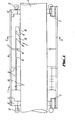
- Fig. 1 is a side part-sectional view of apparatus of this invention in use;
- Fig. 2 is an end sectional view on X-X of Fig. 1 with the springs and collar omitted;
- Fig. 3 is a schematic side view showing the apparatus of Fig. 1 in use;
- Fig. 4 is a side part-sectional view of an alternative form of the apparatus of this invention; and
- Fig. 5 is an end view of the apparatus of Fig. with the scrapers removed.
- Referring now to the drawings, the apparatus of the embodiment of the invention shown in Figs. 1, 2 and has a
cylindrical collar 1 which is split into two semi-cylindrical portions 2 interconnected byhinges 3. Thecollar 1 is of sufficient internal diameter to envelope amarine riser 4 to be cleaned, with a clearance between them, and consists of outer connecting bars 1A with annular carriers 1B, 1C secured to their inner face. - The carrier 1B has bolted to it at 5 six
leaf springs 6 equispaced around it, and the free end of eachleaf spring 6 has bolted to it by brass bolts ascraper block 7. Thescraper blocks 7 in this embodiment are of Nylon 66 aid are arranged in twoannular rows blocks 7B are spaced axially of thecollar 1 from theblocks 7A, and are offset circumferentially of theblocks 7A so that, as can be seen from Fig. 2, theblocks blocks riser 4 in this example. - Each
scraper block 7 is generally wedge-shaped and presents a cutting edge 8 at a shallow angle to the surface of theriser 4. - The
leaf springs 6 bias the scraper blocks 7 towards theriser 4, and adjustment screws 9 through the outer shell 1A abut against thesprings 6 to increase or decrease the biassing force exerted on thescraper blocks 7. - A
limit ring 10 is suspended on support posts 11 extending inwardly from the shell 1A between theleaf springs 6 in order to limit the extent of inward movement of thesprings 6 in the event of one or more of thescraper blocks 7 gouging into the wall of theriser 4. -
Limit rollers 12 are provided on the carriers 1C at each end of thecollar 1. Theserollers 12 are of plastics material and are arranged to engage theriser 4 in preference to the steel carriers 1B, 1C so as to prevent metal-to-metal contact which could damage theriser 4. - As shown in Fig. 3, guide rollers 13 (not shown in Figs. 1 and 2) are provided at an end portion of the
collar 1. - In use, where the
riser 4 extends downwardly from an oil platform 17, thecollar 1 is opened about itshinges 3 and around theriser 4 at deck level. The collar portions 2 are then secured together by bolts or over-centre clamps (not shown) so that it envelopes theriser 4. Awire 14 is fed around theguide rollers 13 from awinch 15 and secured tofixture 16 on the platform 17. Thewinch 15 is actuated to feed out thewire 14, allowing the apparatus to move downwardly on theriser 4, the only contact with the riser wall being through thescraper blocks 7 which centre thecollar 1 around theriser 4 by virtue of theleaf springs 6. As the apparatus moves down theriser 4 the scraper blocks 7 ride over marine growth easily due to theirchamfered faces 16. - When the apparatus is below the area of the riser to be cleaned, the
winch 15 is reversed to retract thewire 14 and pull the apparatus upwardly. Theleaf springs 6 urge the cutting edges 8 of the scraper blocks 7 against theriser 4, cutting through and removing marine growth. - On finishing, the apparatus is returned to the platform deck where it is removed from the
riser 4 by unclamping the collar portions 2. - The segmental arrangement of the scraper blocks 7 and the
adjustable leaf springs 6 allows the apparatus to be used on risers, pipes and tubulars of different diameters. - Referring now to Figs. 4 and 5, the apparatus of this embodiment is generally similar to that of Figs. 1, 2 and 3, and equivalent parts will be identified by the same reference numerals. In Fig. 4 and 5 the
collar 1 is made up of axially-spaced rings 1C, 1D which are interconnected by circumferentially-spaced connecting bars lA. The bars lA and rings 1C, 1D are bolted together so as to be demountable. The rings 1C, 1D are hinged at 3 to form semi-cylindrical portions and lockable by atoggle bolt 13 on one portion which engages with and is tightened againstbracket 14 on the other portion. A securingpin 15 is also inserted through correspondingly-aperturedbrackets 16 on the two portions as additional fixing. Anti-scuff buttons 17 protrude inwardly of thecollar 1 to reduce frictional damage between the pipe to be cleaned and thecollar 1. - In this case the
limit rollers 12 are provided only on the ring 1C and are inwardly-directed as shown in Fig. 4, and theplastics scraper blocks 7 are secured to theirleaf springs 6 byshearable brass bolts 18. - At the end of the apparatus which is closest to the winch in use, three
pulleys wire 14 passes around them between thewinch 15 and fixedpoint 16 as shown in Fig. 3. Thepulleys bolted axles 20 which are held onbrackets 19. Thebrackets 19A for thepulleys wire 14 where it extends between thepulleys wire 14; this is especially useful when the apparatus is near the top of its travel, and thewire 14 forms a very large angle between the sections leaving thepulley 13A and thepulley 13C. - In use, the apparatus of Figs. 4 and 5 operates in the same manner as that of Figs. 1, 2 and 3.
- Various modifications can be made to the apparatus of these embodiments. For example the
limit ring 10 can be dispensed with and replaced by projecting buttons secured on the inwardly-directed face of theleaf springs 6, the buttons engaging the riser's outer face if thesprings 6 deflect towards the riser beyond a predetermined desired extent. In the event of ascraper block 7 engaging an immovable obstruction on a riser, the wedge shape of theblock 7 causes it to rotate about the obstruction and bend theleaf spring 6 towards the riser along its length. When the button engages the riser, further rotation is prevented and the scraper block will either ride over the obstruction or shear itsbrass retaining bolts 18; the apparatus then is free to continue. - Further, the ring 1D of Fig. 4 may be replaced by a pair of axially-spaced rings which are interconnected by extensions to the bars lA. Each ring has its inwardly-directed face inclined inwardly towards the ring 1C, and the
leaf springs 6 are secured to these inclined faces. The inclination directs thesprings 6 towards the riser in use and can obviate the need for the adjustment screws 9 in the illustrated embodiments. The ring which is furthest from the winch may be grooved to allow free passage of the leaf springs secured to the other ring. - A camera array may be provided on the apparatus to observe the cleaning effect, and spring-loaded rollers may be provided to engage the riser surface and centre the apparatus.
Claims (10)
Applications Claiming Priority (2)
| Application Number | Priority Date | Filing Date | Title |
|---|---|---|---|
| GB848429892A GB8429892D0 (en) | 1984-11-27 | 1984-11-27 | Cleaning pipes |
| GB8429892 | 1984-11-27 |
Publications (2)
| Publication Number | Publication Date |
|---|---|
| EP0183500A2 true EP0183500A2 (en) | 1986-06-04 |
| EP0183500A3 EP0183500A3 (en) | 1987-12-02 |
Family
ID=10570316
Family Applications (1)
| Application Number | Title | Priority Date | Filing Date |
|---|---|---|---|
| EP85308528A Withdrawn EP0183500A3 (en) | 1984-11-27 | 1985-11-25 | Apparatus for cleaning pipes |
Country Status (5)
| Country | Link |
|---|---|
| US (1) | US4688290A (en) |
| EP (1) | EP0183500A3 (en) |
| AU (1) | AU5043585A (en) |
| GB (1) | GB8429892D0 (en) |
| NO (1) | NO854722L (en) |
Cited By (2)
| Publication number | Priority date | Publication date | Assignee | Title |
|---|---|---|---|---|
| WO1988008808A1 (en) * | 1987-05-15 | 1988-11-17 | Iev International Pty. Limited | Apparatus for the combatting of marine growth on offshore structures |
| WO2009105898A1 (en) * | 2008-02-28 | 2009-09-03 | Welaptega Marine Limited | Tubular measurement system |
Families Citing this family (24)
| Publication number | Priority date | Publication date | Assignee | Title |
|---|---|---|---|---|
| ITRN990037A1 (en) * | 1999-12-23 | 2001-06-23 | Lisciani Trafilerie Srl R | DEVICE FOR MECHANICAL CLEANING OF VERGELLA FOR PROFILED METAL WIRES |
| US20040221929A1 (en) * | 2003-05-09 | 2004-11-11 | Hebda John J. | Processing of titanium-aluminum-vanadium alloys and products made thereby |
| FR2859932B1 (en) * | 2003-09-19 | 2006-12-01 | Bmts Sa | MACHINE TO ROTATE PILES |
| US7837812B2 (en) * | 2004-05-21 | 2010-11-23 | Ati Properties, Inc. | Metastable beta-titanium alloys and methods of processing the same by direct aging |
| US8337750B2 (en) | 2005-09-13 | 2012-12-25 | Ati Properties, Inc. | Titanium alloys including increased oxygen content and exhibiting improved mechanical properties |
| US7611592B2 (en) | 2006-02-23 | 2009-11-03 | Ati Properties, Inc. | Methods of beta processing titanium alloys |
| US7765632B2 (en) * | 2006-06-05 | 2010-08-03 | Oceaneering International, Inc. | Subsea conduit cleaning tool |
| US8007595B2 (en) * | 2008-02-28 | 2011-08-30 | Welaptega Marine Limited | Method for in-situ cleaning and inspecting of a tubular |
| US20120006554A1 (en) * | 2009-02-26 | 2012-01-12 | Donald Wayne Allen | Methods and devices of cleaning subsea structures |
| US10053758B2 (en) * | 2010-01-22 | 2018-08-21 | Ati Properties Llc | Production of high strength titanium |
| US9255316B2 (en) | 2010-07-19 | 2016-02-09 | Ati Properties, Inc. | Processing of α+β titanium alloys |
| US8499605B2 (en) | 2010-07-28 | 2013-08-06 | Ati Properties, Inc. | Hot stretch straightening of high strength α/β processed titanium |
| US8613818B2 (en) | 2010-09-15 | 2013-12-24 | Ati Properties, Inc. | Processing routes for titanium and titanium alloys |
| US9206497B2 (en) | 2010-09-15 | 2015-12-08 | Ati Properties, Inc. | Methods for processing titanium alloys |
| US10513755B2 (en) | 2010-09-23 | 2019-12-24 | Ati Properties Llc | High strength alpha/beta titanium alloy fasteners and fastener stock |
| US8652400B2 (en) | 2011-06-01 | 2014-02-18 | Ati Properties, Inc. | Thermo-mechanical processing of nickel-base alloys |
| US9200490B2 (en) * | 2012-09-28 | 2015-12-01 | Thomas Engineering Solutions & Consulting, Llc | Methods for internal cleaning and inspection of tubulars |
| US9050647B2 (en) | 2013-03-15 | 2015-06-09 | Ati Properties, Inc. | Split-pass open-die forging for hard-to-forge, strain-path sensitive titanium-base and nickel-base alloys |
| US9869003B2 (en) | 2013-02-26 | 2018-01-16 | Ati Properties Llc | Methods for processing alloys |
| US9192981B2 (en) | 2013-03-11 | 2015-11-24 | Ati Properties, Inc. | Thermomechanical processing of high strength non-magnetic corrosion resistant material |
| US9777361B2 (en) | 2013-03-15 | 2017-10-03 | Ati Properties Llc | Thermomechanical processing of alpha-beta titanium alloys |
| US11111552B2 (en) | 2013-11-12 | 2021-09-07 | Ati Properties Llc | Methods for processing metal alloys |
| US10094003B2 (en) | 2015-01-12 | 2018-10-09 | Ati Properties Llc | Titanium alloy |
| US10502252B2 (en) | 2015-11-23 | 2019-12-10 | Ati Properties Llc | Processing of alpha-beta titanium alloys |
Citations (2)
| Publication number | Priority date | Publication date | Assignee | Title |
|---|---|---|---|---|
| US2782436A (en) * | 1955-04-05 | 1957-02-26 | John S Tomer | Pipe cleaner with tandem scraping heads |
| US2813285A (en) * | 1954-03-01 | 1957-11-19 | Aslin James Kenneth | Axial scraping device for pipe cleaning |
-
1984
- 1984-11-27 GB GB848429892A patent/GB8429892D0/en active Pending
-
1985
- 1985-11-25 EP EP85308528A patent/EP0183500A3/en not_active Withdrawn
- 1985-11-26 AU AU50435/85A patent/AU5043585A/en not_active Abandoned
- 1985-11-26 NO NO854722A patent/NO854722L/en unknown
- 1985-12-20 US US06/811,500 patent/US4688290A/en not_active Expired - Fee Related
Patent Citations (2)
| Publication number | Priority date | Publication date | Assignee | Title |
|---|---|---|---|---|
| US2813285A (en) * | 1954-03-01 | 1957-11-19 | Aslin James Kenneth | Axial scraping device for pipe cleaning |
| US2782436A (en) * | 1955-04-05 | 1957-02-26 | John S Tomer | Pipe cleaner with tandem scraping heads |
Cited By (5)
| Publication number | Priority date | Publication date | Assignee | Title |
|---|---|---|---|---|
| WO1988008808A1 (en) * | 1987-05-15 | 1988-11-17 | Iev International Pty. Limited | Apparatus for the combatting of marine growth on offshore structures |
| EP0358682A1 (en) * | 1987-05-15 | 1990-03-21 | Iev Int Pty Ltd | Apparatus for the combatting of marine growth on offshore structures. |
| EP0358682A4 (en) * | 1987-05-15 | 1992-01-08 | Iev Int Pty Ltd | Apparatus for the combatting of marine growth on offshore structures |
| WO2009105898A1 (en) * | 2008-02-28 | 2009-09-03 | Welaptega Marine Limited | Tubular measurement system |
| AU2009219035B2 (en) * | 2008-02-28 | 2012-02-23 | Welaptega Marine Limited | Tubular measurement system |
Also Published As
| Publication number | Publication date |
|---|---|
| EP0183500A3 (en) | 1987-12-02 |
| GB8429892D0 (en) | 1985-01-03 |
| US4688290A (en) | 1987-08-25 |
| NO854722L (en) | 1986-05-28 |
| AU5043585A (en) | 1986-06-05 |
Similar Documents
| Publication | Publication Date | Title |
|---|---|---|
| US4688290A (en) | Apparatus for cleaning pipes | |
| US6264537B1 (en) | Multi-function pipeline weld removal apparatus | |
| US20100226724A1 (en) | Pile cleaner apparatus | |
| AU617320B2 (en) | Apparatus for the combatting of marine growth on offshore structures | |
| EP3469247B1 (en) | Robot for renovating penstocks, provided with an anti-twisting moving system | |
| US5439320A (en) | Pipe splitting and spreading system | |
| US4538316A (en) | Pipe cleaning equipment | |
| AU2012200634B2 (en) | Marine riser tensioner | |
| EP2697481B1 (en) | Method and apparatus for cleaning fluid conduits | |
| US20010043838A1 (en) | Skate apparatus for injecting tubing down pipelines | |
| US4309263A (en) | Cathodic clamp apparatus | |
| MXPA06013241A (en) | Methods and apparatus for installation of a device about a marine structure. | |
| US4763376A (en) | Maintenance inspection submersible transport apparatus | |
| US9382682B2 (en) | Pile cleaner apparatus | |
| US4104937A (en) | Pipe cleaning brush assembly for pipe facing machine | |
| EP0087971B1 (en) | Apparatus for removing covering material from underwater pipelines | |
| WO1994019637A1 (en) | Apparatus for laying and/or retrieving elongate flexible elements | |
| WO2020192856A1 (en) | A device for moving along a cylindrical structure and its use, and a method for working a cylindrical structure | |
| US11391099B2 (en) | Method and apparatus for removing tubing string bands | |
| US4495689A (en) | Tool for placement of O-rings and method | |
| US20210213490A1 (en) | Method and apparatus for cleaning fluid conduits | |
| NO330064B1 (en) | Device by cleaning tool | |
| US5005245A (en) | Pipe coating removal system | |
| US4887585A (en) | Method and apparatus for cutting taps in sewer lines | |
| KR200237480Y1 (en) | Automatic cleaning device inside the pipe |
Legal Events
| Date | Code | Title | Description |
|---|---|---|---|
| PUAI | Public reference made under article 153(3) epc to a published international application that has entered the european phase |
Free format text: ORIGINAL CODE: 0009012 |
|
| AK | Designated contracting states |
Kind code of ref document: A2 Designated state(s): FR GB IT |
|
| PUAL | Search report despatched |
Free format text: ORIGINAL CODE: 0009013 |
|
| AK | Designated contracting states |
Kind code of ref document: A3 Designated state(s): FR GB IT |
|
| 17P | Request for examination filed |
Effective date: 19880408 |
|
| 17Q | First examination report despatched |
Effective date: 19881125 |
|
| STAA | Information on the status of an ep patent application or granted ep patent |
Free format text: STATUS: THE APPLICATION IS DEEMED TO BE WITHDRAWN |
|
| 18D | Application deemed to be withdrawn |
Effective date: 19891002 |
|
| RIN1 | Information on inventor provided before grant (corrected) |
Inventor name: HOGG, GEORGE ALEXANDER |