EP0183425A2 - Abflussregler - Google Patents
Abflussregler Download PDFInfo
- Publication number
- EP0183425A2 EP0183425A2 EP85308210A EP85308210A EP0183425A2 EP 0183425 A2 EP0183425 A2 EP 0183425A2 EP 85308210 A EP85308210 A EP 85308210A EP 85308210 A EP85308210 A EP 85308210A EP 0183425 A2 EP0183425 A2 EP 0183425A2
- Authority
- EP
- European Patent Office
- Prior art keywords
- chamber
- passage
- outlet
- fluid
- inlet
- Prior art date
- Legal status (The legal status is an assumption and is not a legal conclusion. Google has not performed a legal analysis and makes no representation as to the accuracy of the status listed.)
- Withdrawn
Links
Images

Classifications
-
- B—PERFORMING OPERATIONS; TRANSPORTING
- B65—CONVEYING; PACKING; STORING; HANDLING THIN OR FILAMENTARY MATERIAL
- B65D—CONTAINERS FOR STORAGE OR TRANSPORT OF ARTICLES OR MATERIALS, e.g. BAGS, BARRELS, BOTTLES, BOXES, CANS, CARTONS, CRATES, DRUMS, JARS, TANKS, HOPPERS, FORWARDING CONTAINERS; ACCESSORIES, CLOSURES, OR FITTINGS THEREFOR; PACKAGING ELEMENTS; PACKAGES
- B65D83/00—Containers or packages with special means for dispensing contents
- B65D83/14—Containers or packages with special means for dispensing contents for delivery of liquid or semi-liquid contents by internal gaseous pressure, i.e. aerosol containers comprising propellant for a product delivered by a propellant
- B65D83/44—Valves specially adapted therefor; Regulating devices
-
- G—PHYSICS
- G05—CONTROLLING; REGULATING
- G05D—SYSTEMS FOR CONTROLLING OR REGULATING NON-ELECTRIC VARIABLES
- G05D7/00—Control of flow
- G05D7/01—Control of flow without auxiliary power
- G05D7/0106—Control of flow without auxiliary power the sensing element being a flexible member, e.g. bellows, diaphragm, capsule
- G05D7/0113—Control of flow without auxiliary power the sensing element being a flexible member, e.g. bellows, diaphragm, capsule the sensing element acting as a valve
Definitions
- the present invention relates to flow regulators for fluids and in particular to such regulators for controlling the flow of fluid from a container.
- EP-A-133770 (application no. 84305017) describes a device, for regulating the flow of fluid from a container, that comprises a resilient tube optionally in conjunction with a mandrel, subject to the pressure inside the container.
- a fixed flow restrictor was provided upstream of the resilient tube.
- fluid would flow from the container through the restrictor and subsequently through the resilient tube to an outlet.
- the fluid in the container presses against the outside of the resilient tube and forces it against the mandrel to restrict the flow within that tube.
- the device of EP-A-133770 is of particular utility in aerosol-type applications.
- the present invention provides a related device.
- the present invention provides a fluid flow regulator, forming a flow path for a fluid from a first region to a second region, which comprises:
- the resiliency and disposition of the deformable member in relation to the outlet, and the number and dimensions of said inlet passage or passages is such that, when used to regulate the flow of water at 20 0 C at pressure differences between said first and second regions of at least up to 1 bar, the deformation of said resiliently deformable member caused by the pressure difference between said first region and said chamber created by the flow of the water through said inlet passage or passages restricts the water flow through the outlet to below 2.5 ml . s - 1 .
- the flow regulator is preferably of sufficiently robust construction that it can withstand pressure differences between the first and second regions of at least 4 bar, particularly at least 8 bar.
- the deformable member resiliency and disposition, and the number and dimensions of the inlet passages are such that, when used to regulate the flow of water at 20 0 C, the flow rate is below 2.5 ml.s at pressure differences between the first and second regions of up to at least 4 bar, particularly at least 8 bar.
- the flow rate at a pressure difference across said flow regulator of 8 bar does not differ from that at a pressure difference of 4 bar by more than 30%.
- the flow regulator is intended for use at low flow rates, such as are encountered in aerosol applications where the flow rate is generally below 2 ml.s -1 and preferably below 1 ml.s .
- the rates may be as low as 0.002 ml . s 1 .
- the outlet comprises a plurality of outlet passages, positioned so that the flow of fluid through each passage can be restricted by the deformation of the resiliently deformable member. More conveniently there is one outlet passage.
- deformation of the deformable member restricts the flow of fluid through the outlet passage or passages: if the flow rate increases significantly, a larger pressure difference would occur across the inlet passage or passages giving rise to a greater deformation of the deformable member until the amount of deformation is such as to completely close the flow path.
- the pressure difference across the inlet passage or passages will then drop to zero, if there is no flow, thus removing the deforming force, thus opening the outlet passage or passages.
- the system will thus effect regulation of the flow at a substantially constant level provided the pressure difference across the regulator between the first region, ie. that side of the deformable member remote from the chamber and the second region with which the outlet passage or passages communicate, is above a certain level determined by the resilience of the deformable member, its disposition in relation to the outlet passage or passages, and the inlet passage dimensions.
- these parameters are interrelated such that, when used to regulate the flow of water at 20°C, at pressure differences across said flow regulator of at least up to 1, preferably at least up to 4, and particularly at least up to 8, bar the deformation of the deformable member caused by the pressure different created by the flow of the water through the inlet passage or passages restricts the water flow through the outlet passage or passages to below 2.5 ml ⁇ s -1.
- the flow regulator need not be used to regulate water flow. Any fluid, particularly liquid, may be employed and the design flow rate with any given liquid need not be below 2.5 ml.s- 1. It is preferred that, at 20°C, the fluid has a viscosity of below 10 -1 Pa.s.
- the resiliently deformable member is in the form of a sheet that with the body member defines a chamber.
- sheet is meant all configurations that fulfil the required function, for example sheet, foil, leaf and plate.
- the resiliently deformable member is made of a plastics material.
- the deformable member is fastened to the body member. Deformation of the sheet is caused by a pressure difference between opposed sides thereof and so the sheet acts as a diaphragm. This pressure difference results from the passage of fluid through one or more inlet passages into the chamber formed by the deformable member and the body member.
- the or each inlet passage may be a hole through the wall of the body member or, preferably, a hole through the deformable member.
- Each hole has a portion, hereinafter termed an orifice, of small cross-sectional area, below 0.5 mm2.
- the kinetic energy change depends on the square of the velocity of the fluid passing through the orifice or orifices.
- the velocity of a fluid passing through an orifice depends on the cross-sectional area of the orifice and the volumetric flow rate. Hence for any given volumetric flow rate and orifice size, there will be a given kinetic energy change which results in a given pressure difference across the orifice.
- the pressure difference resulting from kinetic energy change unlike that resulting from viscous flow, is largely independent of temperature although it does vary as the density of the fluid changes with temperature.
- each orifice is preferably circular in cross-section. So that they are not readily blocked by particulate matter, e.g. foreign bodies, in the fluid, each orifice preferably has a minimum cross-sectional dimension, i.e. diameter in the case of a circular orifice, of at least 40 pm, and preferably at least twice the maximum dimension of any particulate matter in the fluid.
- Each orifice preferably has a maximum cross-sectional dimension below 400 pm.
- the total cross-sectional area of the orifice or orifices is below 0.5 mm 2 and preferably such that, at the design volumetric flow rate, the linear velocity of the fluid through the orifice or orifices is in the range 5 to 12 m . s. 1 .
- the pressure difference between opposed sides of the deformable sheet created by the flow of fluid through the orifice or orifices causes the sheet to deform to restrict the flow path for the fluid from the chamber through the outlet passage or passages thereof.
- the amount of deformation given by any particular pressure difference will depend on the configuration of the deformable member, its dimensions and material of construction.
- the deformable member is conveniently a disc, or moulding having a disc-like central portion, fastened round the disc periphery to the open end of a body member having a shallow hollow cylindrical configuration.
- the body member preferably has its outlet passage or passages at or near the centre of its closed end.
- the amount of restriction to fluid flow given by the deformation of the sheet will depend on the spacing of the sheet from the outlet or outlets: with the sheet or foil undeformed, the spacing between the sheet and the interior surface of the body member proximate the outlet is suitably between 0.2 and 3 mm, preferably between 0.3 and 1.0 mm, for example about 0.5 mm.
- this spacing may be varied.
- the disc forms part of a cap and between the cap and the body member is formed the chamber for passage of fluid, the outlet passage or passages being in the body member.
- the cap and body member in particular the deformable part of the cap and that part of the body member proximate the outlet passage or passages, are movable relative to each other in any convenient manner, for example by push or frictional fit or by screw adjustment.
- the spacing between the deformable member and the outlet passage or passages is variable according to the requirements of the user.
- the spacing may be variable in response to actuation from a temperature sensing device. Thus changes in temperature, if they affect the flow rate of a particular liquid in a particular device, may be automatically compensated for by varying the space. Therefore the flow rate is rendered more uniform.
- the deformable member comprises a disc
- the latter preferably has a region of reduced thickness round its periphery, inboard of its fastening to the non-deformable member. This enables the deformable member to act in a manner akin to a supported beam rather than as a clamped beam, thereby increasing the amount of deformation produced by a given pressure difference.
- the deformable member preferably comprises a disc of diameter 10 to 30 mm having a thickness of 0.01 to 1 mm, preferably 0.05 to 0.5 mm.
- the inlet passage or passages are positioned at a location remote from the outlet passage or passages.
- the inlet passage or passages are holes through the deformable member and the latter is of a disc configuration, preferably the inlet passage or passages are near to the edge of the disc: where the latter has a region of reduced thickness the inlet passage or passages may be positioned at this region of reduced thickness in order to minimise the contribution to the pressure difference resulting from viscous flow effects.
- the deformable member may be a plastics moulding: in an alternative it may be a metal foil.
- the inlet passage or passages may be made by any suitable technique such as mechanical or laser drilling, pinhole etching or stamping.
- the defor*ble member is a plastics moulding the inlet pssage or passages may be formed therein as part of the moulding operation.
- the flow regulator is preferably adapted to be fastened to the outlet of a vessel, e.g. an aerosol canister, to regulate the flow of fluid therefrom: in this form of construction, the regulator is disposed so that the deformable member is subject to the pressure inside the vessel.
- the vessel has a dip-tube to enable liquid to be dispensed from the top of the vessel by the action of pressure, e.g. from a gas in the space above the liquid
- the flow regulator should be mounted at the lower end of the dip-tube.
- the regulator may be mounted inside the vessel at the outlet thereof with the dip-tube fastened to the inlet passage to the chamber.
- an on/off valve e.g. an aerosol valve, may be provided if desired.
- apparatus for dispensing a fluid which apparatus comprises a container having an exit and a flow regulator within said container defining the flow path for said fluid from the body of said container to the exit
- the flow regulator comprises a body member, a resiliently deformable sheet member which together with the body member defines a chamber, an inlet from the body of the container to the chamber, an outlet, formed in the body member, from the chamber to said container exit, the outlet so positioned that in relation to the resiliently deformable member that as the pressure difference between the body of the container and the chamber increases, increasing deformation of the deformable member occurs and increasingly restricts the flow path of fluid from the chamber through the outlet
- the inlet has at least one passage, each said passage or passages including a portion of cross-sectional area below 0.5 mm 2 , the length of such portions in each passage being less than 2 mm, and the minimum cross-sectional area of each passage being such that the total minimum cross-sectional area of the inlet is less than 0.5 mm
- the container is an aerosol canister, preferably of barrier pack construction.
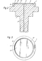
- the flow regulator comprises a body member 1 moulded from a plastics material and a second plastics moulding cap 2, hereinafter termed a diaphragm moulding, which is a push-fit on to the end of body member 1.
- the two mouldings 1, 2 enclose a chamber 3.
- Body member 1 has a raised central region 4 from which an outlet bore 5 extends through body member 1.
- Body member 1 is fastened to the exit of a container 6 by a nut 7 with an 0-ring seal 8 between the body member 1 and the interior surface of container 6. -
- Diaphragm moulding 2 has a rigid exterior flange 9, for engagement with body member 1, surrounding a disc-like diaphragm 10. Round the periphery 11 of the diaphragm 10, the moulding is of reduced thickness so that the diaphragm acts as a supported, rather than clamped, plate.
- a small diameter hole 12 forming the inlet to chamber 3 is bored through the diaphragm 10.
- the invention is further illustrated by the following Example in which apparatus of the type shown in Figures 1 to 3 was employed.
- Diaphragm moulding 2 had an overall diameter of 24.5 mm while the diaphragm 10, i.e. the portion within the line 11 of reduced thickness, had a diameter of 20 mm.
- the thickness of diaphragm 10 was 0.37 mm while, at the line 11 of reduced thickness, the thickness was 0.20 mm.
- the diaphragm mounding 2 was made from an oxymethylene polymer.
- the flow regulator was mounted as shown in Figure 1 to the inside of a container that could be pressurised.
- the container was charged with a liquid and the pressure applied thereto increased in stages.
- the volumetric flow rate at various gauge pressures was measured. This was repeated using diaphragm mouldings having holes of differing sizes. In each case the diaphragm had only one hole.
- the liquid was water while in another set the liquid was a solution of specific gravity 0.89 of a pesticide in an organic solvent and having a viscosity of 3.5 Pa.s. All experiments were performed at 20°C.
Applications Claiming Priority (2)
| Application Number | Priority Date | Filing Date | Title |
|---|---|---|---|
| GB8429770 | 1984-11-26 | ||
| GB848429770A GB8429770D0 (en) | 1984-11-26 | 1984-11-26 | Flow regulator |
Publications (2)
| Publication Number | Publication Date |
|---|---|
| EP0183425A2 true EP0183425A2 (de) | 1986-06-04 |
| EP0183425A3 EP0183425A3 (de) | 1988-01-07 |
Family
ID=10570253
Family Applications (1)
| Application Number | Title | Priority Date | Filing Date |
|---|---|---|---|
| EP85308210A Withdrawn EP0183425A3 (de) | 1984-11-26 | 1985-11-12 | Abflussregler |
Country Status (4)
| Country | Link |
|---|---|
| EP (1) | EP0183425A3 (de) |
| JP (1) | JPS61144474A (de) |
| AU (1) | AU5027185A (de) |
| GB (1) | GB8429770D0 (de) |
Cited By (3)
| Publication number | Priority date | Publication date | Assignee | Title |
|---|---|---|---|---|
| US5042697A (en) * | 1988-03-08 | 1991-08-27 | National Research Development Corporation | Pressure regulators |
| WO1994021938A1 (en) * | 1993-03-19 | 1994-09-29 | Cambridge Consultants Limited | Flow control valve |
| CN109433542A (zh) * | 2019-01-17 | 2019-03-08 | 上海威固化工制品有限公司 | 泡沫填缝剂喷枪 |
Citations (6)
| Publication number | Priority date | Publication date | Assignee | Title |
|---|---|---|---|---|
| US3523559A (en) * | 1968-05-17 | 1970-08-11 | Crane Co | Fluid flow control device |
| DE2553054A1 (de) * | 1974-12-02 | 1976-08-12 | Tor Harry Petterson | Austeiler zum intermittierenden abgeben eines aerosols |
| DE2704159A1 (de) * | 1976-02-02 | 1977-08-04 | Jean Cloup | Vorrichtung zur teilung eines fluessigkeitsstroms |
| DE2921561A1 (de) * | 1979-05-28 | 1980-12-11 | Regel Messtechnik Gmbh | Beatmungsventil |
| US4241757A (en) * | 1979-03-26 | 1980-12-30 | Dan Bron | Flow regulator |
| DE3150117A1 (de) * | 1981-12-18 | 1983-07-14 | Robert 7321 Albershausen Schönfeld | Durchflussmengenregler fuer fluessige und bzw. oder gasfoermige stoffe |
-
1984
- 1984-11-26 GB GB848429770A patent/GB8429770D0/en active Pending
-
1985
- 1985-11-12 EP EP85308210A patent/EP0183425A3/de not_active Withdrawn
- 1985-11-22 AU AU50271/85A patent/AU5027185A/en not_active Abandoned
- 1985-11-26 JP JP60265948A patent/JPS61144474A/ja active Pending
Patent Citations (6)
| Publication number | Priority date | Publication date | Assignee | Title |
|---|---|---|---|---|
| US3523559A (en) * | 1968-05-17 | 1970-08-11 | Crane Co | Fluid flow control device |
| DE2553054A1 (de) * | 1974-12-02 | 1976-08-12 | Tor Harry Petterson | Austeiler zum intermittierenden abgeben eines aerosols |
| DE2704159A1 (de) * | 1976-02-02 | 1977-08-04 | Jean Cloup | Vorrichtung zur teilung eines fluessigkeitsstroms |
| US4241757A (en) * | 1979-03-26 | 1980-12-30 | Dan Bron | Flow regulator |
| DE2921561A1 (de) * | 1979-05-28 | 1980-12-11 | Regel Messtechnik Gmbh | Beatmungsventil |
| DE3150117A1 (de) * | 1981-12-18 | 1983-07-14 | Robert 7321 Albershausen Schönfeld | Durchflussmengenregler fuer fluessige und bzw. oder gasfoermige stoffe |
Cited By (4)
| Publication number | Priority date | Publication date | Assignee | Title |
|---|---|---|---|---|
| US5042697A (en) * | 1988-03-08 | 1991-08-27 | National Research Development Corporation | Pressure regulators |
| WO1994021938A1 (en) * | 1993-03-19 | 1994-09-29 | Cambridge Consultants Limited | Flow control valve |
| CN109433542A (zh) * | 2019-01-17 | 2019-03-08 | 上海威固化工制品有限公司 | 泡沫填缝剂喷枪 |
| CN109433542B (zh) * | 2019-01-17 | 2024-01-30 | 山东桑莱斯新材料有限公司 | 泡沫填缝剂喷枪 |
Also Published As
| Publication number | Publication date |
|---|---|
| EP0183425A3 (de) | 1988-01-07 |
| AU5027185A (en) | 1986-06-05 |
| GB8429770D0 (en) | 1985-01-03 |
| JPS61144474A (ja) | 1986-07-02 |
Similar Documents
| Publication | Publication Date | Title |
|---|---|---|
| NO174379B (no) | Drivtrykkregulator med monteringshus | |
| EP0072091A1 (de) | Saugrückschlagventil | |
| US3357448A (en) | Constant flow valve | |
| EP0118049B1 (de) | Durchflussmengenregler | |
| CA2327903A1 (en) | Aerosol spray texturing device with deformable outlet member | |
| JPH0726720B2 (ja) | ガス加圧分配容器及びその分配装置 | |
| EP0183425A2 (de) | Abflussregler | |
| EP3378569A1 (de) | Spendervorrichtung | |
| US4328820A (en) | Constant-flow regulator for gravity-fed liquids | |
| US3478776A (en) | Pressure regulating device for fluid dispensing systems | |
| CA2250519A1 (en) | Precision liquid dispenser device | |
| JPH08507278A (ja) | 容器からの極低速流体分配装置 | |
| US4887639A (en) | Non-degrading pressure regulator | |
| US5819775A (en) | Low flow rate valve | |
| EP0133770A2 (de) | Abgabevorrichtung für Flüssigkeiten | |
| WO1999053388A1 (en) | Fluid regulator and improvements related thereto | |
| US4132362A (en) | Spray head | |
| US5725073A (en) | Fluid metering device and compressed air lubricator including same | |
| US3965934A (en) | Fluid regulating devices | |
| NL2023492B1 (en) | Pressure valve for a liquid | |
| WO2007028390A1 (en) | Device for automatic regulation of flow | |
| JPH10169894A (ja) | 圧縮空気注油器に関する改良 | |
| US4505298A (en) | Fluid dispensing valve assembly | |
| IE60193B1 (en) | "Thrust regulator comprising a mounting enclosure" | |
| US3082789A (en) | Flow control devices for mixing and/or dispensing apparatus |
Legal Events
| Date | Code | Title | Description |
|---|---|---|---|
| PUAI | Public reference made under article 153(3) epc to a published international application that has entered the european phase |
Free format text: ORIGINAL CODE: 0009012 |
|
| AK | Designated contracting states |
Kind code of ref document: A2 Designated state(s): AT BE CH DE FR GB IT LI LU NL SE |
|
| PUAL | Search report despatched |
Free format text: ORIGINAL CODE: 0009013 |
|
| AK | Designated contracting states |
Kind code of ref document: A3 Designated state(s): AT BE CH DE FR GB IT LI LU NL SE |
|
| STAA | Information on the status of an ep patent application or granted ep patent |
Free format text: STATUS: THE APPLICATION IS DEEMED TO BE WITHDRAWN |
|
| 18D | Application deemed to be withdrawn |
Effective date: 19871201 |
|
| RIN1 | Information on inventor provided before grant (corrected) |
Inventor name: CONNOLLY, ANTHONY Inventor name: BAXTER, WILLIAM RONALD STUART |