EP0183224A1 - Print head for an ink jet printer - Google Patents
Print head for an ink jet printer Download PDFInfo
- Publication number
- EP0183224A1 EP0183224A1 EP85114981A EP85114981A EP0183224A1 EP 0183224 A1 EP0183224 A1 EP 0183224A1 EP 85114981 A EP85114981 A EP 85114981A EP 85114981 A EP85114981 A EP 85114981A EP 0183224 A1 EP0183224 A1 EP 0183224A1
- Authority
- EP
- European Patent Office
- Prior art keywords
- plate
- ink
- channels
- channel
- outlet openings
- Prior art date
- Legal status (The legal status is an assumption and is not a legal conclusion. Google has not performed a legal analysis and makes no representation as to the accuracy of the status listed.)
- Granted
Links
Images


Classifications
-
- B—PERFORMING OPERATIONS; TRANSPORTING
- B41—PRINTING; LINING MACHINES; TYPEWRITERS; STAMPS
- B41J—TYPEWRITERS; SELECTIVE PRINTING MECHANISMS, i.e. MECHANISMS PRINTING OTHERWISE THAN FROM A FORME; CORRECTION OF TYPOGRAPHICAL ERRORS
- B41J2/00—Typewriters or selective printing mechanisms characterised by the printing or marking process for which they are designed
- B41J2/005—Typewriters or selective printing mechanisms characterised by the printing or marking process for which they are designed characterised by bringing liquid or particles selectively into contact with a printing material
- B41J2/01—Ink jet
- B41J2/135—Nozzles
- B41J2/14—Structure thereof only for on-demand ink jet heads
- B41J2/14201—Structure of print heads with piezoelectric elements
- B41J2/1429—Structure of print heads with piezoelectric elements of tubular type
-
- B—PERFORMING OPERATIONS; TRANSPORTING
- B41—PRINTING; LINING MACHINES; TYPEWRITERS; STAMPS
- B41J—TYPEWRITERS; SELECTIVE PRINTING MECHANISMS, i.e. MECHANISMS PRINTING OTHERWISE THAN FROM A FORME; CORRECTION OF TYPOGRAPHICAL ERRORS
- B41J2/00—Typewriters or selective printing mechanisms characterised by the printing or marking process for which they are designed
- B41J2/005—Typewriters or selective printing mechanisms characterised by the printing or marking process for which they are designed characterised by bringing liquid or particles selectively into contact with a printing material
- B41J2/01—Ink jet
- B41J2/135—Nozzles
- B41J2/14—Structure thereof only for on-demand ink jet heads
- B41J2002/14387—Front shooter
Definitions
- the invention relates to a writing head for ink writing devices according to the preamble of patent claim 1.
- the object of the invention is to provide a writing head for ink writing devices, the construction of which requires a few individual parts which can be produced with little effort, which can be assembled by simple assembly processes without additional reworking of the individual parts and which ensures a high level of functional reliability during operation
- the unit provided for the construction of the write head according to the invention and hereinafter referred to as a channel block, which comprises the ink channels arranged on a common carrier part and running parallel to one another, can in a simple manner, for. B. be produced as a molded plastic part.
- This unit is equipped with the piezotubes by simply plugging it onto the ink channels running parallel over its entire length.
- Contact is made with contact elements of a contact device which is preferably designed as a plastic plate with conductor tracks.
- the channel plate attached to one side of the channel block and the plate-shaped adhesive part provided for one exemplary embodiment can also preferably be prefabricated as an injection-molded part and assembled in a simple manner. The entire unit can finally be completely or partially cast.
- the channel plate represents the front end of the write head facing the writing point. It also serves as a plate-shaped holding part for receiving the free ends of the ink channels.
- the ink is supplied through the openings in the carrier part.
- the channel plate is attached to the rear surface of the carrier part without gaps and in an ink-tight manner.
- the plate-shaped holding part is additionally provided for the plug-in reception of the free ends of the ink channels, via which the ink supply is then also carried out characterized in the subclaims.
- FIG. 1 shows in perspective the essential parts of a write head necessary for understanding the invention.
- the arrangement shows a channel block, which consists of a carrier part 1, on which tubular ink channels 2 'are formed. It is an injection molded plastic part that can be manufactured as a single unit at low cost and with little effort.
- the parallel ink channels 2 end on the rear side of the carrier part 1 in openings 13. On the other side, in the example facing the, the ends of the ink channels 2 are free.
- This channel block is equipped with the piezo tubes 3. This is done by plugging the piezotubes 3 onto the ink channels 2.
- An adhesive can be used for fastening.
- a contact device 10 for example a plastic plate and provided with conductor tracks, the contact elements of which, in the example, contact springs 11 and 12, are placed on the piezo tubes 3 contact the contact layers.
- a plate-shaped holding part is provided for receiving the front free ends 4 of the ink channels 2.
- this holding part is realized by a channel plate 5, which has correspondingly shaped and arranged holes 6 in a layer plate 7 on the side facing the ink channels 2, in which the free ends 4 of the ink channels 2 are inserted.
- the channel plate 5 has ink outlet openings on the side facing the writing point, the spacing of which corresponds to the division grid provided for the writing operation.
- This part of the channel plate, namely the layer plate 9, thus corresponds to an orifice plate.
- transition channels are arranged in a middle layer plate 8 of the channel plate 5.
- a three-layer plate is used as the channel plate 5 in the exemplary embodiment shown here, in which the pluggable reception of the free ends 4 of the ink channels 2 in a first layer plate 7, the
- Transition channels for guiding the ink flow in a second layer plate 8 and the outlet openings of the write head are formed in a third layer plate 9. Details of this will be described later with reference to FIGS. 2 to 5.
- the write head constructed in the manner described can then z. B. with casting resin either completely or partially.
- a complete potting has the advantage that good damping of the print head is achieved. This is associated with a significant reduction in so-called crosstalk effects and an increase in the so-called spray frequency.
- a partial potting can be sufficient, whereby a significant weight reduction of the printhead is achieved, which also has a favorable effect in terms of its speed and the speed at which the printhead is moved
- the construction of a write head according to the invention does not require reworking of the individual parts. Rather, these can be prefabricated with little effort and assembled without observing special tolerance conditions.
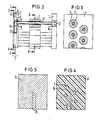
- Fig. 2 shows a sectional view of the write head structure according to Fig. 1.
- the ink channels 2 extend with their free ends 4 parallel to the front. They are encompassed over part of their length by the piezotubes 3 attached to them.
- the front free ends 4 of the ink channels 2 are inserted into openings 6 of the first layer plate 7 of the channel plate 5 and thus fixed.
- the middle layer plate 8 has recesses 14, via which the ink flow 2 is deflected and guided between the ink channels 2 and the outlet openings 15 in the third layer plate 9 takes place.
- the function of the third layer plate 9 can also be referred to as a nozzle plate. In the example according to FIG. 2, the contacting elements have no longer been shown.
- a contacting described with reference to FIG. 1 can be provided and that when a single piezo tube is actuated with a correspondingly polarized pulse in a manner known per se, this by changing its inside diameter a pressure pulse or a Pressure wave generated in the interior of the corresponding ink channel, which spreads to both sides and that a single droplet is ejected via the outlet opening 15 assigned to this ink channel.
- the ink channels 2 formed on the carrier part 1 are, in the example, as shown in FIG. 3 (section A-B), arranged in two rows offset from one another. They can be arranged at such a mutual distance that the piezo tubes can be fitted manually or automatically without problems.
- FIG. 4 and 5 show details of the channel plate 5, in each of which a section through the second layer plate 7 (section CD) and through the third layer plate 8 (section EF) is shown.
- the transition channels 14 In the middle or second layer plate 8 shown in FIG. 4 run the transition channels 14, which guide the ink flow between the ink channels 2 ending at the first layer plate 7 and the outlet openings 15 arranged in the third layer plate 9.
- the transition channels 14 can be formed as recesses in the second layer plate 8.
- the third layer plate 9 shown in FIG. 5 has the outlet openings 15 which are arranged in the division grid provided for the writing operation and which form a row in the example.
- the channel plate 5 can be made of ceramic, metal or plastic, the so-called ultrasonic welding process being used in particular for connecting plates made of plastic.
- the ink supply to the write head of the exemplary embodiment takes place via the openings 13 in the carrier part 1 of the channel block.
- These openings 13 are connected in a manner not shown here to an ink supply common for all ink channels 2 or for a certain number of ink channels, and this in turn is connected to an ink reservoir, from which, during operation of the write head under the action of the piezo tubes, the required through which Droplet ejection is used up.
- the channel plate on the rear surface of the carrier part, ie on the flat surface of the channel block.
- FIG. 6 An example of this is shown in FIG. 6.
- the channel block again consists of the carrier part 1 and the parallel ink channels 2 formed thereon. After inserting a contacting device (not shown here), the piezotubes 3 are plugged onto the ink channels 2. attached and contacted there.
- the channel plate 5 the structure of which can correspond to the previously described mounting mat, is fastened here in a spatula-free and ink-tight manner to the rear wall of the support part 1 of the channel block is, inserted via this cover plate 17, the ink supply system is connected, which in this case is common to all ink channels 2.
- it is advantageous to provide an additional support plate 18 on the front surface of the write head which in the region of the outlet openings 15 a corresponding recess 1. 9
- the entire arrangement can be completely or partially cast.
- a two-layer or a single-layer plate can also be used as the channel plate, as will be explained in the following with the aid of a few exemplary embodiments, various options being available for forming the transition channels.
- the transition channels 23 can be formed exclusively in the layer plate 21 of the channel plate 20 lying against the carrier part 1, or, as the embodiment according to FIG. 8 shows, a channel plate 24 be provided in which a part 25 of the transition channels is formed in the carrier part 1 and a second part 26 in the first layer plate 27.
- the outlet openings 15 are formed in the second layer plate 22 (FIG. 7) or 28 (FIG. 8) in accordance with the division provided for the writing operation.
- transition channels 30 and the outlet openings 15 can be arranged in the channel plate 29, as the exemplary embodiment according to FIG. 9 shows.
- the channel block and the channel plate in such a way that the outlet openings directly adjoin the ink channels.
- FIGS. 12 and 13 An example of this is shown in FIGS. 12 and 13.
- the ink channels 2 and the carrier part 1 form the unitary channel block, which can be created as a prefabricated unit.
- the ink channels 2 are arranged here along an oblique line with a pitch ta determined by the spacing of the piezo tubes 3. With their free ends 4, the ink channels 2 are inserted into the through openings 16 of the plate-shaped holding part 17.
- the connection to the ink supply system is also located on this side.
- the channel plate 31 fastened to the rear surface of the carrier part 1 represents the end of the write head facing the writing point.
- the channel plate 31 has the outlet openings 15 which have been worked out according to the position of the ink channels 2, that is to say also arranged along an oblique line, so that there is a vertical line Direction results in a pitch ts of the outlet openings 15, which is smaller than the pitch ta of the ink channels. In this embodiment, a transition channel is no longer required.
- characters are displayed in the writing mode in such a way that the writing head is moved in the direction of the arrow (FIG. 13), the height of the writing areas being determined by the inclination of the outlet openings 15 arranged along an oblique line.
Abstract
Die Erfindung betrifft einen Schreibkopf für Tintenschreibeinrichtungen mit röhrenförmigen Tintenkanälen (2), die über einen Teil ihrer Länge von individuell ansteuerbaren Piezoröhrchen (3) umfaßt sind und die zwischen einem Tintenversorgungsteil und den Austrittsöffnungen (15) des Schreibkopfes verlaufend angeordnet sind; die an einem Trägerteil (1) angeformten Tintenkanäle (2) bilden zusammen mit diesem einen vorfertigbaren Kanalblock; eine Kanalplatte (5) ist entweder an der Seite, an der die Tintenkanäle (2) frei enden,oder an der rückwärtigen Fläche des Trägerteils (1) befestigt; in einer Ausführung weist die Kanalplatte (5) eine Schichtplatte (7) mit Durchgangslöchern (6) auf, in die die mit dem Piezoröhrchen (3) bestückten freien Enden (4) der Tintenkanäle (2) einsteckbar sind; in weiteren Schichtplatten (8, 9) der Kanalplatte (5) sind Übergangskanäle (14) zur Führung des Tintenflusses und die Austrittsöffnungen (15) des Schreibkopfes ausgebildet Fig. 2.The invention relates to a writing head for ink writing devices with tubular ink channels (2) which are covered over part of their length by individually controllable piezo tubes (3) and which are arranged running between an ink supply part and the outlet openings (15) of the writing head; the ink channels (2) formed on a carrier part (1) form together with this a prefabricated channel block; a channel plate (5) is fixed either on the side where the ink channels (2) end freely or on the rear surface of the carrier part (1); In one embodiment, the channel plate (5) has a layer plate (7) with through holes (6) into which the free ends (4) of the ink channels (2) fitted with the piezo tube (3) can be inserted; Transition channels (14) for guiding the ink flow and the outlet openings (15) of the write head are formed in further layer plates (8, 9) of the channel plate (5), FIG. 2.
Description
Die Erfindung betrifft einen Schreibkopf für Tintenschreibeinrichtungen gemäß dem Oberbegriff des Patentanspruches 1.The invention relates to a writing head for ink writing devices according to the preamble of patent claim 1.
Zum Aufbau von Schreibköpfen für Tintenschreibeinrichtungen ist es bekannt (DE-PS 2543451), eine vormontierte, Formnadeln und röhrenförmige Piezoelemente enthaltende Einheit zu vergießen, wobei nach dem Entfernen der Formnadeln im Schreibkopf die Tintenkanäle entstehen. Die Tintenkanäle sind an dem der Schreibstelle zugewandten Ende mit einer Düsenplatte abgeschlossen. Am anderen Ende der Tintenkanäle stehen diese mit einem Tintenversorgungssystem in Verbindung. Der damit verbundene Fertigungsaufwand ist relativ groß und erfordert ein hohes Maß an manueller Tätigkeit insbesondere stellt die Einhaltung sehr enger Toleranzen hohe Anforderungen, was häufig zu aufwendigen Nachbehandlungen der Einzelteile führt.For the construction of writing heads for ink writing devices, it is known (DE-PS 25 4 3 4 5 1 ) to shed a preassembled unit containing molding needles and tubular piezo elements, the ink channels being formed in the writing head after removal of the molding needles. The ink channels are closed at the end facing the writing point with a nozzle plate. At the other end of the ink channels, these are connected to an ink supply system. The associated manufacturing effort is relatively large and requires a high degree of manual activity, in particular, the adherence to very tight tolerances places high demands, which often leads to costly post-treatment of the individual parts.
Zur Reduzierung des Aufwandes ist es weiterhin bekannt (DE-OS 3 234 408), die Tintenkanäle und die diesen zugeordneten Piezoröhrchen zu einer sogenannten Piezorohrgruppe zusammenzufassen. Die Tintenkanäle sind dabei fächerförmig angeordnet und verlaufen von einem gemeinsamen Steg ausgehend konvergierend nach vorne, wo sie in einer vorderen Kegelfläche zusammengefaßt sind. Die Herstellung einer derartigen Piezorohrgruppe ist vor allem wegen der sehr engen Teilung der Tintenkanäle am vorderen Bereich der Piezorohrgruppe nicht einfach; weiterhin ist auch zur Justierung der Piezoröhrchen, die in die Einheit mit einbezogen sind, ein beträchtlicher Aufwand, erforderlich.To reduce the effort, it is also known (DE-OS 3 234 408) to combine the ink channels and the piezo tubes assigned to them to form a so-called piezo tube group. The ink channels are arranged in a fan shape and, starting from a common web, converge to the front, where they are combined in a front conical surface. The production of such a piezo tube group is not easy, above all because of the very narrow division of the ink channels at the front area of the piezo tube group; furthermore, considerable effort is required to adjust the piezo tubes that are included in the unit.
Aufgabe der Erfindung ist es, einen Schreibkopf für Tintenschreibeinrichtungen zu schaffen, zu dessen Aufbau wenige,aufwandsarm herstellbare Einzelteile benötigt werden, die durch einfache Montagevorgänge ohne zusätzliche Nachbearbeitung der Einzelteile zusammengefügt werden können und der im Betrieb eine hohe Funktionssicherheit gewährleistetThe object of the invention is to provide a writing head for ink writing devices, the construction of which requires a few individual parts which can be produced with little effort, which can be assembled by simple assembly processes without additional reworking of the individual parts and which ensures a high level of functional reliability during operation
Diese Aufgabe wird mit den kennzeichnenden Merkmalen des Patentanspruches 1 gelöst.This object is achieved with the characterizing features of patent claim 1.
Die für den erfindungsgemäßen Aufbau des Schreibkopfes vorgesehene und im folgenden als Kanalblock bezeichnete Einheit, die die an einem gemeinsamen Trägerteil angeordneten, parallel zueinander verlaufenden Tintenkanäle umfaßt, kann in einfacher Weise z. B. als Kunststoffspritzteil hergestellt werden. Die Bestückung dieser Einheit mit den Piezoröhrchen geschieht durch einfaches Aufstecken auf die,über ihre gesamte Länge parallel verlaufenden Tintenkanäle. Die Kontaktierung geschieht mit Kontaktelementen einer vorzugsweise als Kunststoffplatte mit Leiterbahnen ausgeführten Kontaktvorrichtung. Auch die an einer Seite des Kanalblocks befestgte Kanalplatte sowie das für ein Ausführungsbeispiel vorgesehene plattenförmige Hafteteil kann vorzugsweise als Spritzteil vorgefertigt und in einfacher Weise montiert werden. Die gesamte Einheit Kann schließlich vollständig oder teilweise vergossen werden.The unit provided for the construction of the write head according to the invention and hereinafter referred to as a channel block, which comprises the ink channels arranged on a common carrier part and running parallel to one another, can in a simple manner, for. B. be produced as a molded plastic part. This unit is equipped with the piezotubes by simply plugging it onto the ink channels running parallel over its entire length. Contact is made with contact elements of a contact device which is preferably designed as a plastic plate with conductor tracks. The channel plate attached to one side of the channel block and the plate-shaped adhesive part provided for one exemplary embodiment can also preferably be prefabricated as an injection-molded part and assembled in a simple manner. The entire unit can finally be completely or partially cast.
In einer Ausführungsform der Erfindung stellt die Kanalplatte den der Schreibstelle zugewandten vorderen Abschluß des Schreibkopfes dar. Sie dient zugleich auch als plattenförmiges Halteteil zur Aufnahme der freien Enden der Tintenkanäle. In diesem Falle erfolgt die Tintenversorgung über die Öffnungen im Trägerteil. Gemäß einer anderen Ausführungsform ist die Kanalplatte an der rückwärtigen Fläche des Trägerteils spaltenfrei und tintendicht befestigt In diesem Falle ist das plattenförmige Halteteil zur steckbaren Aufnahme der freien Enden der Tintenkanäle zusätzlich vorgesehen, über das dann auch die Tintenversorgung erfolgt Weitere im Rahmen der Erfindung liegende Ausgestaltungen sind in den Unteransprüchen gekennzeichnet.In one embodiment of the invention, the channel plate represents the front end of the write head facing the writing point. It also serves as a plate-shaped holding part for receiving the free ends of the ink channels. In this case, the ink is supplied through the openings in the carrier part. According to another embodiment, the channel plate is attached to the rear surface of the carrier part without gaps and in an ink-tight manner. In this case, the plate-shaped holding part is additionally provided for the plug-in reception of the free ends of the ink channels, via which the ink supply is then also carried out characterized in the subclaims.
Einzelheiten der Erfindung werden im folgenden unter Bezugnahme auf die Zeichnungen näher erläutert. Dort zeigen
- Fig. 1 den Aufbau eines Schreibkopfes nach der Erfindung in perspektiviacher Darstellung,
- Fig. 2 bis Fig. 5 Einzelheiten der Anordnung nach Fig. 1 in verschiedenen Schnittdarstellungen,
- Fig. 6 eine Ausgestaltung der Erfindung, bei der die Kanalplatte an der rückwärtigen Fläche des Halteteiles befestigt ist und
- Fig. 7 bis Fig. 12 einige ausgestaltende Details der Anordnung nach Fig. 6.
- 1 is a perspective view of the structure of a write head according to the invention,
- 2 to FIG. 5 details of the arrangement of FIG. 1 in different sectional views,
- Fig. 6 shows an embodiment of the invention in which the channel plate is attached to the rear surface of the holding part and
- 7 to FIG. 1 2 some design details of the arrangement according to FIG. 6.
Das Ausführungsbeispiel nach Fig. 1 zeigt in perspektivischer Darstellung die wesentlichen zum Verständnis der Erfindung erforderlichen Teile eines Schreibkopfes. Die Anordnung zeigt einen Kanalblock, der aus einem Trägerteil 1 besteht, an dem röhrenförmige Tintenkanäle 2' angeformt sind. Es handelt sich dabei um ein Kunststaffspritzteil, das als eine Einheit kostengünstig einfach und aufwandsarm hergestellt werden kann. Die parallel verlaufenden Tintenkanäle 2 enden auf der rückwärtigen Seite des Trägerteiles 1 in Öffnungen 13. Auf der anderen Seite, im Beispiel nach vom weisend, sind die Enden der Tintenkanäle 2 frei. Dieser Kanalblock wird mit den Piezoröhrchen 3 bestückt. Das geschieht durch Aufstecken der Piezoröhrchen 3 auf die Tintenkanäle 2. Zur Befestigung kann ein Kleber verwendet werden. Zur Kontaktierung der Piezoröhrchen 3, die wie bekannt mit einer inneren und einer äußeren Kontaktschicht versehen sind, ist es vorteilhaft eine beispielsweise als Kunststoffplatte ausgebildete und mit Leiterbahnen versehene Kontaktvorrichtung 10 vorzusehen, deren Kontaktelemente, im Beispiel Kontaktfedern 11 und 12, beim Aufstecken auf die Piezoröhrchen 3 an die Kontaktschichten kontaktieren.The embodiment of FIG. 1 shows in perspective the essential parts of a write head necessary for understanding the invention. The arrangement shows a channel block, which consists of a carrier part 1, on which tubular ink channels 2 'are formed. It is an injection molded plastic part that can be manufactured as a single unit at low cost and with little effort. The
Zur Aufnahme der vorderen freien Enden 4 der Tintenkanäle 2 ist ein plattenförmiges Halteteil vorgesehen. Im Ausführungs beispiel nach Fig. 1 ist dieses Halteteil durch eine Kanalplatte 5 realisiert, die in einer Schichtplatte 7 auf der den Tintenkanälen 2 zugewandten Seite entsprechend geformte und angeordnete Löcher 6 aufweist, In diese werden die freien Enden 4 der Tintenkanäle 2 eingesteckt. Die Kanalplatte 5 weist auf der der Schreibstelle zugewandten Seite Tintenaustrittsöffnungen auf, deren Abstand dem für den Schreibbetrieb vorgesehenen Teiiungsraster entsprechen. Dieser Teil der Kanalplatte, nämlich die Schichtpiatte 9, entspricht also emer Düsenplatte. Da das Teilungsraster in der Regel enger ist als die Anordnung der Tintenkanäle 2 im Kanalblock, ist zwischen den Aufnahmeöffnungen 6 für die Tintenkanäle und den Austrittsöffnungen in der Schichtplatte 9 eine Umlenkung für den Tintenfluß vorzusehen. Im Ausführungsbeispiel sind dazu Übergangskanäle in einer mittleren Schichtplatte 8 der Kanalplatte 5 angeordnet Als Kanalplatte 5 wird in dem hier dargestellten Ausführungsbeispiel eine Dreischichtplatte verwendet, bei der die steckbare Aufnahme der freien Enden 4 der Tintenkanäle 2 in einer ersten Schichtplatte 7, dieA plate-shaped holding part is provided for receiving the front free ends 4 of the
ÜbergangskanäJe zur Führung des Tintenflusses in einer zweiten Schichtplatte 8 und die Austrttsöffnungen des Schreibkopfes in einer dritten Schichtplatte 9 ausgebildet sind. Einzelheiten dazu werden später unter Bezugnahme auf die Fig. 2 bis 5 beschrieben.Transition channels for guiding the ink flow in a
Der in der beschriebenen Weise aufgebaute Schreibkopf kann anschließend z. B. mit Gießharz entweder vollständig oder teilweise vergossen werden. Ein vollständiges Vergießen hat den Vorteil, daß damit eine gute Dämpfung des Schreibkopfes erreicht wird. Damit ist eine wesentliche Reduzierung von sogenannten Nebensprecheffekten sowie eine Erhöhung der sogenannten Spritzfrequenz verbunden. Für Schreibköpfe, bei denen diese Forderungen nicht sehr im Vordergrund stehen, kann ein teilweises Vergießen ausreichend sein, wodurch eine deutliche Gewichtsreduzierung des Schreibkopfes erreicht wird, was sich auch günstig im Hinblick auf dessen Antneb und der Geschwindigkeit, mit der der Schreibkopf bewegt wird, auswirkt In jedem Falle erfordert der Aufbau eines Schreibkopfes nach der Erfindung keine Nacharbeit der einzelnen Teile. Diese können vielmehr aufwandsarm vorgefertigt und ohne Beachtung spezieller Toleranzbedingungen zusammengefügt werden.The write head constructed in the manner described can then z. B. with casting resin either completely or partially. A complete potting has the advantage that good damping of the print head is achieved. This is associated with a significant reduction in so-called crosstalk effects and an increase in the so-called spray frequency. For printheads where these requirements are not very important, a partial potting can be sufficient, whereby a significant weight reduction of the printhead is achieved, which also has a favorable effect in terms of its speed and the speed at which the printhead is moved In any case, the construction of a write head according to the invention does not require reworking of the individual parts. Rather, these can be prefabricated with little effort and assembled without observing special tolerance conditions.
Fig. 2 zeigt in einer Schnittdarstellung den Schreibkopfaufbau nach Fig. 1. Vom Trägerteil 1 ausgehend erstrecken sich die Tintenkanäle 2 mit ihren freien Enden 4 parallel verlaufend nach vorne. Über einen Teil ihrer Länge sind sie von den auf sie aufgesteckten Piezoröhrchen 3 umfaßt. Die vorderen freien Enden 4 der Tintenkanäle 2 sind in Öffnungen 6 der ersten Schichtplatte 7 der Kanalplatte 5 eingesteckt und damit fixiert Die mittlere Schichtplatte 8 weist Ausnehmungen 14 auf, über die eine Umlenkung und Führung des Tintenflusses zwischen den Tintenkanälen 2 und den Austrittsöffnungen 15 in der dritten Schichtplatte 9 stattfindet. Die dritte Schichtplatte 9 kann von ihrer Funktion her auch als Düsenplatte bezeichnet werden. Im Beispiel nach Fig. 2 sind die Kontaktierungselemente nicht mehr dargestellt worden. Es ist jedoch ohne weiteres einzusehen, daß eine anhand von Fig. 1 beschriebene Kontaktierung vorgesehen sein kann und daß dann, wenn in an sich bekannter Weise ein einzelnes Piezoröhrchen mit einem entsprechend gepolten Impuls angesteuert wird, dieses durch eine Veränderung seines Innendurchmessers einen Druckimpuls oder eine Druckwelle im Inneren des entsprechenden Tintenkanals erzeugt, die sich nach beiden Seiten hin ausbreitet und daß über die diesem Tintenkanal zugeordneten Austrittsöffnung 15 ein Einzeltröpfchen ausgestossen wird.Fig. 2 shows a sectional view of the write head structure according to Fig. 1. Starting from the carrier part 1, the
Die am Trägerteil 1 angeformten Tintenkanäle 2 sind im Beispiel, wie Fig. 3 (Schnitt A-B) zeigt, in zwei Reihen zueinander versetzt angeordnet Sie können in einem solchen gegenseitigen Abstand angeordnet sein, daß eine manuelle oder automatische Bestückung mit den Piezoröhrchen problemlos erfolgen kann.The
Einzelheiten der Kanalplatte 5 zeigen die Fig. 4 und 5, in denen jeweils ein Schnitt durch die zweite Schichtplatte 7 (Schnitt C-D) und durch die dritte Schichtplatte 8 (Schnitt E-F) dargestellt ist In der in Fig. 4 dargestellten mittleren oder zweiten Schichtplatte 8 verlaufen die Übergangskanäle 14, die den Tintenfluß zwischen den an der ersten Schichtplatte 7 endenden Tintenkanälen 2 und den in der dritten Schichtplatte 9 angeordneten Austrittsöffnungen 15 führen. Die Übergangskanäle 14 können als Ausnehmungen in der zweiten Schichtplatte 8 ausgebildet sein. Die in Fig. 5 dargestellte dritte Schichtplatte 9 weist die im für den Schreibbetrieb vorgesehenen Teilungsraster angeordneten Austrittsöffnungen 15 auf, die im Beispiel eine Reihe bilden. Die Kanalplatte 5 kann aus Keramik, aus Metall oder aus Kunststoff aufgebaut sein, wobei insbesondere zur Verbindung von aus Kunststoff hergestellten Platten das sogenannte Uftraschallschweißverfahren Anwendung finden kann.4 and 5 show details of the channel plate 5, in each of which a section through the second layer plate 7 (section CD) and through the third layer plate 8 (section EF) is shown. In the middle or
Die Tintenversorgung des Schreibkopfes des Ausführungsbeispiels erfolgt über die Öffnungen 13 im Trägerteil 1 des Kanalblocks. Diese Öffnungen 13 sind in hier nicht dargestellter Weise an eine für alle Tintenkanäle 2 oder für eine bestimmte Zahl von Tintenkanälen gemeinsamen Tintenzuführung angeschlossen und diese wiederum ist mit einem Tintenvorratsbehälter verbunden, aus dem im Betrieb des Schreibkopfes unter der Wirkung der Piezoröhrchen die erforderliche, durch den Tröpfchenausstoß verbrauchte Tintenmenge nachgesaugt wird.The ink supply to the write head of the exemplary embodiment takes place via the
Bei dem beschriebenen Ausführungsbeispiel ist davon ausgegangen worden, daß die freien Enden der Tintenkanäle mit der Kanalplatte abgeschlossen werden. Im Rahmen der Erfindung ist es jedoch auch möglich, die Kanalplatte an der rückwärtigen Fläche des Trägerteils, d. h. an der planen Fläche des KanaJblockes anzuordnen. Ein Beispiel dafür zeigt Fig. 6. Der Kanalblock besteht wiederum aus dem Trägerteil 1 und den daran angeformten parallel verlaufenden Tintenkanälen 2. Nach dem Einsetzen einer hier nicht dargestellten Kontaktierungsvorrichtung werden die Piezoröhrchen 3 auf die Tintenkanäle 2 aufgesteckt. dort befestigt und kontaktiert. Die Kanalplatte 5, deren Aufbau der vorher beschriebenen Aufbauptatte entsprechen kann, ist hier spattenfrei und tintendicht an der Rückwand des Trägerteils 1 des Kanalblocks befestigt Die freien Enden 4 der Tintenkanäle 2 sind in Öffnungen 16 eines plattenförmigen Halteelements, das im folgenden als Deckplatte 17,bezeichnet wird, eingesteckt Über diese Deck- ,platte 17 ist das Tintenversorgungssystem angeschlossen, das in diesem Falle für alle Tintenkanäle 2 gemeinsame ist. Die Verbindung zwischen den Tintenkanälen 2 und der Tintenversorgung, die hier nicht dargestellt ist, erfolgt über die Öffnungen 16 in der Deckplatte 17. Um die Festigkeit der gesamten Anordnung zu erhöhen, ist es vorteilhaft, an der vorderen Fläche des Schreibkopfes eine zusätzliche Abstützplatte 18 vorzusehen, die im Bereich der Austrittsöffnungen 15 eine entsprechende Aussparung 19 aufweist. Die gesamte Anordnung kann, wie anhand von Fig. 1 bereits angegeben, vollständig oder teilweise vergossen werden.In the described embodiment, it has been assumed that the free ends of the ink channels are closed with the channel plate. Within the scope of the invention, however, it is also possible to arrange the channel plate on the rear surface of the carrier part, ie on the flat surface of the channel block. An example of this is shown in FIG. 6. The channel block again consists of the carrier part 1 and the
Als Kanalplatte kann auch, wie im folgenden anhand einiger Ausführungsbeispiele erläutert wird, eine Zwei- oder eine Einschichtplatte verwendet werden, wobei sich für die Ausbildung der Übergangskanäle verschiedene Möglichkeiten bieten.A two-layer or a single-layer plate can also be used as the channel plate, as will be explained in the following with the aid of a few exemplary embodiments, various options being available for forming the transition channels.
Bei Verwendung einer Zweischichtplatte können, wie die Ausgestaltung nach Fig. 7 zeigt, die Übergangskanäle 23 ausschließlich in der an das Trägerteil 1 anliegenden Schichtplatte 21 der Kanalplatte 20 ausgebildet sein, oder es kann, wie die Ausgestaltung nach Fig. 8 zeigt, eine Kanalplatte 24 vorgesehen sein, in der ein Teil 25 der Übergangskanäle im Trägerteil 1 und ein zweiter Teil 26 in der ersten Schichtplatte 27 ausgebildet ist. Die Austrittsöffnungen 15 sind in be;1en Fällen entsprechend der für den Schreibbetrieb vorgesehenen Teilung jeweils in der zweiten Schichtplatte 22 (Fig. 7) bzw. 28 (Fig. 8) ausgebildet.When using a two-layer plate, as shown in the embodiment according to FIG. 7, the
Bei Verwendung einer Einschichtplatte können, wie das Ausführungsbeispiel nach Fig. 9 zeigt, die Übergangskanäle 30 und die Austrittsöffnungen 15 in der Kanalplatte 29 angeordnet sein. Es ist aber auch möglich, wie Fig. 10 zeigt, im Trägerteil 1 Übergangskanäle 32 auszubilden und eine Kanalplatte 31 vorzusehen, die nur die Austrittsöffnungen 15 enthält.When using a single-layer plate, the
In einer weiteren Ausgestaltung kann es, wie Fig. 11 zeigt, vorteilhaft sein, bei im Trägerteil 1 angeordneten Tintenkanälen 2, zwei Platten 33, 31 mit unterschiedlich großen Öffnungen zu verwenden, die zudem aus unterschiedlichen Materialien bestehen können, wobei die Möglichkeit besteht, daß die eine Düsenplatte entsprechend Platte 31 nicht fest verbunden ist und entfernt werden kann.In a further embodiment, it can be advantageous, as shown in FIG. 11, to use two
Im Rahmen der Erfindung liegt es schließlich auch, den Kanalblock und die Kanalplatte derart zu gestalten, daß die Austrittsöffnungen sich unmittelbar an die Tintenkanäle anschließen. Ein Beispiel dafür zeigen die Fig. 12 und 13. Wiederum bilden die Tintenkanäle 2 und das Trägerteil 1 den einheitlichen Kanalblock, der als vorgefertigte Einheit erstellt werden kann. Die Tintenkanäle 2 sind hier entlang einer schrägen Linie mit einem durch den Abstand der Piezoröhrchen 3 bestimmten Teilungsabstand ta angeordnet. Mit ihren freien Enden 4 sind die Tintenkanäle 2 in die Durchgangsöffnungen 16 des plattenförmigen Halteteils 17 eingesteckt An dieser Seite befindet sich auch die Verbindung mit dem Tintenversorgungssystem. Die an der rückwärtigen Fläche des Trägerteils 1 befestigte Kanalplatte 31 stellt das der Schreibstelle zugewandte Ende des Schreibkopfes dar. Die Kanalplatte 31 weist die entsprechend der Lage der Tintenkanäle 2 ausgearbeiteten, also ebenfalls entlang einer schrägen Linie angeordneten Austrittsöffnungen 15 auf, so daß sich in vertikaler Richtung ein Teilungsabstand ts der Austrittsöffnungen 15 ergibt, der kleiner ist als der Teilungsabstand ta der Tintenkanäle. Bei dieser Ausgestaltung ist ein Übergangskanal nicht mehr erforderlich. Wie an sich bekannt erfolgt die Darstellung von Zeichen im Schreibbetrieb in diesem Falle in der Weise, daß der Schreibkopf in Pfeilrichtung (Fig. 13) bewegt wird, wobei die Höhe der Schriftreichen durch die Neigung der entlang einer schrägen Linie angeordneten Austrittsöffnungen 15 bestimmt ist.Finally, it is also within the scope of the invention to design the channel block and the channel plate in such a way that the outlet openings directly adjoin the ink channels. An example of this is shown in FIGS. 12 and 13. Again, the
Claims (11)
Applications Claiming Priority (2)
| Application Number | Priority Date | Filing Date | Title |
|---|---|---|---|
| DE3443579 | 1984-11-29 | ||
| DE3443579 | 1984-11-29 |
Publications (2)
| Publication Number | Publication Date |
|---|---|
| EP0183224A1 true EP0183224A1 (en) | 1986-06-04 |
| EP0183224B1 EP0183224B1 (en) | 1989-10-04 |
Family
ID=6251501
Family Applications (1)
| Application Number | Title | Priority Date | Filing Date |
|---|---|---|---|
| EP85114981A Expired EP0183224B1 (en) | 1984-11-29 | 1985-11-26 | Print head for an ink jet printer |
Country Status (4)
| Country | Link |
|---|---|
| US (1) | US4665409A (en) |
| EP (1) | EP0183224B1 (en) |
| JP (1) | JPS61134264A (en) |
| DE (1) | DE3573391D1 (en) |
Cited By (2)
| Publication number | Priority date | Publication date | Assignee | Title |
|---|---|---|---|---|
| EP0260884A2 (en) * | 1986-09-17 | 1988-03-23 | Lexmark International, Inc. | Print head for drop-on-demand ink jet printing apparatus |
| EP0691205A3 (en) * | 1994-07-05 | 1996-03-20 | Francotyp Postalia Gmbh | Modular ink jet print head |
Families Citing this family (15)
| Publication number | Priority date | Publication date | Assignee | Title |
|---|---|---|---|---|
| USRE35737E (en) * | 1986-07-09 | 1998-02-24 | Vidoejet Systems International, Inc. | Accoustically soft ink jet nozzle assembly |
| US4812859A (en) * | 1987-09-17 | 1989-03-14 | Hewlett-Packard Company | Multi-chamber ink jet recording head for color use |
| JPH02274559A (en) * | 1989-04-18 | 1990-11-08 | Komori Corp | Head of image printer |
| US5087930A (en) * | 1989-11-01 | 1992-02-11 | Tektronix, Inc. | Drop-on-demand ink jet print head |
| IL97034A (en) * | 1991-01-24 | 1994-07-31 | Carmon Amiram | Ink jet print heads utilizing fused silicon microcapillary ink channels |
| US5473354A (en) * | 1994-05-26 | 1995-12-05 | Hewlett-Packard Company | Ink-delivery apparatus |
| DE10032281A1 (en) | 2000-07-03 | 2002-01-17 | Heidelberger Druckmasch Ag | Emulsion control method for printing press, involves producing oscillations at frequency corresponding to that of ultrasound into emulsion formed on roller |
| US6955417B2 (en) * | 2002-03-28 | 2005-10-18 | Fuji Photo Film Co., Ltd. | Inkjet recording head and inkjet printer |
| US7052117B2 (en) | 2002-07-03 | 2006-05-30 | Dimatix, Inc. | Printhead having a thin pre-fired piezoelectric layer |
| US7281778B2 (en) | 2004-03-15 | 2007-10-16 | Fujifilm Dimatix, Inc. | High frequency droplet ejection device and method |
| US8491076B2 (en) | 2004-03-15 | 2013-07-23 | Fujifilm Dimatix, Inc. | Fluid droplet ejection devices and methods |
| KR20070087223A (en) | 2004-12-30 | 2007-08-27 | 후지필름 디마틱스, 인크. | Ink jet printing |
| US7988247B2 (en) | 2007-01-11 | 2011-08-02 | Fujifilm Dimatix, Inc. | Ejection of drops having variable drop size from an ink jet printer |
| US9464213B2 (en) | 2014-12-30 | 2016-10-11 | Jamal Taha | Surgical glove tape |
| US10004282B2 (en) | 2014-12-30 | 2018-06-26 | Jamal Taha | Surgical glove tape |
Citations (1)
| Publication number | Priority date | Publication date | Assignee | Title |
|---|---|---|---|---|
| EP0063637A2 (en) * | 1981-04-29 | 1982-11-03 | Siemens Aktiengesellschaft | Ink jet recording head with cylindrical ink channels |
Family Cites Families (7)
| Publication number | Priority date | Publication date | Assignee | Title |
|---|---|---|---|---|
| US4158847A (en) * | 1975-09-09 | 1979-06-19 | Siemens Aktiengesellschaft | Piezoelectric operated printer head for ink-operated mosaic printer units |
| JPS594309B2 (en) * | 1979-01-31 | 1984-01-28 | 富士通株式会社 | inkjet recording device |
| JPS55117665A (en) * | 1979-03-01 | 1980-09-10 | Ricoh Co Ltd | Ink jet integrated head |
| JPS55130783A (en) * | 1979-03-30 | 1980-10-09 | Canon Inc | Recording head |
| IT1144625B (en) * | 1981-08-04 | 1986-10-29 | Olivetti & Co Spa | INK JET POINTER PRINTER |
| US4418356A (en) * | 1981-09-23 | 1983-11-29 | Ncr Corporation | Ink jet print head |
| DE3234408C2 (en) * | 1982-09-16 | 1986-01-09 | Siemens AG, 1000 Berlin und 8000 München | Write head with piezoelectric drive elements for ink writing devices |
-
1985
- 1985-11-15 US US06/798,306 patent/US4665409A/en not_active Expired - Lifetime
- 1985-11-26 EP EP85114981A patent/EP0183224B1/en not_active Expired
- 1985-11-26 DE DE8585114981T patent/DE3573391D1/en not_active Expired
- 1985-11-28 JP JP60266290A patent/JPS61134264A/en active Pending
Patent Citations (1)
| Publication number | Priority date | Publication date | Assignee | Title |
|---|---|---|---|---|
| EP0063637A2 (en) * | 1981-04-29 | 1982-11-03 | Siemens Aktiengesellschaft | Ink jet recording head with cylindrical ink channels |
Non-Patent Citations (3)
| Title |
|---|
| PATENTS ABSTRACTS OF JAPAN, Band 4, Nr. 150 (M-37)[632], 22. Oktober 1980; & JP - A - 55 101 466 (FUJITSU K.K.) 02.08.1980 * |
| PATENTS ABSTRACTS OF JAPAN, Band 4, Nr. 167 (M-42)[649], 19. November 1980; & JP - A - 55 117 666 (RICOH K.K.) 10.09.1980 * |
| PATENTS ABSTRACTS OF JAPAN, Band 4, Nr. 183 (M-47)[665], 17. Dezember 1980; & JP - A - 55 130 783 (CANON K.K.) 09.10.1980 * |
Cited By (3)
| Publication number | Priority date | Publication date | Assignee | Title |
|---|---|---|---|---|
| EP0260884A2 (en) * | 1986-09-17 | 1988-03-23 | Lexmark International, Inc. | Print head for drop-on-demand ink jet printing apparatus |
| EP0260884A3 (en) * | 1986-09-17 | 1989-05-17 | International Business Machines Corporation | Print head for drop-on-demand ink jet printing apparatus |
| EP0691205A3 (en) * | 1994-07-05 | 1996-03-20 | Francotyp Postalia Gmbh | Modular ink jet print head |
Also Published As
| Publication number | Publication date |
|---|---|
| JPS61134264A (en) | 1986-06-21 |
| DE3573391D1 (en) | 1989-11-09 |
| US4665409A (en) | 1987-05-12 |
| EP0183224B1 (en) | 1989-10-04 |
Similar Documents
| Publication | Publication Date | Title |
|---|---|---|
| EP0183224A1 (en) | Print head for an ink jet printer | |
| DE2543451C2 (en) | Piezoelectrically operated writing head for ink mosaic writing devices | |
| EP0128456B1 (en) | Piezoelectrically actuated writing head | |
| DE3248087A1 (en) | LIQUID JET HEAD | |
| DE2703320C2 (en) | Droplet jet recording device | |
| EP0121894B1 (en) | Piezoelectrically operated write head for ink mosaic recording devices | |
| DE3445720A1 (en) | ARRANGEMENT FOR THE EMISSION OF SINGLE DROPLES FROM THE SPLIT OPENINGS OF AN INK WRITING HEAD | |
| DE69824019T2 (en) | DROPLET PRECIPITATION DEVICE | |
| EP0135197A1 (en) | Droplets generating device for ink-printer units | |
| DE3246839A1 (en) | WRITING HEAD FOR A PULSE JET INK RECORDER | |
| DE2532796C2 (en) | Device for droplet excitation with the aid of traveling wave excitation for an ink droplet writer | |
| DE3018334C2 (en) | ||
| DE3006726C2 (en) | Ink writing device | |
| DE3820082A1 (en) | Ink jet print head | |
| EP0063637B1 (en) | Ink jet recording head with cylindrical ink channels | |
| EP0057956B1 (en) | Writing head for an ink jet printer | |
| DE69913079T2 (en) | Piezoelectric vibrator unit, its manufacturing method and an ink jet recording head containing this vibrator unit | |
| DE69833978T2 (en) | Droplet recorder and manufacturing method therefor | |
| EP0040784A2 (en) | Arrangement for a print head in a matrix ink jet writing device | |
| EP0131704B1 (en) | Liquid droplets recording device | |
| EP0326568B1 (en) | Multilayer ink writing head | |
| DE69818121T2 (en) | Inkjet printhead | |
| DE3917434C2 (en) | ||
| DE3337495C2 (en) | Valve device for an ink mosaic print head | |
| DE3710654A1 (en) | Ink jet print head of multi-layer construction |
Legal Events
| Date | Code | Title | Description |
|---|---|---|---|
| PUAI | Public reference made under article 153(3) epc to a published international application that has entered the european phase |
Free format text: ORIGINAL CODE: 0009012 |
|
| 17P | Request for examination filed |
Effective date: 19860226 |
|
| AK | Designated contracting states |
Kind code of ref document: A1 Designated state(s): CH DE FR GB IT LI NL SE |
|
| 17Q | First examination report despatched |
Effective date: 19870729 |
|
| GRAA | (expected) grant |
Free format text: ORIGINAL CODE: 0009210 |
|
| AK | Designated contracting states |
Kind code of ref document: B1 Designated state(s): CH DE FR GB IT LI NL SE |
|
| PG25 | Lapsed in a contracting state [announced via postgrant information from national office to epo] |
Ref country code: SE Effective date: 19891004 Ref country code: NL Effective date: 19891004 |
|
| REF | Corresponds to: |
Ref document number: 3573391 Country of ref document: DE Date of ref document: 19891109 |
|
| ET | Fr: translation filed | ||
| PGFP | Annual fee paid to national office [announced via postgrant information from national office to epo] |
Ref country code: FR Payment date: 19891124 Year of fee payment: 5 |
|
| ITTA | It: last paid annual fee | ||
| PGFP | Annual fee paid to national office [announced via postgrant information from national office to epo] |
Ref country code: SE Payment date: 19891130 Year of fee payment: 5 Ref country code: NL Payment date: 19891130 Year of fee payment: 5 |
|
| ITF | It: translation for a ep patent filed |
Owner name: STUDIO JAUMANN |
|
| GBT | Gb: translation of ep patent filed (gb section 77(6)(a)/1977) | ||
| GBT | Gb: translation of ep patent filed (gb section 77(6)(a)/1977) | ||
| PGFP | Annual fee paid to national office [announced via postgrant information from national office to epo] |
Ref country code: CH Payment date: 19900222 Year of fee payment: 5 |
|
| NLV1 | Nl: lapsed or annulled due to failure to fulfill the requirements of art. 29p and 29m of the patents act | ||
| PLBE | No opposition filed within time limit |
Free format text: ORIGINAL CODE: 0009261 |
|
| STAA | Information on the status of an ep patent application or granted ep patent |
Free format text: STATUS: NO OPPOSITION FILED WITHIN TIME LIMIT |
|
| 26N | No opposition filed | ||
| PGFP | Annual fee paid to national office [announced via postgrant information from national office to epo] |
Ref country code: GB Payment date: 19901018 Year of fee payment: 6 |
|
| PG25 | Lapsed in a contracting state [announced via postgrant information from national office to epo] |
Ref country code: LI Effective date: 19901130 Ref country code: CH Effective date: 19901130 |
|
| PGFP | Annual fee paid to national office [announced via postgrant information from national office to epo] |
Ref country code: DE Payment date: 19910125 Year of fee payment: 6 |
|
| PG25 | Lapsed in a contracting state [announced via postgrant information from national office to epo] |
Ref country code: FR Effective date: 19910731 |
|
| REG | Reference to a national code |
Ref country code: CH Ref legal event code: PL |
|
| REG | Reference to a national code |
Ref country code: FR Ref legal event code: ST |
|
| PG25 | Lapsed in a contracting state [announced via postgrant information from national office to epo] |
Ref country code: GB Effective date: 19911126 |
|
| GBPC | Gb: european patent ceased through non-payment of renewal fee | ||
| PG25 | Lapsed in a contracting state [announced via postgrant information from national office to epo] |
Ref country code: DE Effective date: 19920801 |