EP0182655A2 - Holder for cosmetics stick - Google Patents
Holder for cosmetics stick Download PDFInfo
- Publication number
- EP0182655A2 EP0182655A2 EP85308424A EP85308424A EP0182655A2 EP 0182655 A2 EP0182655 A2 EP 0182655A2 EP 85308424 A EP85308424 A EP 85308424A EP 85308424 A EP85308424 A EP 85308424A EP 0182655 A2 EP0182655 A2 EP 0182655A2
- Authority
- EP
- European Patent Office
- Prior art keywords
- stick
- base
- cap
- assembly
- base member
- Prior art date
- Legal status (The legal status is an assumption and is not a legal conclusion. Google has not performed a legal analysis and makes no representation as to the accuracy of the status listed.)
- Withdrawn
Links
Images

Classifications
-
- A—HUMAN NECESSITIES
- A45—HAND OR TRAVELLING ARTICLES
- A45D—HAIRDRESSING OR SHAVING EQUIPMENT; EQUIPMENT FOR COSMETICS OR COSMETIC TREATMENTS, e.g. FOR MANICURING OR PEDICURING
- A45D40/00—Casings or accessories specially adapted for storing or handling solid or pasty toiletry or cosmetic substances, e.g. shaving soaps or lipsticks
- A45D40/02—Casings wherein movement of the lipstick or like solid is a sliding movement
- A45D40/04—Casings wherein movement of the lipstick or like solid is a sliding movement effected by a screw
-
- A—HUMAN NECESSITIES
- A45—HAND OR TRAVELLING ARTICLES
- A45D—HAIRDRESSING OR SHAVING EQUIPMENT; EQUIPMENT FOR COSMETICS OR COSMETIC TREATMENTS, e.g. FOR MANICURING OR PEDICURING
- A45D40/00—Casings or accessories specially adapted for storing or handling solid or pasty toiletry or cosmetic substances, e.g. shaving soaps or lipsticks
- A45D2040/0025—Details of lipstick or like casings
- A45D2040/0062—Stick holding cups with retaining means, e.g. clamping means
Definitions
- This invention relates to a cosmetics package.
- One general type of solid cosmetics product including facial blushers, eye shadow etc., has traditionally been made by compressing a quantity of coloured powder into a tablet or brick which is then mounted inside an appropriately shaped case.
- volatile silicones such as cyclomethicone
- properties which make them suitable for use as a binder for coloured powder cosmetics materials Not only is their high volatility an advantage in promoting quick drying when applied to the face, but also they exhibit a high slip coefficient so that the material can easily be applied to the face by stroking a stick of the composition against the skin.
- the present invention seeks to provide a package for presenting such a cosmetics colouring composition including a volatile binder, in stick form.
- Various types of cosmetics stick packages are known, and they generally include a holder for the stick, the holder being adapted selectively to expose the stick. for use and to conceal it within a cover tube after use so as to permit a cap of the device to be replaced on the holder without damaging the stick.
- the base of the stick may be held in a cup which can be driven axially within the cover tube by a drive mechanism responsive to relative rotation between the cover tube and a base tube, the direction of axial movement of the cup depending upon the direction of this relative rotation.
- the present invention aims to provide a construction of a holder suitable for a cosmetics stick, the construction being capable of alleviating this problem of evaporation where the stick includes a volatile binder.
- the invention provides a holder assembly for a stick of consumable material including a volatile constituent material, the assembly comprising a base for holding the stick and a-cap removably engageable with the base to close the assembly, sealing means being arranged to inhibit the egress from the closed assembly of vapour formed therein by evaporation of said volatile material from the cosmetics stick.
- a holder assembly for a stick of solid consumable material including a volatile constitutent material comprising a base and a cap, the base being adapted to hold the stick, and the cap being removably engageable with the base to close the assembly, sealing means being arranged to provide a seal between the cap and the base so as to inhibit the egress from the closed assembly of vapour formed therein by evaporation of said volatile material from the cosmetics stick.
- the sealing means is preferably provided by a sealing member made from a resiliently deformable material, e.g. a plastics material such as low-density polyethylene.
- This sealing member may be a sealing insert fixed inside the cap so as to sealingly engage the outer surface of a tubular component of the base holder.
- the base holder comprises an outer tube closed at one end and an inner tube disposed coaxially in the outer tube with a portion projecting axially from the open end of the outer tube, these two tubes being relatively rotatable to cause a stick holder element to move axially within the inner tube to advance and retract the cosmetics stick. In the retracted position, the stick is accommodated wholly within the inner tube.
- the sealing member is preferably a cap shaped insert located inside the cap at the closed end thereof and shaped so as to fit over and seal against the end of the inner tube of the base holder.
- This cap insert preferably has a cylindrical body portion, the inside cylindrical surface of which is formed with one or more annular inwardly projecting sealing beads dimensioned to form a tight-fit on the outer cylindrical surface of the inner tube.
- the above arrangement inhibits the egress of vapor from the stick out of the open end of the inner tube and toward the exterior between the cap and the inner tube.
- Another possible route for the egress of the vapour is in the opposite direction from the stick through a gap between the stick holder element and the inner tube toward the base end of the outer tube, and thence to the exterior through whatever minute air gaps there may be by virtue of the relative rotational arrangement of the inner and outer tubes.
- the invention aims to inhibit vapour loss via this route and to that end provides a holder assembly for a stick of a solid consumable material including a volatile constituent material, the assembly comprising an elongate hollow base member which is open at one end, a cap adapted to fit over said open end of said base member to close the assembly, an element disposed within said base member for carrying a said stick, and a mechanism responsive to relative movement of first and second parts of said base member for driving said carrying element axially within said base member between a first position in which the stick projects from said open end, and a second position in which the stick is at least partly retracted within said base member, and sealing means providing a seal between said carrying element and said base member so as to inhibit egress of vapoour formed by evaporation of said volatile material from the cosmetics stick into a space within the base tube from which it could escape through a gap or gaps between said first and second parts.
- the base member may comprise an outer tube closed at one end and an inner tube disposed coaxially and rotatably within the outer tube, the stick carrying element being arranged to move axially within the inner tube.
- This stick carrying element may be in the form of a cylindrical cup in which the base portion of the stick may be affixed, this cup again being made of a suitable plastics material and formed with an annular outwardly projecting bead constituting the sealing means, said bead engaging against the inner cylindrical surface of the inner tube.
- this bead can again be resiliently deformable to provide the required seal.
- a holder assembly for a cosmetics stick includes both of the sealing means defined above in accordance with the two particular aspects of the invention.
- the cosmetics stick device comprises a base part 1, and a cap 2 which can be removably attached the base part.
- the base part includes a cylindrical base tube 3 which is closed at its lower end 4 and open at its opposite end.
- a cylindrical inner tube 5 Accommodated partly within this base tube 4 is a cylindrical inner tube 5 which is open at both ends.
- This inner tube extends inwardly of the base tube from its open end to a position about half way along the length of the base tube, and has a substantial portion 6 which projects outwardly of the base tube.
- the inner tube is rotatable relative to the base tube.
- a generally tubular retainer ferrule 7 is rigidly fixed to the base tube and includes various portions performing different functions.
- a part of the ferrule projects outwardly from the open end of the base tube 1 and comprises an annular stop 8 which abuts against the end of the base tube to define the required axial positioning of the ferrule relative to the base tube, and a generally cylindrical cap retaining portion 9 formed with a plurality of circumferentially spaced engagement bumps 10 to engage the inner surface of the cap so as to retain the cap in its closed position.
- bumps 10 can be formed by simply outwardly deforming the wall of the cylindrical portion 9 slightly at an appropriate number of circumferentially spaced positions.
- the outer end 11 of the ferrule is of slightly reduced diameter to define an opening through which the inner tube 5 projects.
- the part of the ferrule 7 within the base tube 4 includes a reduced diameter portion 12 adjacent to the annular stop 8, and from this portion 12, the ferrule widens to an elongate cylindrical engagement portion 13 which is a tight-fit within the base tube so as to retain the ferrule fixed thereto. From this portion 13, the ferrule narrows slightly to a cylindrical base portion 14 the inner end of which is turned inwardly to form a radially inwardly projecting flange 15. This inner portion 14 accommodates and fixes one element of a screw advance mechanism to be described below.
- the cap 2 comprises a cylinder of the same outer diameter as that of the outer tube 5 of the base portion, and is closed at its outer end.
- a cosmetics stick holding element 16 Disposed coaxially within the inner tube there is a cosmetics stick holding element 16 which is arranged to be driven axially so as to cause a cosmetics stick 17 shown in dashed lines in Figure 1 to be projected from and retracted within the inner tube 5.
- This stick holding element 16 comprises a generally cylindrical cup portion 18 for holding the cylindrical base portion of the cosmetics stick 17 and a rearwardly extending screw shaft 19 which extends axially within the base part 1.
- this screw shaft is generally of flat configuration having two opposite elongate flat surfaces 20 and two opposite part- cylindrical surfaces 21 formed with flight portions defining a screw thread.
- a cylindrical guide member 22 Fixed within the inner end of the inner tube 5 is a cylindrical guide member 22 having at its forward end a wall defining a guide slot 23 through which the shaft 19 may freely move in an axial direction. However, because the shaft 19 cannot rotate in the slot 23, the stick holding element 16 is restrained from rotating relative to the guide 22 and thereby also relative to the inner tube 5.
- a screw driving member 24 comprises a forward driving portion 25 and a rear fixing portion 26.
- the forward driving portion 25 is disposed within the guide tube 22 and is located axially by engagement of an inwardly projecting annular rib 27 on the inner surface of the guide member 22 in a complimentary annular groove 28 formed at the rear end of the drive portion 25.
- the fit between the guide 22 and the drive portion 25 of the driving member 24 is such as to permit relative rotation between these parts, with the rib 27 rotationally sliding in the groove 28.
- the drive portion 25 is formed internally with a helical screw thread which meshes with the screw thread on the screw shaft 19.
- the retaining portion 26 of the driving member 24 is firmly fixed in the cylindrical base portion 14 of the retainer ferrule 7.
- the components forming the screw advance mechanism namely the stick-holding element 16, guide member 22 and driving member 24, are preferably made of a suitable plastics material such as polyacetal or high density polyethylene providing a smooth screw-advance operation.
- a suitable plastics material such as polyacetal or high density polyethylene providing a smooth screw-advance operation.
- the inner cylindrical surface of the cup 18 is preferably formed with a set of circumferentially spaced axially extending and inwardly projecting ribs 29 and a ring of circumferentially spaced and extending ribs 30. These ribs 29 and 30 penetrate into the outer surface of the stick 17 and serve to hold the stick 17 firmly in the cup 18.
- the device is provided with sealing means to inhibit the egress of vapour formed by evaporation of a volatile binder material used as a constituent in the making of the stick 17.
- sealing means to inhibit the egress of vapour formed by evaporation of a volatile binder material used as a constituent in the making of the stick 17.
- there are two such sealing means the first comprising a sealing cap 31 fixedly disposed in the end of the cap 2.
- This sealing cap is shown in greater detail in Figure 3.
- the cap 31 is generally cylindrical and closed at its upper end except for a small exhaust aperture 32 which is necessary to permit full insertion into the outer cap 2.
- the sealing cap is made of a suitable flexible plastics material, e.g.
- the generally cylindrical wall of the cap 31 includes an end portion 34 which tapers to a very small thickness at the edge 35. This tapered portion facilitates smooth entry of the outer end of the inner tube 5 into the sealing cap 21 when the cap 2 is placed on the base part 1.
- the other means provided in this embodiment for inhibiting vapour egress and thereby minimising loss of binder from the cosmetics stick provides a seal between the cup 18 of the stick holding member and the inner tube 5 in which such member axially moves.
- This seal is provided by an outwardly extending circumferential bead 41 formed on the outer cylindrical surface of the cup 18.
- This bead is formed so as to have an outer diameter which prior to assembly is very slightly larger than the inner diameter of the inner tube 5. Accordingly, when the cup is inserted into the inner tube during assembly of the device, this bead 41 becomes slightly compressed so as to form an efficient seal with the tube 5.
- the two sealing means comprising the sealing cap 31 and the bead 41 on the cup 18 serve to define in the closed position of Figure 1, a substantially sealed space which is little greater in volume than the space actually occupied by the cosmetics stick 17. Accordingly, only a small amount of evaporation of the binder material from the cosmetics stick 17 will occur, and the vapour so produced is substantially inhibited from escaping from this space, so in turn inhibiting further evaporation.
- the present invention also embraces any other novel aspects of the device.
Landscapes
- Cosmetics (AREA)
- Closures For Containers (AREA)
Abstract
Recent improvements in cosmetics materials have included the development of certain highly volatile binders for powder colouring compositions, e.g. facial blushers etc.; these binders can be used to retain the composition in integral stick form, and have the added advantage of possessing high slip coefficients, thus aiding application of the cosmetic to the skin. However, being highly volatile, they tend to evaporate from the stick and even in the close confines of the conventional twist- stick assembly (e.g. as hitherto used for lipsticks) this evaporation would quite quickly result in disintegration of the stick. The invention concerns a holder assembly for a cosmetics stick incorporating such a binder and includes a base (3, 5) which is open at one end and which has relatively rotatable inner (5) and outer (3) tubes and which houses a stick holder cup (18) arranged to be axially movable by relative rotation of the tubes, and a cap (2) which fits over the open end of the base. Respective seals (31, 41 ) are provided to seal between the cap and the base on the one hand, and between the cup and the inner tube on the other hand so as to inhibit egress of vapour formed within the assembly by evaporation of the binder.
Description
- This invention relates to a cosmetics package.
- One general type of solid cosmetics product, including facial blushers, eye shadow etc., has traditionally been made by compressing a quantity of coloured powder into a tablet or brick which is then mounted inside an appropriately shaped case.
- In the search for acceptable alternatives to this form of presentation, there have been various proposals which have in practice proved to be considerably less satisfactory than the above-mentioned compressed tablet. For example a creamy composition was proposed but in use this was unsatisfactory in that because the cream base was substantially non-volatile, the material when applied to the face remained tacky and tended very quickly to smudge, so spoiling the make-up effect. In another proposal, the colouring material was mixed with a greasy base material and formed into a soft stick. For similar reasons this again was found to be inferior in use to the dry tablet form of presentation.
- More recently, certain new types of high volatile solvents have been developed, and it has been discovered that certain of these, namely volatile silicones such as cyclomethicone have properties which make them suitable for use as a binder for coloured powder cosmetics materials. Not only is their high volatility an advantage in promoting quick drying when applied to the face, but also they exhibit a high slip coefficient so that the material can easily be applied to the face by stroking a stick of the composition against the skin.
- The present invention seeks to provide a package for presenting such a cosmetics colouring composition including a volatile binder, in stick form. Various types of cosmetics stick packages are known, and they generally include a holder for the stick, the holder being adapted selectively to expose the stick. for use and to conceal it within a cover tube after use so as to permit a cap of the device to be replaced on the holder without damaging the stick. The base of the stick may be held in a cup which can be driven axially within the cover tube by a drive mechanism responsive to relative rotation between the cover tube and a base tube, the direction of axial movement of the cup depending upon the direction of this relative rotation.
- This generally well known form of construction is widely used for a variety of different types of solid cosmetic product, such as lipsticks.
- However, if. a cosmetics stick including a volatile binder were to be placed in this known type of package, it would be found that the stick would quite soon disintegrate because of the evaporation of the binder from the surface of the stick and escape of the binder vapour from the package. This escape of vapour would occur gradually when the device is stored with the cap in its closed position, since although the various components constituting a stick device of the above-mentioned type fit together quite closely, the minute annular gaps between them are sufficient to allow the continuous escape of vapour which accumulates within the closed device due to evaporation of the binder from the stick. Accordingly, the evaporation continues, albeit at a low rate, so reducing the binding of the particles in the stick.
- The present invention aims to provide a construction of a holder suitable for a cosmetics stick, the construction being capable of alleviating this problem of evaporation where the stick includes a volatile binder.
- Accordingly, in its broadest aspect, the invention provides a holder assembly for a stick of consumable material including a volatile constituent material, the assembly comprising a base for holding the stick and a-cap removably engageable with the base to close the assembly, sealing means being arranged to inhibit the egress from the closed assembly of vapour formed therein by evaporation of said volatile material from the cosmetics stick.
- According to one more particular aspect of the invention there is provided a holder assembly for a stick of solid consumable material including a volatile constitutent material, the assembly comprising a base and a cap, the base being adapted to hold the stick, and the cap being removably engageable with the base to close the assembly, sealing means being arranged to provide a seal between the cap and the base so as to inhibit the egress from the closed assembly of vapour formed therein by evaporation of said volatile material from the cosmetics stick.
- The sealing means is preferably provided by a sealing member made from a resiliently deformable material, e.g. a plastics material such as low-density polyethylene. This sealing member may be a sealing insert fixed inside the cap so as to sealingly engage the outer surface of a tubular component of the base holder. In the disclosed embodiment, the base holder comprises an outer tube closed at one end and an inner tube disposed coaxially in the outer tube with a portion projecting axially from the open end of the outer tube, these two tubes being relatively rotatable to cause a stick holder element to move axially within the inner tube to advance and retract the cosmetics stick. In the retracted position, the stick is accommodated wholly within the inner tube. In this arrangement, the sealing member is preferably a cap shaped insert located inside the cap at the closed end thereof and shaped so as to fit over and seal against the end of the inner tube of the base holder. This cap insert preferably has a cylindrical body portion, the inside cylindrical surface of which is formed with one or more annular inwardly projecting sealing beads dimensioned to form a tight-fit on the outer cylindrical surface of the inner tube.
- The above arrangement inhibits the egress of vapor from the stick out of the open end of the inner tube and toward the exterior between the cap and the inner tube. Another possible route for the egress of the vapour is in the opposite direction from the stick through a gap between the stick holder element and the inner tube toward the base end of the outer tube, and thence to the exterior through whatever minute air gaps there may be by virtue of the relative rotational arrangement of the inner and outer tubes.
- In another more particular aspect the invention aims to inhibit vapour loss via this route and to that end provides a holder assembly for a stick of a solid consumable material including a volatile constituent material, the assembly comprising an elongate hollow base member which is open at one end, a cap adapted to fit over said open end of said base member to close the assembly, an element disposed within said base member for carrying a said stick, and a mechanism responsive to relative movement of first and second parts of said base member for driving said carrying element axially within said base member between a first position in which the stick projects from said open end, and a second position in which the stick is at least partly retracted within said base member, and sealing means providing a seal between said carrying element and said base member so as to inhibit egress of vapoour formed by evaporation of said volatile material from the cosmetics stick into a space within the base tube from which it could escape through a gap or gaps between said first and second parts.
- Again, the base member may comprise an outer tube closed at one end and an inner tube disposed coaxially and rotatably within the outer tube, the stick carrying element being arranged to move axially within the inner tube. This stick carrying element may be in the form of a cylindrical cup in which the base portion of the stick may be affixed, this cup again being made of a suitable plastics material and formed with an annular outwardly projecting bead constituting the sealing means, said bead engaging against the inner cylindrical surface of the inner tube. By using a suitable plastics material for the cup, this bead can again be resiliently deformable to provide the required seal.
- In a further aspect, a holder assembly for a cosmetics stick includes both of the sealing means defined above in accordance with the two particular aspects of the invention.
- A particular embodiment of the invention will now be described by way of example with reference to the accompanying drawings, in which:-
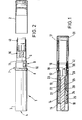
- Figure 1 is a longitudinal section through a stick make-up device according to the present invention;
- Figure 2 is a side view, part cut-away, of the device illustrated in Figure 1, shown with the cap removed, and a stick holding element in its advanced position;
- Figure 3 illustrates, to an enlarged scale, a cap seal of the device of Figures 1 and 2;
- Figure 4 illustrates in perspective, the mutual arrangement of certain components in the assembled device; and
- Figure 5 illustrates to an enlarged scale the cross-sectional configuration of a cup portion of the stick holder element.
- With reference first to Figures 1 and 2, the cosmetics stick device comprises a base part 1, and a
cap 2 which can be removably attached the base part. The base part includes a cylindrical base tube 3 which is closed at its lower end 4 and open at its opposite end. Accommodated partly within this base tube 4 is a cylindricalinner tube 5 which is open at both ends. This inner tube extends inwardly of the base tube from its open end to a position about half way along the length of the base tube, and has a substantial portion 6 which projects outwardly of the base tube. The inner tube is rotatable relative to the base tube. - A generally
tubular retainer ferrule 7 is rigidly fixed to the base tube and includes various portions performing different functions. A part of the ferrule projects outwardly from the open end of the base tube 1 and comprises anannular stop 8 which abuts against the end of the base tube to define the required axial positioning of the ferrule relative to the base tube, and a generally cylindricalcap retaining portion 9 formed with a plurality of circumferentially spacedengagement bumps 10 to engage the inner surface of the cap so as to retain the cap in its closed position. - These
bumps 10 .can be formed by simply outwardly deforming the wall of thecylindrical portion 9 slightly at an appropriate number of circumferentially spaced positions. Theouter end 11 of the ferrule is of slightly reduced diameter to define an opening through which theinner tube 5 projects. - The part of the
ferrule 7 within the base tube 4 includes a reduceddiameter portion 12 adjacent to theannular stop 8, and from thisportion 12, the ferrule widens to an elongatecylindrical engagement portion 13 which is a tight-fit within the base tube so as to retain the ferrule fixed thereto. From thisportion 13, the ferrule narrows slightly to acylindrical base portion 14 the inner end of which is turned inwardly to form a radially inwardly projectingflange 15. Thisinner portion 14 accommodates and fixes one element of a screw advance mechanism to be described below. - The
cap 2 comprises a cylinder of the same outer diameter as that of theouter tube 5 of the base portion, and is closed at its outer end. - The external appearance of the above-described components forming the base portion 1 and the
cap 2 is illustrated in Figure 2. These components may be made of any suitable rigid plastics or metallic material. - Disposed coaxially within the inner tube there is a cosmetics
stick holding element 16 which is arranged to be driven axially so as to cause acosmetics stick 17 shown in dashed lines in Figure 1 to be projected from and retracted within theinner tube 5. Thisstick holding element 16 comprises a generallycylindrical cup portion 18 for holding the cylindrical base portion of thecosmetics stick 17 and a rearwardly extendingscrew shaft 19 which extends axially within the base part 1. As can be seen from Figure 4, this screw shaft is generally of flat configuration having two opposite elongateflat surfaces 20 and two opposite part-cylindrical surfaces 21 formed with flight portions defining a screw thread. - Fixed within the inner end of the
inner tube 5 is acylindrical guide member 22 having at its forward end a wall defining aguide slot 23 through which theshaft 19 may freely move in an axial direction. However, because theshaft 19 cannot rotate in theslot 23, thestick holding element 16 is restrained from rotating relative to theguide 22 and thereby also relative to theinner tube 5. - A
screw driving member 24 comprises aforward driving portion 25 and arear fixing portion 26. Theforward driving portion 25 is disposed within theguide tube 22 and is located axially by engagement of an inwardly projectingannular rib 27 on the inner surface of theguide member 22 in a complimentaryannular groove 28 formed at the rear end of thedrive portion 25. The fit between theguide 22 and thedrive portion 25 of thedriving member 24 is such as to permit relative rotation between these parts, with therib 27 rotationally sliding in thegroove 28. Thedrive portion 25 is formed internally with a helical screw thread which meshes with the screw thread on thescrew shaft 19. - The
retaining portion 26 of thedriving member 24 is firmly fixed in thecylindrical base portion 14 of theretainer ferrule 7. - The components forming the screw advance mechanism, namely the stick-
holding element 16,guide member 22 anddriving member 24, are preferably made of a suitable plastics material such as polyacetal or high density polyethylene providing a smooth screw-advance operation. It will be understood that with the above-described arrangement of components relative rotation between theinner tube 5 and the base tube 3 causes thecup 18 to be driven axially within the inner tube. More particularly, let us assume that theinner tube 5 is held rotationally fixed and the outer tube 3 is rotated. Theretainer ferrule 7 and thedrive member 24 are therefore also rotated, while theguide member 22 is held fixed. The screw threaded engagement between the drivingmember 24 and the screw shaft 19 (which is held rotationally fixed by the guide slot 23) causes rotation of the drivingmember 34 to be converted to axial movement of thestick holding element 16. Rotation of the base tube 3 in one sense drives thecup 8 outwardly from the position shown in Figure 1 to the position shown in Figure 2, while rotation in the opposite sense causes the cup to be retracted. - The inner cylindrical surface of the
cup 18 is preferably formed with a set of circumferentially spaced axially extending and inwardly projectingribs 29 and a ring of circumferentially spaced and extendingribs 30. Theseribs stick 17 and serve to hold thestick 17 firmly in thecup 18. - In accordance with the invention, the device is provided with sealing means to inhibit the egress of vapour formed by evaporation of a volatile binder material used as a constituent in the making of the
stick 17. In the disclosed embodiment, there are two such sealing means, the first comprising a sealingcap 31 fixedly disposed in the end of thecap 2. This sealing cap is shown in greater detail in Figure 3. As can be seen from this Figure, thecap 31 is generally cylindrical and closed at its upper end except for asmall exhaust aperture 32 which is necessary to permit full insertion into theouter cap 2. The sealing cap is made of a suitable flexible plastics material, e.g. low-density polyethylene, and is formed on its outer surface with circumferentially spaced and axially extendinggrooves 33 which allow sufficient deformation of the material of thecap 31 to allow it to be pushed into thecap 2. The generally cylindrical wall of thecap 31 includes anend portion 34 which tapers to a very small thickness at theedge 35. This tapered portion facilitates smooth entry of the outer end of theinner tube 5 into the sealingcap 21 when thecap 2 is placed on the base part 1. - Between the closed end of the cap and this tapered
portion 34 there is acylindrical portion 36 the inner surface of which is formed with anannular sealing bead 37 which may be of triangular, or any other appropriate cross-section. Closer to the closed end of the cap, there is a further, muchwider sealing bead 38. The inner end 39 of the inside frusto-conical surface 40 of the taperingportion 34 forms yet another sealing bead. The inner diameter of thesebeads outer tube 5 so that when the cap is pushed onto the base portion, the end of theinner tube 5 enters thecap 31 through the taperedportion 34 and successively engages and compresses these sealingbeads cap 31 seals over the end of theinner tube 5 and inhibits egress of vapour therefrom. - The other means provided in this embodiment for inhibiting vapour egress and thereby minimising loss of binder from the cosmetics stick, provides a seal between the
cup 18 of the stick holding member and theinner tube 5 in which such member axially moves. This seal is provided by an outwardly extendingcircumferential bead 41 formed on the outer cylindrical surface of thecup 18. This bead is formed so as to have an outer diameter which prior to assembly is very slightly larger than the inner diameter of theinner tube 5. Accordingly, when the cup is inserted into the inner tube during assembly of the device, thisbead 41 becomes slightly compressed so as to form an efficient seal with thetube 5. In the closed position of the device illustrated in Figure 1 with the cosmetics stick 17 fully retracted into theinner tube 5, this sealingbead 41 inhibits the passage of vapour which would otherwise occur through the narrow cylindrical space defined between the outer surface of the cup and the inner surface of theinner tube 5 into the space accommodated by thescrew advance elements inner tube 5 and the inner surface of theretainer ferrule 7 into the annular space between the inner tube and thecap 2. From this space, the vapour could pass to the exterior through the gaps between the cylindricalcap retaining portion 9 of theferrule 7 and the cap itself, these gaps being circumferentially spaced between the cap retaining bumps 10. Figure 5 illustrates the cross-section of thecap 18 to an enlarged scale, and shows that in this embodiment the sealingbead 41 is of generally rectangular cross-section. This figure also shows in greater detail theribs - Thus, it will be understood that the two sealing means comprising the sealing
cap 31 and thebead 41 on thecup 18 serve to define in the closed position of Figure 1, a substantially sealed space which is little greater in volume than the space actually occupied by the cosmetics stick 17. Accordingly, only a small amount of evaporation of the binder material from the cosmetics stick 17 will occur, and the vapour so produced is substantially inhibited from escaping from this space, so in turn inhibiting further evaporation. - Although we have described above a particular construction of a cosmetics stick device utilising the advantageous features of the present invention, it will be appreciated that modifications of the described construction will be apparent to those skilled in the art without departing from the scope of the invention.
- The present invention also embraces any other novel aspects of the device.
Claims (11)
1. A holder assembly for a stick of consumable material including a volatile constituent material, the assembly comprising:
a base for holding the stick; and
a cap removably engageable with the base to close the assembly; characterised by
sealing means (31;41) arranged to inhibit the egress from the closed assembly of vapour formed therein by evaporation of said volatile material from the material stick.
2. A holder assembly for a stick of solid consumable material including a volatile constituent material, the assembly comprising:
a base adapted to hold the stick; and
a cap which is removably engageable with the base to close the assembly; characterised by
sealing means (31) which is arranged to provide a seal between the cap (2) and the base (1) so as to inhibit the egress from the closed assembly of vapour formed therein by evaporation of said volatile material from the material stick.
3. A holder assembly according to claim 2 wherein the base includes a tubular component (5) and the sealing means (31) comprises an insert member made from a resiliently deformable material, said insert member being fixed inside the cap so as to sealingly engage the outer surface of said tubular component.
4. A holder assembly according to claim 3 wherein the base further includes means (19, 22, 24) for causing the material stick to be selectively projected from or retracted within said tubular component and wherein said insert member is a cap-shaped member located inside the cap at the closed end thereof and shaped so as to fit over and seal against that end of said tubular component from which the material stick can project.
5. A holder assembly according to claim 4 wherein said cap-shaped member has a cylindrical body portion, (36) the inside cylindrical surface of which is formed with one or more annular inwardly projecting sealing beads (37, 38, 39) dimensioned to form a tight-fit on the outer cylindrical surface of said tubular component of the base.
6. A holder assembly according to claim 4 or claim 5 wherein said base comprises an outer tube (3) closed at one end, an inner tube, constituting said tubular component, disposed coaxially in the outer tube with a portion projecting axially from the open end of the outer tube, and a stick holder member (18) axially movable within the inner tube;
said two tubes being relatively rotatable to drive said stick holder member axially within the inner tube to advance and retract the material stick.
said two tubes being relatively rotatable to drive said stick holder member axially within the inner tube to advance and retract the material stick.
7. A holder assembly according to claim 6 wherein the arrangement is such that in the retracted position, the stick is accommodated wholly within the inner tube.
8. A holder assembly for a stick of a solid consumable material including a volatile constituent material, the assembly comprising:
characterised in that there is provided sealing means (41) providing a seal between said carrying element and said base member so as to inhibit egress of vapour formed by evaporation of said volatile material from the material stick into a space within the base member form which it could escape through a gap or gaps between said first and second parts.
an elongate hollow base member which is open at one end and which comprises first and second relatively movable parts;
a cap adapted to fit over said open end of said base member to close the assembly;
an element disposed within said base member for carrying a said stick; and
a mechanism responsive to relative movement of said first and second parts of said base member for driving said carrying element axially within said base member between a first position in which the stick projects from said open end, and a second position in which the stick is at least partly retracted within said base member;
characterised in that there is provided sealing means (41) providing a seal between said carrying element and said base member so as to inhibit egress of vapour formed by evaporation of said volatile material from the material stick into a space within the base member form which it could escape through a gap or gaps between said first and second parts.
9. A holder assembly according to claim 8 wherein said first and second parts of said base comprise an outer tube (3) closed at one end and an inner tube (5) disposed coaxially and rotatably within the outer tube, the stick carrying element (18) being arranged to move axially within the inner tube.
10. A holder assembly according to claim 9 wherein said stick carrying element is in the form of a cylindrical cup for fixedly accommodating a base portion of the stick, said cup being formed with an annular outwardly projecting resiliently deformable bead (41) constituting the sealing means, said bead engaging against the inner cylindrical surface of the inner tube.
11. A holder assembly for a stick of a solid consumable material including a volatile constituent material, the assembly comprising:
characterised in that there is provided first sealing means (31) arranged to provide a seal between the cap and the base so as to inhibit the egress from the closed assembly of vapour formed therein by evaporation of said volatile material from the material stick, and second sealing means (41) providing a seal between said carrying element and said base member so as to inhibit egress of vapour formed by evaporation of said volatile material from the material stick into a space within the base member from which it could escape through a gap or gaps between said first and second parts.
an elongate hollow base member which is open at one end and which comprises first and second relatively movable parts;
a cap adapted to fit over said open end of said base member to close the assembly;
an element disposed within said base member for carrying a said stick; and
a mechanism responsive to relative movement of said first and second parts of said base member for driving said carrying element axially within said base member between a first position in which the stick projects from said open end, and a second position in which the stick is at least partly retracted within said base member;
characterised in that there is provided first sealing means (31) arranged to provide a seal between the cap and the base so as to inhibit the egress from the closed assembly of vapour formed therein by evaporation of said volatile material from the material stick, and second sealing means (41) providing a seal between said carrying element and said base member so as to inhibit egress of vapour formed by evaporation of said volatile material from the material stick into a space within the base member from which it could escape through a gap or gaps between said first and second parts.
Applications Claiming Priority (2)
| Application Number | Priority Date | Filing Date | Title |
|---|---|---|---|
| GB8429176 | 1984-11-19 | ||
| GB848429176A GB8429176D0 (en) | 1984-11-19 | 1984-11-19 | Holder for cosmetics stick |
Publications (2)
| Publication Number | Publication Date |
|---|---|
| EP0182655A2 true EP0182655A2 (en) | 1986-05-28 |
| EP0182655A3 EP0182655A3 (en) | 1986-12-10 |
Family
ID=10569929
Family Applications (1)
| Application Number | Title | Priority Date | Filing Date |
|---|---|---|---|
| EP85308424A Withdrawn EP0182655A3 (en) | 1984-11-19 | 1985-11-19 | Holder for cosmetics stick |
Country Status (2)
| Country | Link |
|---|---|
| EP (1) | EP0182655A3 (en) |
| GB (1) | GB8429176D0 (en) |
Cited By (14)
| Publication number | Priority date | Publication date | Assignee | Title |
|---|---|---|---|---|
| WO1989006097A1 (en) * | 1987-12-31 | 1989-07-13 | Georg Karl Geka-Brush Gmbh | Dosing propelling pencil for dispensing free-flowing materials |
| US4950094A (en) * | 1989-07-26 | 1990-08-21 | The Gillette Company | Cosmetic dispenser and method |
| EP0492266A1 (en) * | 1990-12-28 | 1992-07-01 | KOTOBUKI & CO., LTD. | A twintype stick-shaped material drawing-out container |
| EP0524670A1 (en) * | 1991-06-24 | 1993-01-27 | Unilever N.V. | Lipstick article |
| FR2698249A1 (en) * | 1992-11-24 | 1994-05-27 | Suzuno Kasei Co Ltd | Mechanism for supplying cosmetic products of the stick type, the container employing it and the cartridge used therein. |
| EP0617905A2 (en) * | 1993-03-29 | 1994-10-05 | KOTOBUKI & CO., LTD. | Stick-shaped piece drive container and stick-shaped piece supplying cassette |
| DE19616613C1 (en) * | 1996-04-25 | 1997-10-02 | Kaesmacher Gmbh & Co Kg | Cosmetic stick, used as lipstick, eye pencil etc. |
| US5700101A (en) * | 1987-10-09 | 1997-12-23 | Kotobuki & Co., Ltd. | Writing tool |
| FR2750302A1 (en) * | 1996-06-26 | 1998-01-02 | Oreal | STICK HOLDER FOR A STICK OF LIP PRODUCT AND CASE THUS EQUIPPED |
| WO1999001052A1 (en) * | 1997-07-02 | 1999-01-14 | Henlopen Manufacturing Co., Inc. | Applicator for liquid material |
| FR2771606A3 (en) * | 1997-12-03 | 1999-06-04 | Rexam Reboul | Case for lipstick or similar with cap |
| EP0981976A2 (en) * | 1998-08-27 | 2000-03-01 | Kotobuki Printing Co., Ltd. | Rotary stick projecting device |
| US6116801A (en) * | 1998-07-17 | 2000-09-12 | Revlon Consumer Products Corporation | Product dispenser and holder |
| US7144171B2 (en) | 2000-03-16 | 2006-12-05 | L'oreal | Device for packaging and applying a cosmetic or care product |
Citations (7)
| Publication number | Priority date | Publication date | Assignee | Title |
|---|---|---|---|---|
| US3589821A (en) * | 1968-08-09 | 1971-06-29 | Lever Brothers Ltd | Container-dispenser for cosmetics |
| US3907441A (en) * | 1974-12-30 | 1975-09-23 | Eyelet Specialty Co | Sealed container for dispensing a volatile product |
| US4139311A (en) * | 1976-05-03 | 1979-02-13 | Willy Lorscheidt | Dispensing cartridge having an improved automatic filler stick positioning mechanism |
| DE2807472A1 (en) * | 1978-02-22 | 1979-08-23 | Wischerath Kg Josef | Rotary casing for cosmetic - consists of spindle assembly with turning base, and ventilation and filler openings |
| US4232977A (en) * | 1978-10-18 | 1980-11-11 | The Procter & Gamble Company | Package for antiperspirant/deodorant |
| EP0070257A2 (en) * | 1981-07-10 | 1983-01-19 | Compagnie Française des Matières Plastiques " PLASCO" S.A. | Package for a stick, in particular body-treatment stick, with a tubular body and an adjusting part |
| DE3316573A1 (en) * | 1983-05-06 | 1984-11-08 | Bramlage Gmbh, 2842 Lohne | Casing for lipsticks or the like |
-
1984
- 1984-11-19 GB GB848429176A patent/GB8429176D0/en active Pending
-
1985
- 1985-11-19 EP EP85308424A patent/EP0182655A3/en not_active Withdrawn
Patent Citations (7)
| Publication number | Priority date | Publication date | Assignee | Title |
|---|---|---|---|---|
| US3589821A (en) * | 1968-08-09 | 1971-06-29 | Lever Brothers Ltd | Container-dispenser for cosmetics |
| US3907441A (en) * | 1974-12-30 | 1975-09-23 | Eyelet Specialty Co | Sealed container for dispensing a volatile product |
| US4139311A (en) * | 1976-05-03 | 1979-02-13 | Willy Lorscheidt | Dispensing cartridge having an improved automatic filler stick positioning mechanism |
| DE2807472A1 (en) * | 1978-02-22 | 1979-08-23 | Wischerath Kg Josef | Rotary casing for cosmetic - consists of spindle assembly with turning base, and ventilation and filler openings |
| US4232977A (en) * | 1978-10-18 | 1980-11-11 | The Procter & Gamble Company | Package for antiperspirant/deodorant |
| EP0070257A2 (en) * | 1981-07-10 | 1983-01-19 | Compagnie Française des Matières Plastiques " PLASCO" S.A. | Package for a stick, in particular body-treatment stick, with a tubular body and an adjusting part |
| DE3316573A1 (en) * | 1983-05-06 | 1984-11-08 | Bramlage Gmbh, 2842 Lohne | Casing for lipsticks or the like |
Cited By (19)
| Publication number | Priority date | Publication date | Assignee | Title |
|---|---|---|---|---|
| US5700101A (en) * | 1987-10-09 | 1997-12-23 | Kotobuki & Co., Ltd. | Writing tool |
| WO1989006097A1 (en) * | 1987-12-31 | 1989-07-13 | Georg Karl Geka-Brush Gmbh | Dosing propelling pencil for dispensing free-flowing materials |
| US4950094A (en) * | 1989-07-26 | 1990-08-21 | The Gillette Company | Cosmetic dispenser and method |
| EP0492266A1 (en) * | 1990-12-28 | 1992-07-01 | KOTOBUKI & CO., LTD. | A twintype stick-shaped material drawing-out container |
| EP0524670A1 (en) * | 1991-06-24 | 1993-01-27 | Unilever N.V. | Lipstick article |
| FR2698249A1 (en) * | 1992-11-24 | 1994-05-27 | Suzuno Kasei Co Ltd | Mechanism for supplying cosmetic products of the stick type, the container employing it and the cartridge used therein. |
| EP0617905A3 (en) * | 1993-03-29 | 1995-05-24 | Kotobuki & Co Ltd | Stick-shaped piece drive container and stick-shaped piece supplying cassette. |
| EP0617905A2 (en) * | 1993-03-29 | 1994-10-05 | KOTOBUKI & CO., LTD. | Stick-shaped piece drive container and stick-shaped piece supplying cassette |
| DE19616613C1 (en) * | 1996-04-25 | 1997-10-02 | Kaesmacher Gmbh & Co Kg | Cosmetic stick, used as lipstick, eye pencil etc. |
| US5888004A (en) * | 1996-06-26 | 1999-03-30 | L'oreal | Cup with a grooved interior side wall for holding a cosmetic stick |
| EP0815766A1 (en) * | 1996-06-26 | 1998-01-07 | L'oreal | Stick holder cup for a lip product stick and case with such a device |
| FR2750302A1 (en) * | 1996-06-26 | 1998-01-02 | Oreal | STICK HOLDER FOR A STICK OF LIP PRODUCT AND CASE THUS EQUIPPED |
| WO1999001052A1 (en) * | 1997-07-02 | 1999-01-14 | Henlopen Manufacturing Co., Inc. | Applicator for liquid material |
| US6186686B1 (en) * | 1997-07-02 | 2001-02-13 | Henlopen Manufacturing Co., Inc. | Applicator for liquid material |
| FR2771606A3 (en) * | 1997-12-03 | 1999-06-04 | Rexam Reboul | Case for lipstick or similar with cap |
| US6116801A (en) * | 1998-07-17 | 2000-09-12 | Revlon Consumer Products Corporation | Product dispenser and holder |
| EP0981976A2 (en) * | 1998-08-27 | 2000-03-01 | Kotobuki Printing Co., Ltd. | Rotary stick projecting device |
| EP0981976A3 (en) * | 1998-08-27 | 2002-03-27 | Kotobuki Printing Co., Ltd. | Rotary stick projecting device |
| US7144171B2 (en) | 2000-03-16 | 2006-12-05 | L'oreal | Device for packaging and applying a cosmetic or care product |
Also Published As
| Publication number | Publication date |
|---|---|
| EP0182655A3 (en) | 1986-12-10 |
| GB8429176D0 (en) | 1984-12-27 |
Similar Documents
| Publication | Publication Date | Title |
|---|---|---|
| EP0182655A2 (en) | Holder for cosmetics stick | |
| CA2421987C (en) | Cosmetic container with interchangeable attachments | |
| US4363560A (en) | Propel-repel solid stick dispenser | |
| US5833382A (en) | Push-up dispenser suitable for dilatant materials | |
| US6371129B1 (en) | Dispenser for fluid materials | |
| AU701076B2 (en) | A container for storing and dispensing a dental substance | |
| US7168435B2 (en) | Material dispenser with applicator | |
| US5255990A (en) | Reset elevator/threaded shaft dispensing package for stick form product and a refill cartridge therefor | |
| US4580920A (en) | Stick dispenser | |
| JPH0356165A (en) | Distributor | |
| US6174099B1 (en) | Device for applying liquid cosmetic products | |
| US5997201A (en) | Holder for a stick of a spreadable substance | |
| US10874193B2 (en) | Wheel actuated cosmetic stick | |
| EP0178188A2 (en) | Stick holder device | |
| JP3202178B2 (en) | Cosmetic application container | |
| US2840231A (en) | Moisture proof propellent applicator | |
| JP2786592B2 (en) | Cartridge type cosmetic pressurized container | |
| JP3527293B2 (en) | Stick-shaped cosmetic feeding container | |
| JP2000350617A (en) | Cosmetics vessel | |
| US5893672A (en) | Viscid substance recovery and dispenser device | |
| EP0209361A2 (en) | Material applicator | |
| JPS6138488Y2 (en) | ||
| JP2540480Y2 (en) | Liquid cosmetic container | |
| GB2252940A (en) | Pencil for cosmetic use or for drawing with sharpener | |
| JP4559559B2 (en) | Cosmetic container |
Legal Events
| Date | Code | Title | Description |
|---|---|---|---|
| PUAI | Public reference made under article 153(3) epc to a published international application that has entered the european phase |
Free format text: ORIGINAL CODE: 0009012 |
|
| AK | Designated contracting states |
Kind code of ref document: A2 Designated state(s): DE FR GB |
|
| PUAL | Search report despatched |
Free format text: ORIGINAL CODE: 0009013 |
|
| AK | Designated contracting states |
Kind code of ref document: A3 Designated state(s): DE FR GB |
|
| STAA | Information on the status of an ep patent application or granted ep patent |
Free format text: STATUS: THE APPLICATION IS DEEMED TO BE WITHDRAWN |
|
| 18D | Application deemed to be withdrawn |
Effective date: 19870611 |
|
| RIN1 | Information on inventor provided before grant (corrected) |
Inventor name: HURRELL, EDWARD TREVOR |