EP0182586A2 - Ensemble de mandrins extensibles - Google Patents
Ensemble de mandrins extensibles Download PDFInfo
- Publication number
- EP0182586A2 EP0182586A2 EP85308226A EP85308226A EP0182586A2 EP 0182586 A2 EP0182586 A2 EP 0182586A2 EP 85308226 A EP85308226 A EP 85308226A EP 85308226 A EP85308226 A EP 85308226A EP 0182586 A2 EP0182586 A2 EP 0182586A2
- Authority
- EP
- European Patent Office
- Prior art keywords
- mandrel
- clamping
- air
- tooling bar
- collet
- Prior art date
- Legal status (The legal status is an assumption and is not a legal conclusion. Google has not performed a legal analysis and makes no representation as to the accuracy of the status listed.)
- Granted
Links
Images


Classifications
-
- B—PERFORMING OPERATIONS; TRANSPORTING
- B23—MACHINE TOOLS; METAL-WORKING NOT OTHERWISE PROVIDED FOR
- B23B—TURNING; BORING
- B23B29/00—Holders for non-rotary cutting tools; Boring bars or boring heads; Accessories for tool holders
- B23B29/02—Boring bars
-
- B—PERFORMING OPERATIONS; TRANSPORTING
- B23—MACHINE TOOLS; METAL-WORKING NOT OTHERWISE PROVIDED FOR
- B23Q—DETAILS, COMPONENTS, OR ACCESSORIES FOR MACHINE TOOLS, e.g. ARRANGEMENTS FOR COPYING OR CONTROLLING; MACHINE TOOLS IN GENERAL CHARACTERISED BY THE CONSTRUCTION OF PARTICULAR DETAILS OR COMPONENTS; COMBINATIONS OR ASSOCIATIONS OF METAL-WORKING MACHINES, NOT DIRECTED TO A PARTICULAR RESULT
- B23Q2220/00—Machine tool components
- B23Q2220/008—Rotatable tool holders coupled in parallel to a non rotating accessory
-
- Y—GENERAL TAGGING OF NEW TECHNOLOGICAL DEVELOPMENTS; GENERAL TAGGING OF CROSS-SECTIONAL TECHNOLOGIES SPANNING OVER SEVERAL SECTIONS OF THE IPC; TECHNICAL SUBJECTS COVERED BY FORMER USPC CROSS-REFERENCE ART COLLECTIONS [XRACs] AND DIGESTS
- Y10—TECHNICAL SUBJECTS COVERED BY FORMER USPC
- Y10S—TECHNICAL SUBJECTS COVERED BY FORMER USPC CROSS-REFERENCE ART COLLECTIONS [XRACs] AND DIGESTS
- Y10S408/00—Cutting by use of rotating axially moving tool
- Y10S408/708—Drilling opening for bearing in engine block
-
- Y—GENERAL TAGGING OF NEW TECHNOLOGICAL DEVELOPMENTS; GENERAL TAGGING OF CROSS-SECTIONAL TECHNOLOGIES SPANNING OVER SEVERAL SECTIONS OF THE IPC; TECHNICAL SUBJECTS COVERED BY FORMER USPC CROSS-REFERENCE ART COLLECTIONS [XRACs] AND DIGESTS
- Y10—TECHNICAL SUBJECTS COVERED BY FORMER USPC
- Y10T—TECHNICAL SUBJECTS COVERED BY FORMER US CLASSIFICATION
- Y10T279/00—Chucks or sockets
- Y10T279/10—Expanding
- Y10T279/1004—Collet type
- Y10T279/1008—Fixed jaws and moving cam
-
- Y—GENERAL TAGGING OF NEW TECHNOLOGICAL DEVELOPMENTS; GENERAL TAGGING OF CROSS-SECTIONAL TECHNOLOGIES SPANNING OVER SEVERAL SECTIONS OF THE IPC; TECHNICAL SUBJECTS COVERED BY FORMER USPC CROSS-REFERENCE ART COLLECTIONS [XRACs] AND DIGESTS
- Y10—TECHNICAL SUBJECTS COVERED BY FORMER USPC
- Y10T—TECHNICAL SUBJECTS COVERED BY FORMER US CLASSIFICATION
- Y10T279/00—Chucks or sockets
- Y10T279/10—Expanding
- Y10T279/1021—Fluid-pressure actuator
- Y10T279/1033—Expanding jaws via mechanical connection
-
- Y—GENERAL TAGGING OF NEW TECHNOLOGICAL DEVELOPMENTS; GENERAL TAGGING OF CROSS-SECTIONAL TECHNOLOGIES SPANNING OVER SEVERAL SECTIONS OF THE IPC; TECHNICAL SUBJECTS COVERED BY FORMER USPC CROSS-REFERENCE ART COLLECTIONS [XRACs] AND DIGESTS
- Y10—TECHNICAL SUBJECTS COVERED BY FORMER USPC
- Y10T—TECHNICAL SUBJECTS COVERED BY FORMER US CLASSIFICATION
- Y10T279/00—Chucks or sockets
- Y10T279/10—Expanding
- Y10T279/1037—Axially moving actuator
- Y10T279/1041—Wedge
-
- Y—GENERAL TAGGING OF NEW TECHNOLOGICAL DEVELOPMENTS; GENERAL TAGGING OF CROSS-SECTIONAL TECHNOLOGIES SPANNING OVER SEVERAL SECTIONS OF THE IPC; TECHNICAL SUBJECTS COVERED BY FORMER USPC CROSS-REFERENCE ART COLLECTIONS [XRACs] AND DIGESTS
- Y10—TECHNICAL SUBJECTS COVERED BY FORMER USPC
- Y10T—TECHNICAL SUBJECTS COVERED BY FORMER US CLASSIFICATION
- Y10T408/00—Cutting by use of rotating axially moving tool
- Y10T408/39—Cutting by use of rotating axially moving tool with radially outer limit of cutting edge moving to define cylinder partially, but not entirely encircled by work
-
- Y—GENERAL TAGGING OF NEW TECHNOLOGICAL DEVELOPMENTS; GENERAL TAGGING OF CROSS-SECTIONAL TECHNOLOGIES SPANNING OVER SEVERAL SECTIONS OF THE IPC; TECHNICAL SUBJECTS COVERED BY FORMER USPC CROSS-REFERENCE ART COLLECTIONS [XRACs] AND DIGESTS
- Y10—TECHNICAL SUBJECTS COVERED BY FORMER USPC
- Y10T—TECHNICAL SUBJECTS COVERED BY FORMER US CLASSIFICATION
- Y10T408/00—Cutting by use of rotating axially moving tool
- Y10T408/55—Cutting by use of rotating axially moving tool with work-engaging structure other than Tool or tool-support
- Y10T408/557—Frictionally engaging sides of opening in work
- Y10T408/558—Opening coaxial with Tool
Definitions
- THIS INVENTION relates to a mandrel assembly, and in particular to apparatus for and a method of clamping on the inner surface of a clampinq aperture to journal a rotatable tooling bar.
- U.S. Patents Nos. 2,020,439 and 3,674,375 disclose the concept of guiding a boring bar at two axially separated places, with the boring tool between.
- These patents, as well as U.S. Patents Nos. 2,065,486 and 3,977,805 also disclose the concept of utilizing a type of universal joint so that the axis of the boring tool and the axis of the drive therefor need not be in exact alignment.
- U.S. Patent No. 4,365,917 discloses an arrangement which permits angular adjustment and clamping of a spherical guide bushing by means of air pressure.
- annular surfaces on the two spaced portions of the workpiece were machined, each normal to the adjacent aperture axis, and hence it was presumed that these two annular machined surfaces were parallel. In a large valve body which might be four or five feet (1.2m or 1.5m) long, this machining could take days to complete.
- a problem to be solved is how to precision machine an annular surface on a workpiece, which surface is normal to the axis of an aperture in the workpiece, and to accomplish this quickly enough to lower the cost of manufacture radicall.y.
- Another problem is how to machine two axially spaced annular surfaces on a workpiece, with each annular surface adjacent axially spaced apertures in the workpiece, and to have these two annular surfaces lie in parallel planes.
- apparatus for clamping on the inner surface of a clamping aperture to journal a rotatable tooling bar
- the apparatus comprising: a mandrel carrying an expansible collet such that an annular journal surface rotatable with the tooling bar is arranged to cooperate with a bearing surface on a body of the mandrel; an air pressure expansible chamber in the mandrel; force transfer means betweeen the expansible chamber and the expansible collet; means for supplying air under pressure to a space between the journal and bearing surfaces to establish an air bearing of a tooling bar in the mandrel; and means for supplying air under pressure into the expansible chamber to expand the collet against the inner surface of the clamping aperture to clamp the mandrel within the clamping aperture.
- the present invention provides a method of clamping a mandrel assembly into a clamping aperture to journal a rotatable tooling bar adapted to have a cutting tool rotatable therewith, the mandrel assembly including a mandrel carrying an expansible collet with a journal surface rotatable with the tooling bar closely cooperable with a bearing surface on a body of the mandrel, an air pressure expansible chamber in the mandrel body, and force transfer means between the expansible chamber and the expansible collet, the method comprising supplying air under pressure to a space between the journal and bearing surfaces to establish an air bearing centering the mandrel around the tooling bar: and supplying air under pressure into the expansible chamber to expand the expanding collet against an inner surface of the clamping aperture to clamp the mandrel within the clamping aperture.
- apparatus for clamping on the inner surface of a clamping aperture to journal a rotatable tooling bar
- a mandrel in said mandrel assembly and having a body, an air pressure expansible chamber in said mandrel body, an expanding collet carried on said mandrel body, force transfer means connected between said expansible chamber and said collet, an annular journal surface rotatable with said tooling bar, an annular bearinq surface on said mandrel body in close proximity to said annular journal surface, and means connected to said mandrel body adapted to supply air under pressure to the annular space between said annular journal and bearing surfaces to establish an air bearing of said tooling bar in said mandrel body, and to supply air into said expansible chamber to expand said expanding
- a second mandrel adapted to be clamped in an axially spaced second aperture is provided to journal a second axially aligned journal surface so as to be rotatable with the tooling bar.
- a universal joint is provided at one end of the tooling bar; and means are provided to rotate the tooling bar via the universal joint.
- an inner sleeve is included in the mandrel body, the annular bearing surface, which is preferably a cylindrical surface, being on the inner sleeve.
- the air pressure expansible chamber includes a relatively axially movable piston and cylinder means and generally the force transfer means includes cam means so that, in a preferred arrangement, the expansible chamber has axial movement transformed by the cam means into radial movement of the expansible collet.
- the air supply means is external to said tooling bar and usually the air supply means includes an internal aperture in the tooling bar.
- the apparatus includes an enlarged portion on the tooling bar, a transverse aperture through the enlarged portion, and a cutter assembly receivable in the transverse aperture and having a radial dimension larger than the clamping aperture to machine a surface on a workpiece.
- apparatus for clamping on the inner surface of a clamping aperture to journal a rotatable tooling bar adapted to have a cutting tool rotatable therewith, the mandrel assembly including a mandrel having an expansible collet on a mandrel body with an annular journal surface rotatable with the tooling bar closely cooperable with an annular bearing surface on the mandrel body, which apparatus further comprises an air pressure expansible chamber in said mandrel body, force transfer means between said expansible chamber and said expansible collet, means for supplying air under pressure to the annular space between said annular journal and bearing surfaces to establish an air bearing of the tooling bar in said mandrel, and means for supplying air under pressure into said expansible chamber to expand the expanding collet against the inner surface of the clamping aperture to clamp the mandrel within the clamping aperture.
- the apparatus includes a second mandrel adapted to be clamped in an axially spaced second clamping aperture, and means journalling a second axially spaced annular journal surface to be rotatable with the tooling bar in the second mandrel.
- the expansible chamber is piston means within cylinder means.
- the expansible chamber has axial movement and the force transfer means transforms the axial movement into substantially radial movement of the expansible collet.
- the force transfer means includes force multiplying means.
- the air bearing is a radial bearing
- the means for supplying air under pressure is arranged to centre the mandrel assembly around the tooling bar.
- the present invention provides a method of clamping a mandrel assembly into a clamping aperture to journal a rotatable tooling bar adapted to have a cutting tool rotatable therewith, the mandrel assembly including a mandrel having an expansible collet on a mandrel body with an annular journal surface rotatable with the tooling bar closely cooperable with an annular bearing surface on the mandrel body, said method comprising the steps of providing an air pressure expansible chamber in the mandrel body, providing force transfer means between the expansible chamber and the expansible collet, supplying air under pressure to the annular space between the annular journal and bearing surfaces to establish an air bearing centering the mandrel around the tooling bar, and supplying air under pressure into said expansible chamber to expand the expanding collet against the inner surface of the clamping aperture to clamp the mandrel within the clamping aperture.
- the expansible chamber is supplied with air beld from the air bearing and/or the expansible chamber.
- the method includes journalling a second axially spaced annular journal surface to be rotatable with the tooling bar in a second mandrel adapted to be clamped in an axially spaced second clamping aperture.
- each collet has a convex shape for self-aligned clamping of the two mandrels in the clamping apertures.
- air is continued to be supplied under pressure to the annular space between the annular journal and bearing surfaces during rotation of the tooling bar and machining with the rotatable cutting tool is carried out to establish an air bearing support and centering of the tooling bar within the or each mandrel.
- apparatus and a method embodying the present invention enable the provision of a precision machining apparatus and method in which a mandrel is first centered around a tooling bar and then clamped in position in a clamping aperture, which provides a dual use of air pressure for actuating an expanding mandrel and which also provides an air bearing of a rotatable tooling bar.
- Apparatus and a method embodying the invention also allows a triple use of air pressure, to center a mandrel around a tooling bar, to expand a collet in the mandrel to clamp in a clamping aperture, and to provide an air bearing support of a rotating tooling bar during machining.
- Figures 2 to 5 show a mandrel assembly I embodying the invention, which includes generally first and second mandrel bodies 12 and 13, respectively, and a tooling bar 14.
- the mandrel assembly I I is adapted to be clamped on the inner surface of first and second clamping apertures 15 and 16, respectively.
- These clamping apertures may be part of the machine tool, or a fixture, but in this embodiment are a part of a long workpiece 17 which additionally has a third aperture 18 through which the tooling bar 14 extends.
- the workpiece 17 is an example of a workpiece which is difficult to machine with accuracy because of its length, which might be four or five feet (1.2m or 1.5m), and because of limited access through a transverse aperture 19.
- the apertures 15, 16, and 18 have previously been bored by a boring tool on a long boring bar. Because of the considerable length-to-diameter ratio of that long, slender boring bar, the three apertures 15, 16, and 18 have often been found to be not exactly coaxial. In other words, the boring bar may bend slightly during machining of these three apertures 15, 16, and 18. Alternatively, if bored from opposite ends, the three apertures could be misaligned.
- the prior art practice was to ream these bored holes to a more precise diameter; however, the reamer also was necessarily long relative to its diameter, and hence slightly flexible, so that generally if the apertures were not coaxial when bored, they were still not coaxial after reaming.
- An example of a difficult-to-machine workpiece is a large valve body which might have multiple gate valves along it, such as would extend transversely through the transverse aperture 19.
- An annular surface 21 on the workpiece 17 adjacent the aperture 15 and an annular surface 22 adjacent the aperture 16 were desired to be machined by the mandrel assembly 11. These two annular surfaces would eventually accept valve seats parallel to_these annular surfaces 21 and 22, and then a gate valve would be movable through the transverse aperture 19 perpendicular to the axis of the surfaces 21 and 22 in order to close or open this gate valve.
- the gate valve would not leak fluid, which fluid eventually would be passing through the apertures 15, 16, and 18, it was imperative that the valve seats be precisely positioned, which meant that the two machined annular surfaces 21 and 22 should be parallel.
- FIG. 1 a portion of the workpiece 17 is illustrated, to an enlarged scale relative to that shown in FIG. 2.
- This workpiece in FIG. 1 shows the clamping apertures 15 and 16 which have been previously bored, and this figure illustrates, to a slightly exaggerated scale, that these two apertures are not coaxial because of the bending of the elongated boring bar which had previously bored these apertures.
- Guide bushings 26 and 27 were machined to have a close fit inside the apertures 15 and 16.
- a tooling bar 28 was guided by these guide bushings 26 and 27 and had wear strips 29, usually four in number, mounted in keyway-type slots in the tooling bar 28.
- the guide bushings and the wear strips could all be made from bronze, for example, and the wear strips could be replaced as they wore.
- a tool 31 rotated by the tooling bar 28 could be used to machine the annular surface 21A, and a tool 32, also rotated by the tooling bar 28, could be used to machine the annular surface 22A. In the latter case, this would'be with the tooling bar 28 longitudinally moved to engage that portion of the workpiece 17 adjacent the aperture 16.
- the wear strips were machined to have a close fit inside the guide bushings 26 and 27; hence, this meant that the tooling bar 28 would be bowed in the direction of the arrow 33 because the two apertures 15 and 16 were not coaxial. Also, this meant that there would be excessive wear on the guide bushings 15 at points 34 and 35, and also excessive wear on the wear strips 29 at corresponding locations; and that, similarly, there would be excessive wear on the guide bushing 27 at points 36 and 37 and wear on the wear strips 29 adjacent guide bushing 27 at corresponding locations. Even though the apertures 15 and 16 had been bored and then subsequently reamed to try to make them coaxial, it was found that in many cases they were not coaxial; hence, the machined surfaces 21A and 22A were not parallel with each other.
- valve seats were mounted in these machined annular surfaces 21A and 22A and a gate valve moved in the transverse aperture 19, to and fro along the direction of the arrow 33, it did not have a good sealing engagement with the valve seats, and would leak. Also, as the wear strips and guide bushings would wear, the tooling bar 28 would chatter in these guide bushings to provide a distorted machined annular surface 21A and 22A.
- the tooling bar 14 may be) many different forms of bars capable of performing machining, including drills, reamers, and milling cutters, and has been shown as a boring bar carrying two diametrically opposed cutting tools 40 to machine the annular surface 21. Such tools can make a cut for the annular surface 21 by the axial and rotational movement of the tooling bar 14.
- the tooling bar 14 may be driven by a machine spindle (not shown) having a drive end 41 connected through a universal joint 42 to a drive shaft 43, which may be connected by a conical driver 44 to a drive spindle (not shown).
- the purpose of the universal joint 42 is to provide rotation of the tooling bar 14 despite slight misalignments of the apertures 15, 16, and 18, so as to not place any lateral thrust or bending moment on such tooling bar 14.
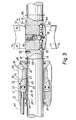
- the two mandrels 12 and 13 may be identical, although reversed end-for-end in position, and hence only the mandrel 12 will be described in detail with reference to FIG. 3.
- the mandrel 12 includes an annular mandrel body 48 which is threaded at 49 to receive a bearing sleeve 50, which may be bronze, for example.
- 0-rings 53 establish an axially sliding seal of the piston within the cylinder.
- An annular expandable collet 54 surrounds and is carried by the mandrel body 48, the bearing sleeve 50, and the piston 52.
- Force transfer means 55 is connected between the piston 52 and the expandable collet. This force transfer means transfers the axial movement of the piston 52 into generally a radial movement of the collet 54.
- This force transfer means 55 includes cam surfaces 56 on the piston 52 and on the bearing sleeve 50, and includes cam follower surfaces 57 on the inner periphery of the collet 54.
- Means is provided to supply air pressure to said annular cylinder 51 and this includes an air supply conduit 60 soldered or otherwise secured in the mandrel body 48 and having a quick-disconnect coupling 61, as shown in FIG. 2.
- Radial apertures 62 preferably three in number and equally spaced, lead from the annular cylinder 51 to a small reservoir 63 formed by a relieved portion in the bearing sleeve 50.
- An annular journal surface 65 is rotatable with the tooling bar 14 and in this preferred embodiment is a part of the surface of this tooling bar.
- This annular journal surface is in close proximity to an annular bearing surface 66 on the mandrel 12. In this preferred embodiment, the bearing surface 66 is all on the inner surface of the bearing sleeve 50.
- the axial lengths of the bearing surfaces 66 at each end of the mandrel 12 are approximately equal, at each end of the reservoir 63, in order to establish equal radial forces as an air bearing by air pressure leading from the cylinder 51 and from the reservoir 63.
- the annular bearing and Journal urfaces have a smooth finish, in the order of microinch (0.76 mm-1mm) surface finish, and the radial clearance is in the order of 0.0005 inch (0.013mm) (51mm) such conditions, a 2-inch diameter tooling bar and with bearing surfaces 66 which are 1- 1/4 (32mm) inche long, the air bearing is capable of supporting 600-700 pounds (272Kg to 318Kg) of lateral force.
- C-clips 67 fit in grooves 68 in the tooling bar 14 to retain the mandrel 12 on the tooling bar 14, and wiper seals 69 keep dirt and other contaminants out of the air bearing.
- a cutter assembly 71 is mountable on the tooling bar 14.
- This cutter assembly includes a cutter body 72 which is closely received within a transverse aperture 73 in an enlarged portion 74 of the tooling bar 14.
- This cutter body 72 mounts cutting tools, such as cutting inserts 75 and 76, for concurrent machining of the annular surface 21 at two diametrically opposed locations.
- the cutting body may mount a cutting insert 77 for only single-point cutting of the annular surface 21, and may also mount a cutting insert 78 for single-point cutting of the second annular surface 22, when the tooling bar 14 is fed to the right, as viewed in FIGS. 2-5.
- the cutting body 72 may be mounted in the transverse aperture in any suitable manner, and in the preferred embodiment, a screw 80 acts through a central ball 81 and a plurality of radially arranged balls 82 to lock behind a chamfered shoulder 83 on the enlarged portion 74.
- the cutter body 72 has a flange 84 to engage the enlarged portion 74 and limit the transverse insertion of the cutter body.
- a locater pin 85 in the enlarged portion 74 engages a notch 86 in the flange 84 to prevent rotation of the cutter body under tool loading.
- FIG. 3 illustrates the locking screw 80 being inserted from the flange end of the cutter body 72 and
- FIG. 5 illustrates a modification with the screw 80 being inserted from the opposite end.
- the cutting inserts may be arranged to be adjusted radially, as in FIG. 5, or may be fixedly mounted on the cutting body 72, and different diameters of cutting tools may be utilized for rough and finish cuts, as in the embodiment of FIGS. 3 and 4.
- the workpiece 17 in this preferred embodiment provides clamping apertures 15 and 16, as well as the additional aperture 18, all three of which have been previously bored by a boring bar. Since such workpiece is quite long, the boring bar will be long and slender and may deviate slightly so that the apertures 15 and 16 are not quite coaxial. In this invention, they may remain non-precision bores which have not been reamed or otherwise precisely finished, and may be one or two degrees separated from being coaxial, or may have diameter tolerance of as much as 1/32 inch (0.794mm) one with respect to the other and also from one workpiece to another.
- the mandrel 12 is adapted to be clamped in the clamping aperture 15 and the mandrel 13 is adapted to be clamped in the clamping aperture 16.
- the expandable collets 54 will be in their non- expanded condition to permit axial insertion of the tooling bar 14 through the aperture 18 into the apertures 15 and 16.
- the C-clips 67 will retain the mandrels 12 and 13 in their approximate position.
- the operator may push or pull on the air supply conduits 60 in order to get the mandrels 12 and 13 into their proper axial position.
- the air supply conduits are connected to a common air supply at the quick-disconnect couplings 61.
- the cutter assembly 71 will be mounted in the transverse aperture 73 by access to the tooling bar 14 through the transverse workpiece aperture 19. Air under pressure is then supplied simultaneously through the two conduits 60 to the two annular cylinders, one at each mandrel 12 and 13.
- the outer peripheral surface of the collet 54 is slightly convex or rounded, as by chamfering at the two ends thereof, so that this clamping will be effected on the inner periphery of the clamping apertures 15 and 16, despite slight misalignments of these two clamping apertures 15 and 16.
- the two mandrels 12 and 13 are self-aligning, as determined by the tooling bar 14 itself as a reference, and despite the two clamping apertures 15 and 16 not being coaxial.
- the first annular surface 21 machined by the tools 75 and 76 and the second annular surface 22 as machined by a tool such as tool 78 will be parallel to each ot er within a (0.013mm) much closer tolerance, e.g., 0.0005 inc an with a much smaller tolerance than was established by the prior art methods
- This precision was obtained on a workpiece five feet (1.5mm) long, with not merely two but three transverse apertures 19 machined.
- the air under pressure accomplishes two things, namely, the air bearing support of the tooling bar, as well as the actuation of the expansible collet for clamping within the clamping aperture. However, it is not as readily apparent that the air under pressure actually accomplishes three things.
- the air bearing of the tooling bar is caused by air bled from the annular chamber 51.
- the use of the air bearing during machining by the cutter assembly 71 is an air bearing support and centering of the tooling bar 14 within the mandrels 12 and 13.
- the situation is reversed.
- the application of the air under pressure first centers each mandrel around the tooling bar 14 as the guide and aligning means, and then once the mandrels are centered, the collets 54 are expanded to clamp such mandrels within the clamping apertures, but only after they have been precisely centered around the tooling bar 14.
- annular bearing surface 66 on the mandrel 12 is on the bearing sleeve 50. Also, this annular bearing surface is cylindrical, as is the journal surface 65.
- the force transfer means 55 is a means to transform the axial force of the piston 52 into a radially directed force, and due to the conical angles of the cam surfaces 56, this is a force multiplication means.
- FIGS. 6 and 7 show a modification of the invention in a mandrel assembly 91.
- This mandrel assembly includes a first mandrel 92, and just as in FIG. 2 there may be a second mandrel on the right end of the tooling bar 94. However, in order to make the scale of the drawing of FIG. 6 larger, this second mandrel is not shown. Again, the first and second mandrels would cooperate with the first and second clamping apertures 15 and 16 of the workpiece 17 (not shown in FIG. 6 but shown in FIG. 2).
- This tooling bar 94 also carries a cutter assembly 95 which generally may be quite similar and which performs the same function as the cutter assembly 71.
- the first and second mandrels are again constructed substantially alike, except that the second mandrel can be either reversed or not reversed in position relative to the first mandrel 92.
- the two mandrels have an air supply means 97 which is different from the air supply means 60-63 of the embodiment of FIGS. 2 through 5.
- This air supply means 97 includes an annular reservoir 99 in the bearing sleeve 50.
- This air supply means includes internal conduits 101 and 102 longitudinally within the tooling bar 94.
- Two cross apertures 103 and 104 intersect the internal conduits 101 and 102, respectively, and these cross apertures are slightly misaligned in a longitudinal direction in order to supply air to the annular reservoir 99 despite slight longitudinal feed movements of the tooling bar 94.
- the internal conduits 101 and 102, at the left end of FIG. 6, are supplied with air under pressure from an air chamber 107 and a cross aperture 108 which cooperates with an annular distributor groove 109 in a distributor housing 110.
- the distributor housing 110 is designed to be non-rotative during rotation of the tooling bar 94.
- the housing 110 has bearings 111 to journal the driver 44 which is secured by a setscrew 112 to the tooling bar 94.
- the annular distributor groove 109 is connected by a conduit 113 within the housing 110 to an external nipple 114 which makes air pressure sealing engagement with an air supply outlet 115 which is fixed relative to the machine tool 116.
- the nipple 114 When the driver 44 is inserted.in the machine tool spindle 117, the nipple 114 is inserted in the air supply outlet and retracts slightly within the distributor housing 110 so that a radial pin 118 is retracted away from a slot 119 in a collar 120. In this retracted position, the housing 110 may be stationary and the tooling bar 94 and driver 44 may rotate.
- a spring urges the nipple 114 outwardly of the housing 110 so that the radial pin 118 enters the slot 119 and the collar 120, and this prevents relative rotation between the housing 110 and driver 44 so that a tool change mechanism may again reinsert the driver 44 into the machine tool spindle and still have the nipple 114 in the proper rotational position to engage the air supply outlet 115.
- FIG. 7 is a view with the cutter assembly 95 removed, and illustrates how the internal conduits 101 and 102 traverse the cutter assembly 95 in order to supply air under pressure to the second mandrel (not shown).
- Angled apertures 123 interconnect with the internal conduits 101 and 102, and provide air communication around the transverse aperture 73 in the enlarged portion 74A, so as not to interfere with the cutter assembly 95.
Landscapes
- Engineering & Computer Science (AREA)
- Mechanical Engineering (AREA)
- Drilling And Boring (AREA)
- Gripping On Spindles (AREA)
- Cutting Tools, Boring Holders, And Turrets (AREA)
Applications Claiming Priority (2)
| Application Number | Priority Date | Filing Date | Title |
|---|---|---|---|
| US06/670,947 US4571129A (en) | 1984-11-13 | 1984-11-13 | Mandrel assembly |
| US670947 | 1991-03-18 |
Publications (3)
| Publication Number | Publication Date |
|---|---|
| EP0182586A2 true EP0182586A2 (fr) | 1986-05-28 |
| EP0182586A3 EP0182586A3 (en) | 1987-08-26 |
| EP0182586B1 EP0182586B1 (fr) | 1990-10-24 |
Family
ID=24692536
Family Applications (1)
| Application Number | Title | Priority Date | Filing Date |
|---|---|---|---|
| EP85308226A Expired - Lifetime EP0182586B1 (fr) | 1984-11-13 | 1985-11-12 | Ensemble de mandrins extensibles |
Country Status (4)
| Country | Link |
|---|---|
| US (1) | US4571129A (fr) |
| EP (1) | EP0182586B1 (fr) |
| JP (1) | JPS61121805A (fr) |
| DE (1) | DE3580245D1 (fr) |
Cited By (2)
| Publication number | Priority date | Publication date | Assignee | Title |
|---|---|---|---|---|
| AT411656B (de) * | 2000-05-17 | 2004-04-26 | Bockelmann Gerhard | Bohrkopf zur halterung mindestens eines schneidwerkzeugs zur bearbeitung der innenoberfläche eines langen, zylindrischen werkstücks |
| CN109834317A (zh) * | 2017-11-27 | 2019-06-04 | 上汽通用汽车有限公司 | 曲轴孔加工方法 |
Families Citing this family (23)
| Publication number | Priority date | Publication date | Assignee | Title |
|---|---|---|---|---|
| US4678379A (en) * | 1986-03-26 | 1987-07-07 | Westinghouse Electric Corp. | Apparatus for machining a valve's seat |
| US4824296A (en) * | 1987-10-14 | 1989-04-25 | Climax Portable Machine Tools, Inc. | Bearing arrangement for a rotatable turning bar |
| US4842452A (en) * | 1987-10-14 | 1989-06-27 | Climax Portable Machine Tools, Inc. | Surfacing machine |
| DE3839423A1 (de) * | 1988-11-23 | 1990-05-31 | Heule Heinrich | Entgratwerkzeug mit schneidmesser |
| US4954023A (en) * | 1989-09-27 | 1990-09-04 | Scott Tech International, Inc. | Internal cutting head for drifting pipe |
| US5062187A (en) * | 1989-09-27 | 1991-11-05 | Scott Tech International, Inc. | Internal cutting head for drifting pipe |
| ZA919026B (en) * | 1991-07-26 | 1992-11-25 | Ohmann Jens | Pull boring cutter head |
| US5277525A (en) * | 1991-07-26 | 1994-01-11 | Jens Ohmann | Pull boring cutter head |
| US5664993A (en) * | 1995-10-31 | 1997-09-09 | Tmx Engineering & Manufacturing | Air bearing for a spin index fixture |
| DE19943990A1 (de) * | 1999-09-14 | 2001-04-05 | Mapal Fab Praezision | Verfahren zum spanenden Bearbeiten von Bohrungsoberflächen |
| US6929430B2 (en) * | 2000-10-28 | 2005-08-16 | Christopher Joe Dever | Pipe fitting removal tool |
| US6722826B2 (en) * | 2001-09-11 | 2004-04-20 | Brian M. Cavanaugh | Internal cavity cutting tool with stable support |
| US6755598B2 (en) * | 2001-09-20 | 2004-06-29 | Siemens Energy & Automation, Inc. | Multi-tool boring head and process for boring |
| US6799919B2 (en) * | 2002-12-04 | 2004-10-05 | Ryeson Corporation | Coupling with enhanced concentricity maintainability and torque handling capability |
| JP4749124B2 (ja) * | 2005-11-11 | 2011-08-17 | Smc株式会社 | 真空用直線搬送装置 |
| JP4749123B2 (ja) * | 2005-11-11 | 2011-08-17 | Smc株式会社 | 耐モーメント対策静圧気体軸受機構 |
| ATE485911T1 (de) * | 2005-12-06 | 2010-11-15 | Magnaghi Aeronautica S P A | Verfahren und vorrichtung zum tieflochbohren und zur herstellung von nichtzylindrischen innenkonturen |
| TW200932421A (en) * | 2007-08-31 | 2009-08-01 | Air Turbine Tech Inc | Apparatus and method for machining |
| CN102500790A (zh) * | 2011-11-04 | 2012-06-20 | 中国航空工业集团公司北京航空精密机械研究所 | 一种中长距离高同轴度孔的精密加工装置 |
| US9375816B2 (en) * | 2012-07-11 | 2016-06-28 | Air Turbine Technology, Inc. | Auto changer spindle mounting assembly adapted to drill tap machines |
| CN105665761B (zh) * | 2016-03-31 | 2018-08-17 | 长航集团武汉青山船厂有限公司 | 舵叶和挂舵臂的多功能组合式镗杆 |
| CN109128281A (zh) * | 2018-10-19 | 2019-01-04 | 安庆中船柴油机有限公司 | 一种柴油机大倍径凸轮轴孔加工工具及加工方法 |
| CN112091669B (zh) * | 2020-09-14 | 2021-10-22 | 台州市东部数控设备有限公司 | 水表盖加工用定位夹具 |
Citations (7)
| Publication number | Priority date | Publication date | Assignee | Title |
|---|---|---|---|---|
| US1657914A (en) * | 1924-12-20 | 1928-01-31 | George B Chadwick | Bushing |
| US1797615A (en) * | 1927-08-27 | 1931-03-24 | Magin John | Supporting collar for boring-bar blades |
| US3059507A (en) * | 1959-04-30 | 1962-10-23 | Textile Machine Works | Tool holder |
| US3348434A (en) * | 1965-06-29 | 1967-10-24 | Giddings & Lewis | Boring bar assembly for deep hole boring |
| DE1929185A1 (de) * | 1968-06-10 | 1969-12-11 | Vandervell Products Ltd | Bohrmaschine |
| US4161127A (en) * | 1977-04-08 | 1979-07-17 | Tiffin Patrick L | Remotely operable portable boring tool |
| DE3130221A1 (de) * | 1980-11-17 | 1982-06-24 | VEB Kombinat Polygraph "Werner Lamberz" Leipzig, DDR 7050 Leipzig | Tieflochbohrvorrichtung fuer das aufbohren vorgebohrter werkstuecke |
Family Cites Families (10)
| Publication number | Priority date | Publication date | Assignee | Title |
|---|---|---|---|---|
| US1806891A (en) * | 1931-05-26 | Bushing | ||
| US1592166A (en) * | 1924-04-21 | 1926-07-13 | Turner Reamer And Mfg Company | Reamer expanding pilot |
| US1729862A (en) * | 1925-12-24 | 1929-10-01 | Watervliet Tool Company Inc | Reamer-spring pilot guide |
| US2065486A (en) * | 1931-07-17 | 1936-12-22 | Albertson & Co Inc | Valve seat tool |
| US2020439A (en) * | 1932-08-15 | 1935-11-12 | Ford Motor Co | Boring machine |
| US1963803A (en) * | 1932-09-22 | 1934-06-19 | Cleveland Twist Drill Co | Reamer pilot |
| US2334795A (en) * | 1942-07-30 | 1943-11-23 | Neil C Smith | Cushioned cutter pilot |
| US3674375A (en) * | 1971-04-07 | 1972-07-04 | United Tool Processes Corp | Valve-guide coring tool |
| US3977805A (en) * | 1974-07-26 | 1976-08-31 | Wanous Irvin E | Tool bar holder |
| FR2445755A1 (fr) * | 1979-01-08 | 1980-08-01 | Harmand Pierre | Broche porte-outils pour usinage de precision |
-
1984
- 1984-11-13 US US06/670,947 patent/US4571129A/en not_active Expired - Lifetime
-
1985
- 1985-11-12 JP JP60252132A patent/JPS61121805A/ja active Granted
- 1985-11-12 EP EP85308226A patent/EP0182586B1/fr not_active Expired - Lifetime
- 1985-11-12 DE DE8585308226T patent/DE3580245D1/de not_active Expired - Fee Related
Patent Citations (7)
| Publication number | Priority date | Publication date | Assignee | Title |
|---|---|---|---|---|
| US1657914A (en) * | 1924-12-20 | 1928-01-31 | George B Chadwick | Bushing |
| US1797615A (en) * | 1927-08-27 | 1931-03-24 | Magin John | Supporting collar for boring-bar blades |
| US3059507A (en) * | 1959-04-30 | 1962-10-23 | Textile Machine Works | Tool holder |
| US3348434A (en) * | 1965-06-29 | 1967-10-24 | Giddings & Lewis | Boring bar assembly for deep hole boring |
| DE1929185A1 (de) * | 1968-06-10 | 1969-12-11 | Vandervell Products Ltd | Bohrmaschine |
| US4161127A (en) * | 1977-04-08 | 1979-07-17 | Tiffin Patrick L | Remotely operable portable boring tool |
| DE3130221A1 (de) * | 1980-11-17 | 1982-06-24 | VEB Kombinat Polygraph "Werner Lamberz" Leipzig, DDR 7050 Leipzig | Tieflochbohrvorrichtung fuer das aufbohren vorgebohrter werkstuecke |
Cited By (2)
| Publication number | Priority date | Publication date | Assignee | Title |
|---|---|---|---|---|
| AT411656B (de) * | 2000-05-17 | 2004-04-26 | Bockelmann Gerhard | Bohrkopf zur halterung mindestens eines schneidwerkzeugs zur bearbeitung der innenoberfläche eines langen, zylindrischen werkstücks |
| CN109834317A (zh) * | 2017-11-27 | 2019-06-04 | 上汽通用汽车有限公司 | 曲轴孔加工方法 |
Also Published As
| Publication number | Publication date |
|---|---|
| US4571129A (en) | 1986-02-18 |
| JPS61121805A (ja) | 1986-06-09 |
| EP0182586B1 (fr) | 1990-10-24 |
| DE3580245D1 (de) | 1990-11-29 |
| EP0182586A3 (en) | 1987-08-26 |
| JPH038883B2 (fr) | 1991-02-07 |
Similar Documents
| Publication | Publication Date | Title |
|---|---|---|
| EP0182586B1 (fr) | Ensemble de mandrins extensibles | |
| US4545706A (en) | Method and machine for machining the surface of a valve seat | |
| US4332066A (en) | Compliance mechanism | |
| US5516243A (en) | Reamer chuck and tool expander | |
| US6536997B1 (en) | Process for chip-removing machining of bore surfaces | |
| US4642005A (en) | Holder for rotary cutting tools | |
| US5584618A (en) | Pneumatically actuated drill motor and an associated method and apparatus for clamping the drill motor to a drill plate | |
| WO2010027566A1 (fr) | Outil d’élimination de matériau avec blocs de guidage actionnés | |
| US20180339383A1 (en) | Spindle apparatus and operating method thereof | |
| EP2164664A1 (fr) | Outil d'extraction de matière actionné | |
| JP3361959B2 (ja) | 偏心可能なスピンドルを有する工作機械 | |
| US3540346A (en) | Machine tool having longitudinally adjustable machining spindle hydraulically clamped for operation | |
| EP0075061B1 (fr) | Méthode, mandrin et outil rotatif utilisés en fabriquant un trou dans une pièce | |
| EP0348684B1 (fr) | Procédé et dispositif pour fixer et serrer une pièce à usiner, par exemple un piston avant une rotation en usinage de métaux | |
| US6318220B1 (en) | System and method for finish machining differential housings | |
| US5277526A (en) | Apparatus with floating tool for drilling, boring, flaring and the like at a set depth using jigs | |
| CA1109299A (fr) | Barre d'alesage | |
| CA2156334C (fr) | Outil pour l'usinage de precision du metal | |
| US5683212A (en) | Clamping assembly for tapered hollow shank of tooling system | |
| US20020114676A1 (en) | Apparatus for positioning a cutter of a tool relative to the spindle of a machine tool | |
| US5882015A (en) | Floating toolholder | |
| EP0971806A1 (fr) | Pointe de precision d'une pince de serrage flottante a double arc | |
| EP0704276A2 (fr) | Tour multibroche | |
| KR940003945B1 (ko) | 공작기계의 주축 클램핑장치 | |
| US3421770A (en) | Floating holder |
Legal Events
| Date | Code | Title | Description |
|---|---|---|---|
| PUAI | Public reference made under article 153(3) epc to a published international application that has entered the european phase |
Free format text: ORIGINAL CODE: 0009012 |
|
| AK | Designated contracting states |
Kind code of ref document: A2 Designated state(s): DE FR GB IT SE |
|
| PUAL | Search report despatched |
Free format text: ORIGINAL CODE: 0009013 |
|
| AK | Designated contracting states |
Kind code of ref document: A3 Designated state(s): DE FR GB IT SE |
|
| 17P | Request for examination filed |
Effective date: 19880215 |
|
| 17Q | First examination report despatched |
Effective date: 19890508 |
|
| ITF | It: translation for a ep patent filed |
Owner name: FIAMMENGHI - DOMENIGHETTI |
|
| GRAA | (expected) grant |
Free format text: ORIGINAL CODE: 0009210 |
|
| PGFP | Annual fee paid to national office [announced via postgrant information from national office to epo] |
Ref country code: GB Payment date: 19901016 Year of fee payment: 6 |
|
| PGFP | Annual fee paid to national office [announced via postgrant information from national office to epo] |
Ref country code: SE Payment date: 19901019 Year of fee payment: 6 |
|
| AK | Designated contracting states |
Kind code of ref document: B1 Designated state(s): DE FR GB IT SE |
|
| PGFP | Annual fee paid to national office [announced via postgrant information from national office to epo] |
Ref country code: DE Payment date: 19901030 Year of fee payment: 6 |
|
| REF | Corresponds to: |
Ref document number: 3580245 Country of ref document: DE Date of ref document: 19901129 |
|
| ET | Fr: translation filed | ||
| REG | Reference to a national code |
Ref country code: GB Ref legal event code: 732 |
|
| PLBE | No opposition filed within time limit |
Free format text: ORIGINAL CODE: 0009261 |
|
| STAA | Information on the status of an ep patent application or granted ep patent |
Free format text: STATUS: NO OPPOSITION FILED WITHIN TIME LIMIT |
|
| 26N | No opposition filed | ||
| REG | Reference to a national code |
Ref country code: FR Ref legal event code: TP |
|
| PG25 | Lapsed in a contracting state [announced via postgrant information from national office to epo] |
Ref country code: GB Effective date: 19911112 |
|
| PG25 | Lapsed in a contracting state [announced via postgrant information from national office to epo] |
Ref country code: SE Effective date: 19911113 |
|
| GBPC | Gb: european patent ceased through non-payment of renewal fee | ||
| PG25 | Lapsed in a contracting state [announced via postgrant information from national office to epo] |
Ref country code: FR Effective date: 19920731 |
|
| PG25 | Lapsed in a contracting state [announced via postgrant information from national office to epo] |
Ref country code: DE Effective date: 19920801 |
|
| REG | Reference to a national code |
Ref country code: FR Ref legal event code: ST |
|
| PGFP | Annual fee paid to national office [announced via postgrant information from national office to epo] |
Ref country code: FR Payment date: 19921111 Year of fee payment: 8 |
|
| ITTA | It: last paid annual fee | ||
| EUG | Se: european patent has lapsed |
Ref document number: 85308226.1 Effective date: 19920604 |