EP0182538A1 - Telekommunikationskabel mit optischen Fibern - Google Patents
Telekommunikationskabel mit optischen Fibern Download PDFInfo
- Publication number
- EP0182538A1 EP0182538A1 EP85308046A EP85308046A EP0182538A1 EP 0182538 A1 EP0182538 A1 EP 0182538A1 EP 85308046 A EP85308046 A EP 85308046A EP 85308046 A EP85308046 A EP 85308046A EP 0182538 A1 EP0182538 A1 EP 0182538A1
- Authority
- EP
- European Patent Office
- Prior art keywords
- cable according
- cable
- submarine cable
- strength member
- fibres
- Prior art date
- Legal status (The legal status is an assumption and is not a legal conclusion. Google has not performed a legal analysis and makes no representation as to the accuracy of the status listed.)
- Granted
Links
Images


Classifications
-
- G—PHYSICS
- G02—OPTICS
- G02B—OPTICAL ELEMENTS, SYSTEMS OR APPARATUS
- G02B6/00—Light guides; Structural details of arrangements comprising light guides and other optical elements, e.g. couplings
- G02B6/44—Mechanical structures for providing tensile strength and external protection for fibres, e.g. optical transmission cables
- G02B6/4401—Optical cables
- G02B6/4415—Cables for special applications
- G02B6/4416—Heterogeneous cables
-
- G—PHYSICS
- G02—OPTICS
- G02B—OPTICAL ELEMENTS, SYSTEMS OR APPARATUS
- G02B6/00—Light guides; Structural details of arrangements comprising light guides and other optical elements, e.g. couplings
- G02B6/44—Mechanical structures for providing tensile strength and external protection for fibres, e.g. optical transmission cables
- G02B6/4401—Optical cables
- G02B6/4415—Cables for special applications
- G02B6/4427—Pressure resistant cables, e.g. undersea cables
-
- G—PHYSICS
- G02—OPTICS
- G02B—OPTICAL ELEMENTS, SYSTEMS OR APPARATUS
- G02B6/00—Light guides; Structural details of arrangements comprising light guides and other optical elements, e.g. couplings
- G02B6/44—Mechanical structures for providing tensile strength and external protection for fibres, e.g. optical transmission cables
- G02B6/4401—Optical cables
- G02B6/4429—Means specially adapted for strengthening or protecting the cables
- G02B6/443—Protective covering
-
- G—PHYSICS
- G02—OPTICS
- G02B—OPTICAL ELEMENTS, SYSTEMS OR APPARATUS
- G02B6/00—Light guides; Structural details of arrangements comprising light guides and other optical elements, e.g. couplings
- G02B6/46—Processes or apparatus adapted for installing or repairing optical fibres or optical cables
- G02B6/56—Processes for repairing optical cables
- G02B6/562—Processes for repairing optical cables locatable, e.g. using magnetic means
Definitions
- This invention relates to submarine telecommunications cables in which the signal channels are provided by a plurality of optical fibres.
- a submarine telecommunications cable comprises a plurality of optical fibres contained in the bore of a tubular strength member made of longitudinally-orientated thermoplastic polymer, e.g. polyethylene, wherein the fibres are embedded in an embedding medium which fills the space in the bore not occupied by the fibres.
- the embedding medium may serve a plurality of functions as described below.
- the whole cable shall be at substantially ambient pressure, i.e. at atmospheric pressure before it is laid and at hydrostatic pressure when it is on the sea bed. This permits the use of a less massive structure, but it is necessary to avoid voids which would collapse under the hydrostatic pressure.
- each fibre is embedded directly in the embedding medium, preferably an elastomeric solid, e.g. a silicone elastomer. It is conventional to coat the surface of an optical fibre with a protective material, e.g. a silicone elastomer.
- the embedding medium also fulfills the function of these coatings and the materials used for the coatings are suitable the embedding medium.
- the embedding medium helps to locate the fibres in the centre of the bore.
- the embedding medium also fulfills an emergency function in case the cable is accidentally damaged while submerged. If the damage permits access of the sea to the bore then the embedding medium prevents substantial entry of water and, especially, it prevents the water spreading for long distances.
- the average density of the whole cable is an important aspect of the invention.
- the average density is in the range 0.9 to 4 g cm -3 , e.g. 0.9 to 1.50 g c m - 3
- the invention differs from conventional technology, which utilises massive cables, by the use of cables with low density, e.g. with substantially neutral buoyancy, e.g. average densities in the range 0.9 to 1.2 g cm -3 .
- substantially neutral buoyancy e.g. average densities in the range 0.9 to 1.2 g cm -3 .
- Recent developments provide means for burying cables in the sea bed and a buried cable will remain at the bottom even if it has positive buoyancy. Thus, where a cable has substantially neutral buoyancy, it is not important whether the residual buoyancy is positive or negative.
- Cables with substantially neutral buoyancy have only a small weight in water which implies that they encounter loads substantially less than the loads of conventional (massive) cables. Breaking loads as low as 10 kg would be suitable for some applications, e.g. inland applications, but breaking loads of at least 100 kg, or preferably 500 kg, are needed for most submarine applications. On the other hand, it is considered that a breaking load of 3000 kg would be more than ample for almost all submarine applications, especially with non-massive cables. Breaking loads of 1000 kg would be adequate for most submarine applications and 2000 kg would be adequate even for those applications where high strengths are appropriate.
- the tensile strength of the cable is substantially the strength of the strength member because the core element, i.e. the fibres and the embedding medium, make negligible contribution to the tensile strength.
- a cable according to the invention may include extra components, i.e. components in addition to the optical fibres, the strength member and the embedding medium.
- extra components include, king filaments, claddings, and metal strands. Each of these three extras will be separately described.
- King filaments are often used in optical fibre cables to enhance the mechanical stability of the glass fibre package.
- a cable usually contains six optical fibres and these are arranged in contact with one another in a hexagonal pattern.
- the optical fibres are arranged around an additional filament usually called the "king filament” or, in the case of a metal filament, the "king wire".
- the king filament may be of a plastics material, e.g polyethylene, or preferably of glass, e.g. a seventh optical fibre.
- Claddings are abrasion resistant external layers intended to protect the cable, especially during laying and handling.
- the claddings are conveniently of abrasion resistant thermoplastics for application by extrusion to completed cables.
- the use of a cladding reduces the incidence of failure because damage which is limited to the cladding has no effect on telecommunications performance.
- Metal wires may be provided in case it is necessary to locate a cable on the sea bed. Location systems exist in which underwater electromagnetic detectors respond to electrical signals in conductive parts of the cable. When _ necessary, suitable signals are applied to the metal wires. Also, e.g. where cables according to the invention are used over distances greater than 140km, it might be desired to incorporate powered elements, e.g. regenerators and/or amplifiers, into the system. The metal wires mentioned above are suitable for providing electrical power where necessary.
- the metal wires are located between the strength member and the cladding.
- the purpose of the metal wires is to provide a path for electrical location signals or electrical power they have additional effects, e.g. increasing the tensile strength and increasing the average density. It is emphasised that any strands which may carry tension should be laid straight and not in a helical lay as is conventional in cable technology. The helical lay may cause unacceptable twisting in the cable (and conventional technology uses complicated torsionally balanced structures to avoid this). Straight strands do not cause twist but they may make only a small contribution to the strength.
- a submarine cable according to this invention provides the appropriate strength, pressure resistance and water exclusion with a simple structure. Although some of its components resemble components of cables disclosed in the prior art, the cable has a novel structure.
- DE OLS 3201981 describes a heat resistant cable with a different and complicated tubular member.
- the fibres, which are contained in the bore of the tube, are enveloped in, for example, a silicone rubber.
- GB 2099179 describes cables with metal reinforcement.
- the cable includes glass fibres, each having at least one coating layer and twisted together at the desired pitch.
- the fibres are embedded, e.g. in a silicone resin.
- GB 1461540 describes a cable with non-orientated tube which includes a fibrous element in its wall. The fibres are contained in the bore of the tube.
- the cable shown in Figure 1 comprises a tubular strength member 10 having an external diameter in the range 1 to 2 cm.
- the tubular strength member 10 is formed of longitudinally orientated polyethylene.
- the bore of the tube 10 is filled with a core member comprising six glass fibres 11 surrounding a king filament 12, which is preferably a seventh glass fibre.
- the bore also contains an embedding medium, e.g. a silicone elastomer, which completely fills the space between the fibres 11 and the king filament 12.
- an embedding medium e.g. a silicone elastomer, which completely fills the space between the fibres 11 and the king filament 12.
- Each of the glass fibres typically has a diameter of 125pm and each provides a path for the transmission of optical telecommunications signals.
- Figures 2 and 3 show a modification in which the cable of Figure 1 is surrounded by an abrasion resistant cladding 15.
- Two straight wires 13 and 14 are located between the cladding 15 and the strength member 10. Should it be necessary to locate the cable on the sea bed a location signal is applied to wires 13 and/or 14 from one end, i.e. the signal is applied from the shore. Even if the cable is broken in one place both portions can be located by applying location signals from each end. Also, the wires 13 and 14 can be used should it be desired to provide electric power in the cable.
- This method comprises two separate stages.
- the first stage the (separate) optical fibres are incorporated into the embedding medium to form a communications filament which consists of the fibres and embedding medium.
- the strength member is pultruded around the communications filament. More specifically, the second stage comprises three steps namely:
- the embedding compound was "SYLGARD” a commercially available silicone elastomer widely used to coat optical fibres. It is available as a precursor which is a viscous fluid which cross-links under the influence of heat to form a solid elastomer.
- the communications filament is formed from seven commercially available glass fibres having a diameter of 125pm and each having its own “SYLGARD” sheath which adheres to its surface. These sheaths are applied when the fibre is made; coloured sheaths are available if colour-coded cable is required.
- the diameter of the sheathed fibre is 250 u m. Seven fibres are arranged with their sheaths in contact in the arrangement shown in Figure 2. The diameter of the composite of seven fibres is about 750pm.
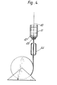
- Figure 4 illustrates the embedding of a composite 40 of seven glass fibres to form a communications filament.
- the composite 40 is formed by unreeling seven fibres from seven reels under constant tension conditions; this part of the process is not shown in the drawing.
- the composite 40 passes into a vertical cylindrical bath 41 which contains the viscous precursor 42 of the elastomeric solid; a constant level is maintained by suitable means (not shown).
- a die 43 is positioned at the base of the bath 41.
- the die 43 has a diameter of Imm.
- the liquid precursor 42 fills the interstital spaces between the sheathed fibres and it (the precursor) is drawn out through the die 43 by the motion of the composite. Because the precursor is viscous it is shaped by the die 43 into a filament of diameter 1mm.
- the filament issuing from die 43 is heated by heater 44 causing the precursor to harden into a solid elastomer. Because the hardening is rapid compared with the flow rate the result is a solid elastomeric filament with external diameter 1mm with seven glass fibres embedded therein. There is an outer layer about 125 ⁇ m thick with no glass fibres. The glass fibres are parallel to the filament axis and contained in a central core of which the diameter is around 750 u m. (Extra layers of "SYLGARD" can be applied, e.g. by repetition of the described coating process. In this way filaments up to 2mm diameter, or larger if required, can be prepared.)
- Fibre is usually supplied in minimum lengths of 2.2km but splicing enables longer lengths, as long as needed, of filament to be prepared. The filament can be tested before incorporation in a cable.
- the communications filament 50 is passed through the centre of a conventional cross-head extruder 51 which produces a polyethylene tube 52 around the filament.
- the extrudate is water, or alternatively air, cooled by coolers 53 to about 100°C and then it passes into the prior annealing oven 54 where the temperature of the extrudate and filament is raised to from 108°C to 112°C over a period of about 2 minutes (the exact temperature is dependent on the precise composition of the extrudate).
- the extrudate passes through drawing die 55.
- the temperature of the drawing die was 100°C for the present example, but again the selected temperature, which must be carefully controlled, is dependent on the extrudate composition.
- the tube 52 is pulled out of drawing die 55 (hence pultrusion) by haul-off 56 running at eight to sixteen times the extrusion speed so that the tube 52 is orientated by stretching in the ratio 1 : 8 to 1 : 16.
- Drawing at such ratios typically leaves a small annular gap between the communications filament 50 and the wall of tube 52. It is necessary to fill this gap with "SYLGARD”. This is achieved by means of capillary tube 57 which extends as far as drawing die 55 and is fed at a constant rate from pressurised hopper 58. "SYLGARD" precursor is introduced into the annular cavity via capillary 57. The residual heat in tube 52 can be employed to cure the precursor achieve cross-linking with the solid elastomer of the filament thereby filling the annular cavity. After drawing the tubular member has a diameter in the range 10 to 20mm.
- submarine cables were prepared using three polymers, namely:-
- the cable may be surrounded by abrasion resistant cladding and electrically conductive members may be incorporated.
- the drawing ratio for the outer tube is not restricted to the 1:8 to 1:16 range described above.
- the outer tube may be drawn tight, slightly compressing the elastomer of the filament, thereby eliminating any gap and obviating the need for further introduction of precursor in such cases.
Landscapes
- Physics & Mathematics (AREA)
- General Physics & Mathematics (AREA)
- Optics & Photonics (AREA)
- Insulated Conductors (AREA)
- Communication Cables (AREA)
- Light Guides In General And Applications Therefor (AREA)
- Laying Of Electric Cables Or Lines Outside (AREA)
- Ropes Or Cables (AREA)
- Addition Polymer Or Copolymer, Post-Treatments, Or Chemical Modifications (AREA)
- Testing Of Optical Devices Or Fibers (AREA)
- Geophysics And Detection Of Objects (AREA)
- Flexible Shafts (AREA)
Priority Applications (1)
| Application Number | Priority Date | Filing Date | Title |
|---|---|---|---|
| AT85308046T ATE54493T1 (de) | 1984-11-15 | 1985-11-05 | Telekommunikationskabel mit optischen fibern. |
Applications Claiming Priority (2)
| Application Number | Priority Date | Filing Date | Title |
|---|---|---|---|
| GB848428878A GB8428878D0 (en) | 1984-11-15 | 1984-11-15 | Telecommunications cable |
| GB8428878 | 1984-11-15 |
Publications (2)
| Publication Number | Publication Date |
|---|---|
| EP0182538A1 true EP0182538A1 (de) | 1986-05-28 |
| EP0182538B1 EP0182538B1 (de) | 1990-07-11 |
Family
ID=10569774
Family Applications (1)
| Application Number | Title | Priority Date | Filing Date |
|---|---|---|---|
| EP85308046A Expired - Lifetime EP0182538B1 (de) | 1984-11-15 | 1985-11-05 | Telekommunikationskabel mit optischen Fibern |
Country Status (10)
| Country | Link |
|---|---|
| US (1) | US4805981A (de) |
| EP (1) | EP0182538B1 (de) |
| JP (1) | JPH0786580B2 (de) |
| AT (1) | ATE54493T1 (de) |
| CA (1) | CA1280306C (de) |
| DE (1) | DE3578639D1 (de) |
| DK (1) | DK165200C (de) |
| ES (2) | ES296767Y (de) |
| GB (1) | GB8428878D0 (de) |
| NO (1) | NO170607C (de) |
Cited By (4)
| Publication number | Priority date | Publication date | Assignee | Title |
|---|---|---|---|---|
| GB2215480A (en) * | 1988-03-04 | 1989-09-20 | Stc Plc | Optical fibre cable element |
| GB2229549A (en) * | 1986-05-17 | 1990-09-26 | Stc Plc | Hydraulic cable installation system |
| WO2001040379A2 (en) * | 1999-11-30 | 2001-06-07 | Corning O.T.I., S.P.A. | Method of fixing a fibre-optic component in an optical device, the optical device so obtained and the polymer composition used therein |
| EP2215508A1 (de) * | 2007-11-26 | 2010-08-11 | Corning Cable Systems LLC | Glasfaserkabel und anordnungen für faser-zu-teilnehmer-anwendungen |
Families Citing this family (13)
| Publication number | Priority date | Publication date | Assignee | Title |
|---|---|---|---|---|
| US4760742A (en) * | 1987-04-10 | 1988-08-02 | Texaco Inc. | Multi-phase petroleum stream monitoring system and method |
| US5042904A (en) * | 1990-07-18 | 1991-08-27 | Comm/Scope, Inc. | Communications cable and method having a talk path in an enhanced cable jacket |
| US5201020A (en) * | 1990-11-08 | 1993-04-06 | Corning Incorporated | Reinforced protective tube for optical waveguide fibers |
| DK0552530T3 (da) * | 1992-01-24 | 1996-09-16 | Alcatel Submarine Systems Bv | Undervandskabelarmering |
| EP0709702A1 (de) * | 1994-10-31 | 1996-05-01 | AT&T Corp. | Verbesserte Kernstruktur für ein faseroptisches Kabel |
| AT2039U1 (de) * | 1996-01-22 | 1998-03-25 | Oekw Oesterreichische Kabelwer | Lichtwellenleiterkabel |
| US6397636B1 (en) | 1999-05-20 | 2002-06-04 | Lucent Technologies Inc. | Method of applying a precursor to an assembled fiber bundle and fusing the bundle together |
| JP2006133666A (ja) * | 2004-11-09 | 2006-05-25 | Mitsumi Electric Co Ltd | 光伝送モジュール及びその製造方法 |
| US8000572B2 (en) * | 2005-05-16 | 2011-08-16 | Schlumberger Technology Corporation | Methods of manufacturing composite slickline cables |
| US7484467B1 (en) * | 2005-06-15 | 2009-02-03 | The United States Of America As Represented By The Secretary Of The Navy | Deep water lift system remote pendant |
| US7920764B2 (en) * | 2007-05-04 | 2011-04-05 | Anthony Stephen Kewitsch | Electrically traceable and identifiable fiber optic cables and connectors |
| WO2013066315A1 (en) * | 2011-11-01 | 2013-05-10 | Empire Technology Development Llc | Cable with optical fiber for prestressed concrete |
| WO2014008123A1 (en) * | 2012-07-03 | 2014-01-09 | Polyone Corporation | Low specific gravity thermoplastic compounds for neutral buoyancy underwater articles |
Citations (2)
| Publication number | Priority date | Publication date | Assignee | Title |
|---|---|---|---|---|
| FR2298807A2 (fr) * | 1975-01-21 | 1976-08-20 | Int Standard Electric Corp | Cable a fibres optiques |
| GB2086607A (en) * | 1980-10-24 | 1982-05-12 | Sumitomo Electric Industries | Coated plastics optical fiber |
Family Cites Families (16)
| Publication number | Priority date | Publication date | Assignee | Title |
|---|---|---|---|---|
| US3766307A (en) * | 1972-08-25 | 1973-10-16 | D Andrews | Buoyant electrical cables |
| GB1371740A (en) * | 1973-03-29 | 1974-10-23 | Standard Telephones Cables Ltd | Coating optical fibres |
| GB1538853A (en) * | 1975-05-14 | 1979-01-24 | Post Office | Dielectric optical waveguides |
| US4113349A (en) * | 1975-07-30 | 1978-09-12 | Air Logistics Corporation | Fiber reinforced optical fiber cable |
| US4228281A (en) * | 1977-09-23 | 1980-10-14 | Ciba-Geigy Corporation | Dicarboxylic acids containing triazine rings |
| DE2907704B2 (de) * | 1979-02-28 | 1981-03-12 | Siemens AG, 1000 Berlin und 8000 München | Verseilelement für optische Kabel |
| DE3069144D1 (en) * | 1979-06-06 | 1984-10-18 | Nat Res Dev | Polymer processing |
| JPS5632109A (en) * | 1979-08-24 | 1981-04-01 | Nippon Telegr & Teleph Corp <Ntt> | Unit type optical fiber cable |
| FR2475238A1 (fr) * | 1980-02-06 | 1981-08-07 | Lyonnaise Transmiss Optiques | Cable a fibres optiques, etanche a l'eau, et procede et dispositif de fabrication de ce cable |
| DE3167332D1 (en) * | 1980-10-01 | 1985-01-03 | Bicc Plc | Method of and arrangement for manufacturing an optical cable element |
| JPS57191603A (en) * | 1981-05-21 | 1982-11-25 | Kokusai Denshin Denwa Co Ltd <Kdd> | Optical fiber unit for submarine cable |
| JPS5895304A (ja) * | 1981-11-23 | 1983-06-06 | オリン・コ−ポレ−シヨン | 光フアイバ−通信ケ−ブルの組立て方法と装置 |
| CA1200062A (en) * | 1981-12-22 | 1986-02-04 | Bicc Public Limited Company | Optical cable elements |
| DE3201981A1 (de) * | 1982-01-22 | 1983-08-04 | Siemens AG, 1000 Berlin und 8000 München | Lichtwellenleitkabel mit umhuellten lichtwellenleitern |
| DE3364039D1 (en) * | 1982-04-02 | 1986-07-17 | Celanese Corp | A melt extruded elongated member of a thermotropic liquid crystalline polymer for use as a stiffening support in an optical fiber cable and fiber optic cables containing such an elongated member |
| JPS60138507A (ja) * | 1983-12-27 | 1985-07-23 | Toyobo Co Ltd | ポリエチレン抗張力線 |
-
1984
- 1984-11-15 GB GB848428878A patent/GB8428878D0/en active Pending
-
1985
- 1985-11-05 AT AT85308046T patent/ATE54493T1/de not_active IP Right Cessation
- 1985-11-05 NO NO854407A patent/NO170607C/no not_active IP Right Cessation
- 1985-11-05 EP EP85308046A patent/EP0182538B1/de not_active Expired - Lifetime
- 1985-11-05 DE DE8585308046T patent/DE3578639D1/de not_active Expired - Lifetime
- 1985-11-07 CA CA000494782A patent/CA1280306C/en not_active Expired - Lifetime
- 1985-11-11 JP JP60252600A patent/JPH0786580B2/ja not_active Expired - Fee Related
- 1985-11-13 ES ES1985296767U patent/ES296767Y/es not_active Expired
- 1985-11-14 DK DK526185A patent/DK165200C/da not_active IP Right Cessation
- 1985-11-15 US US06/798,289 patent/US4805981A/en not_active Expired - Lifetime
-
1986
- 1986-10-31 ES ES557165A patent/ES8707011A1/es not_active Expired
Patent Citations (2)
| Publication number | Priority date | Publication date | Assignee | Title |
|---|---|---|---|---|
| FR2298807A2 (fr) * | 1975-01-21 | 1976-08-20 | Int Standard Electric Corp | Cable a fibres optiques |
| GB2086607A (en) * | 1980-10-24 | 1982-05-12 | Sumitomo Electric Industries | Coated plastics optical fiber |
Non-Patent Citations (1)
| Title |
|---|
| IEEE INTERNATIONAL CONFERENCE ON COMMUNICATIONS, vol. 3, 13th-17th June 1982, pages 7D.4.1-7D.4.3, Philadelphia, US, IEEE, New York, US; G. LE NOANE et al.: "Submarine optical fiber cable development in France" * |
Cited By (7)
| Publication number | Priority date | Publication date | Assignee | Title |
|---|---|---|---|---|
| GB2229549A (en) * | 1986-05-17 | 1990-09-26 | Stc Plc | Hydraulic cable installation system |
| GB2229549B (en) * | 1986-05-17 | 1990-12-19 | Stc Plc | Optical fibre cable for an hydraulic cable installation system |
| GB2215480A (en) * | 1988-03-04 | 1989-09-20 | Stc Plc | Optical fibre cable element |
| WO2001040379A2 (en) * | 1999-11-30 | 2001-06-07 | Corning O.T.I., S.P.A. | Method of fixing a fibre-optic component in an optical device, the optical device so obtained and the polymer composition used therein |
| WO2001040379A3 (en) * | 1999-11-30 | 2001-12-06 | Optical Technologies Italia | Method of fixing a fibre-optic component in an optical device, the optical device so obtained and the polymer composition used therein |
| US6828031B2 (en) | 1999-11-30 | 2004-12-07 | Corning Incorporated | Method of fixing a fiber optic component in an optical device the optical device so obtained and the polymer composition used therein |
| EP2215508A1 (de) * | 2007-11-26 | 2010-08-11 | Corning Cable Systems LLC | Glasfaserkabel und anordnungen für faser-zu-teilnehmer-anwendungen |
Also Published As
| Publication number | Publication date |
|---|---|
| US4805981A (en) | 1989-02-21 |
| ES557165A0 (es) | 1987-07-01 |
| GB8428878D0 (en) | 1984-12-27 |
| NO170607C (no) | 1992-11-04 |
| CA1280306C (en) | 1991-02-19 |
| JPH0786580B2 (ja) | 1995-09-20 |
| ES296767U (es) | 1988-01-16 |
| ES8707011A1 (es) | 1987-07-01 |
| NO170607B (no) | 1992-07-27 |
| EP0182538B1 (de) | 1990-07-11 |
| JPS61122615A (ja) | 1986-06-10 |
| DK526185A (da) | 1986-05-16 |
| DK526185D0 (da) | 1985-11-14 |
| ATE54493T1 (de) | 1990-07-15 |
| DK165200C (da) | 1993-03-01 |
| DE3578639D1 (de) | 1990-08-16 |
| DK165200B (da) | 1992-10-19 |
| NO854407L (no) | 1986-05-16 |
| ES296767Y (es) | 1988-10-01 |
Similar Documents
| Publication | Publication Date | Title |
|---|---|---|
| US4805981A (en) | Telecommunications cable containing optical fibers | |
| US3980808A (en) | Electric cable | |
| CA1167675A (en) | Optical fibre cable | |
| US5230033A (en) | Subminiature fiber optic submarine cable and method of making | |
| US4365865A (en) | Hybrid cable construction | |
| EP1076253B1 (de) | Nachrichtenkabel mit guter Adhesion zwischen Schutzmantel und Verstärkungselementen | |
| US5201020A (en) | Reinforced protective tube for optical waveguide fibers | |
| US6654527B2 (en) | Optical fiber cable | |
| GB2082790A (en) | Optical fibre in grooved central member type cable and manufacture | |
| GB2191872A (en) | Optical fibre cables | |
| US5619606A (en) | Method of manufacturing a reinforced cable containing optical fibers apparatus for implementing the method and a cable obtained by performing the method | |
| GB2064163A (en) | Electro-Optical Cable | |
| GB2046471A (en) | Tube containing optic fibre(s) and thixotropic fluid | |
| CA1225208A (en) | Method for fabricating a cable core including optical fibers | |
| US7313303B2 (en) | Telecommunication cable comprising a jointed optical core and method for jointing said core | |
| GB2296575A (en) | Fibre optic cable ,manufacturing process and plant | |
| US5999677A (en) | Optical fiber cable | |
| GB2065324A (en) | Optical fibres | |
| US4538881A (en) | Optical fiber cable including a strain equalizing adhesive which constrains optical loss | |
| US6853780B1 (en) | Optical cable for telecommunications | |
| US4832441A (en) | Optical fiber cable | |
| GB1568178A (en) | Optical fibre cables | |
| US6500365B1 (en) | Process for the manufacture of an optical core for a telecommunications cable | |
| EP1036344B1 (de) | Hertellungsverfahren für die optische seele eines nachrichtenkabels | |
| CN218728240U (zh) | 一种大芯数防啮齿抗压型光缆 |
Legal Events
| Date | Code | Title | Description |
|---|---|---|---|
| PUAI | Public reference made under article 153(3) epc to a published international application that has entered the european phase |
Free format text: ORIGINAL CODE: 0009012 |
|
| AK | Designated contracting states |
Kind code of ref document: A1 Designated state(s): AT BE CH DE FR GB IT LI LU NL SE |
|
| 17P | Request for examination filed |
Effective date: 19861030 |
|
| 17Q | First examination report despatched |
Effective date: 19871221 |
|
| RAP3 | Party data changed (applicant data changed or rights of an application transferred) |
Owner name: BRITISH TELECOMMUNICATIONS PUBLIC LIMITED COMPANY |
|
| REG | Reference to a national code |
Ref country code: GB Ref legal event code: 732 |
|
| GRAA | (expected) grant |
Free format text: ORIGINAL CODE: 0009210 |
|
| AK | Designated contracting states |
Kind code of ref document: B1 Designated state(s): AT BE CH DE FR GB IT LI LU NL SE |
|
| REF | Corresponds to: |
Ref document number: 54493 Country of ref document: AT Date of ref document: 19900715 Kind code of ref document: T |
|
| ITF | It: translation for a ep patent filed |
Owner name: JACOBACCI & PERANI S.P.A. |
|
| REF | Corresponds to: |
Ref document number: 3578639 Country of ref document: DE Date of ref document: 19900816 |
|
| ET | Fr: translation filed | ||
| PLBE | No opposition filed within time limit |
Free format text: ORIGINAL CODE: 0009261 |
|
| STAA | Information on the status of an ep patent application or granted ep patent |
Free format text: STATUS: NO OPPOSITION FILED WITHIN TIME LIMIT |
|
| 26N | No opposition filed | ||
| ITTA | It: last paid annual fee | ||
| EPTA | Lu: last paid annual fee | ||
| EAL | Se: european patent in force in sweden |
Ref document number: 85308046.3 |
|
| REG | Reference to a national code |
Ref country code: CH Ref legal event code: PUE Owner name: BRITISH TELECOMMUNICATIONS PUBLIC LIMITED COMPANY |
|
| NLS | Nl: assignments of ep-patents |
Owner name: CABLE & WIRELESS PLC |
|
| REG | Reference to a national code |
Ref country code: FR Ref legal event code: TP |
|
| REG | Reference to a national code |
Ref country code: GB Ref legal event code: 732E |
|
| REG | Reference to a national code |
Ref country code: GB Ref legal event code: 732E |
|
| BECA | Be: change of holder's address |
Free format text: 20000928 *GLOBAL MARINE SYSTEMS LTD:EAST SAXON HOUSE 27 DUKE STREET, CHELMSFORD ESSEX CM1 1HT |
|
| BECN | Be: change of holder's name |
Effective date: 20000928 |
|
| NLS | Nl: assignments of ep-patents |
Owner name: CABLE & WIRELESS MARINE LIMITED |
|
| NLT1 | Nl: modifications of names registered in virtue of documents presented to the patent office pursuant to art. 16 a, paragraph 1 |
Owner name: GLOBAL MARINE SYSTEMS LIMITED |
|
| REG | Reference to a national code |
Ref country code: FR Ref legal event code: TP Ref country code: FR Ref legal event code: CD |
|
| REG | Reference to a national code |
Ref country code: GB Ref legal event code: IF02 |
|
| PGFP | Annual fee paid to national office [announced via postgrant information from national office to epo] |
Ref country code: GB Payment date: 20021030 Year of fee payment: 18 |
|
| PGFP | Annual fee paid to national office [announced via postgrant information from national office to epo] |
Ref country code: SE Payment date: 20021106 Year of fee payment: 18 |
|
| PGFP | Annual fee paid to national office [announced via postgrant information from national office to epo] |
Ref country code: DE Payment date: 20021107 Year of fee payment: 18 |
|
| PGFP | Annual fee paid to national office [announced via postgrant information from national office to epo] |
Ref country code: FR Payment date: 20021108 Year of fee payment: 18 |
|
| PGFP | Annual fee paid to national office [announced via postgrant information from national office to epo] |
Ref country code: LU Payment date: 20021113 Year of fee payment: 18 Ref country code: AT Payment date: 20021113 Year of fee payment: 18 |
|
| PGFP | Annual fee paid to national office [announced via postgrant information from national office to epo] |
Ref country code: CH Payment date: 20021115 Year of fee payment: 18 |
|
| PGFP | Annual fee paid to national office [announced via postgrant information from national office to epo] |
Ref country code: NL Payment date: 20021129 Year of fee payment: 18 |
|
| PGFP | Annual fee paid to national office [announced via postgrant information from national office to epo] |
Ref country code: BE Payment date: 20030117 Year of fee payment: 18 |
|
| REG | Reference to a national code |
Ref country code: CH Ref legal event code: PUE Owner name: CABLE & WIRELESS MARINE LIMITED Free format text: CABLE & WIRELESS PLC#124 THEOBALDS ROAD#LONDON WC1X 8RX (GB) -TRANSFER TO- CABLE & WIRELESS MARINE LIMITED#EAST SAXON HOUSE, 27 DUKE STREET#CHELMSFORD, ESSEX CM1 1HT (GB) Ref country code: CH Ref legal event code: PFA Owner name: GLOBAL MARINE SYSTEMS LIMITED Free format text: CABLE & WIRELESS MARINE LIMITED#EAST SAXON HOUSE, 27 DUKE STREET#CHELMSFORD, ESSEX CM1 1HT (GB) -TRANSFER TO- GLOBAL MARINE SYSTEMS LIMITED#EAST SAXON HOUSE, 27 DUKE STREET#CHELMSFORD, ESSEX CM1 1HT (GB) |
|
| REG | Reference to a national code |
Ref country code: CH Ref legal event code: NV Representative=s name: ISLER & PEDRAZZINI AG |
|
| PG25 | Lapsed in a contracting state [announced via postgrant information from national office to epo] |
Ref country code: LU Free format text: LAPSE BECAUSE OF NON-PAYMENT OF DUE FEES Effective date: 20031105 Ref country code: GB Free format text: LAPSE BECAUSE OF NON-PAYMENT OF DUE FEES Effective date: 20031105 Ref country code: AT Free format text: LAPSE BECAUSE OF NON-PAYMENT OF DUE FEES Effective date: 20031105 |
|
| PG25 | Lapsed in a contracting state [announced via postgrant information from national office to epo] |
Ref country code: SE Free format text: LAPSE BECAUSE OF NON-PAYMENT OF DUE FEES Effective date: 20031106 |
|
| PG25 | Lapsed in a contracting state [announced via postgrant information from national office to epo] |
Ref country code: LI Free format text: LAPSE BECAUSE OF NON-PAYMENT OF DUE FEES Effective date: 20031130 Ref country code: CH Free format text: LAPSE BECAUSE OF NON-PAYMENT OF DUE FEES Effective date: 20031130 Ref country code: BE Free format text: LAPSE BECAUSE OF NON-PAYMENT OF DUE FEES Effective date: 20031130 |
|
| BERE | Be: lapsed |
Owner name: *GLOBAL MARINE SYSTEMS LTD Effective date: 20031130 |
|
| PG25 | Lapsed in a contracting state [announced via postgrant information from national office to epo] |
Ref country code: NL Free format text: LAPSE BECAUSE OF NON-PAYMENT OF DUE FEES Effective date: 20040601 |
|
| PG25 | Lapsed in a contracting state [announced via postgrant information from national office to epo] |
Ref country code: DE Free format text: LAPSE BECAUSE OF NON-PAYMENT OF DUE FEES Effective date: 20040602 |
|
| GBPC | Gb: european patent ceased through non-payment of renewal fee |
Effective date: 20031105 |
|
| EUG | Se: european patent has lapsed | ||
| REG | Reference to a national code |
Ref country code: CH Ref legal event code: PL |
|
| PG25 | Lapsed in a contracting state [announced via postgrant information from national office to epo] |
Ref country code: FR Free format text: LAPSE BECAUSE OF NON-PAYMENT OF DUE FEES Effective date: 20040730 |
|
| NLV4 | Nl: lapsed or anulled due to non-payment of the annual fee |
Effective date: 20040601 |
|
| REG | Reference to a national code |
Ref country code: FR Ref legal event code: ST |