EP0182528A2 - Apparatus for assembling terminated wires into connectors to form electrical harnesses - Google Patents
Apparatus for assembling terminated wires into connectors to form electrical harnesses Download PDFInfo
- Publication number
- EP0182528A2 EP0182528A2 EP85307936A EP85307936A EP0182528A2 EP 0182528 A2 EP0182528 A2 EP 0182528A2 EP 85307936 A EP85307936 A EP 85307936A EP 85307936 A EP85307936 A EP 85307936A EP 0182528 A2 EP0182528 A2 EP 0182528A2
- Authority
- EP
- European Patent Office
- Prior art keywords
- wires
- connectors
- termination
- station
- connector
- Prior art date
- Legal status (The legal status is an assumption and is not a legal conclusion. Google has not performed a legal analysis and makes no representation as to the accuracy of the status listed.)
- Granted
Links
Images


Classifications
-
- H—ELECTRICITY
- H01—ELECTRIC ELEMENTS
- H01R—ELECTRICALLY-CONDUCTIVE CONNECTIONS; STRUCTURAL ASSOCIATIONS OF A PLURALITY OF MUTUALLY-INSULATED ELECTRICAL CONNECTING ELEMENTS; COUPLING DEVICES; CURRENT COLLECTORS
- H01R43/00—Apparatus or processes specially adapted for manufacturing, assembling, maintaining, or repairing of line connectors or current collectors or for joining electric conductors
- H01R43/28—Apparatus or processes specially adapted for manufacturing, assembling, maintaining, or repairing of line connectors or current collectors or for joining electric conductors for wire processing before connecting to contact members, not provided for in groups H01R43/02 - H01R43/26
-
- H—ELECTRICITY
- H01—ELECTRIC ELEMENTS
- H01R—ELECTRICALLY-CONDUCTIVE CONNECTIONS; STRUCTURAL ASSOCIATIONS OF A PLURALITY OF MUTUALLY-INSULATED ELECTRICAL CONNECTING ELEMENTS; COUPLING DEVICES; CURRENT COLLECTORS
- H01R43/00—Apparatus or processes specially adapted for manufacturing, assembling, maintaining, or repairing of line connectors or current collectors or for joining electric conductors
- H01R43/01—Apparatus or processes specially adapted for manufacturing, assembling, maintaining, or repairing of line connectors or current collectors or for joining electric conductors for connecting unstripped conductors to contact members having insulation cutting edges
-
- H—ELECTRICITY
- H01—ELECTRIC ELEMENTS
- H01R—ELECTRICALLY-CONDUCTIVE CONNECTIONS; STRUCTURAL ASSOCIATIONS OF A PLURALITY OF MUTUALLY-INSULATED ELECTRICAL CONNECTING ELEMENTS; COUPLING DEVICES; CURRENT COLLECTORS
- H01R43/00—Apparatus or processes specially adapted for manufacturing, assembling, maintaining, or repairing of line connectors or current collectors or for joining electric conductors
- H01R43/04—Apparatus or processes specially adapted for manufacturing, assembling, maintaining, or repairing of line connectors or current collectors or for joining electric conductors for forming connections by deformation, e.g. crimping tool
- H01R43/048—Crimping apparatus or processes
- H01R43/052—Crimping apparatus or processes with wire-feeding mechanism
-
- Y—GENERAL TAGGING OF NEW TECHNOLOGICAL DEVELOPMENTS; GENERAL TAGGING OF CROSS-SECTIONAL TECHNOLOGIES SPANNING OVER SEVERAL SECTIONS OF THE IPC; TECHNICAL SUBJECTS COVERED BY FORMER USPC CROSS-REFERENCE ART COLLECTIONS [XRACs] AND DIGESTS
- Y10—TECHNICAL SUBJECTS COVERED BY FORMER USPC
- Y10T—TECHNICAL SUBJECTS COVERED BY FORMER US CLASSIFICATION
- Y10T29/00—Metal working
- Y10T29/49—Method of mechanical manufacture
- Y10T29/49002—Electrical device making
- Y10T29/49117—Conductor or circuit manufacturing
- Y10T29/49174—Assembling terminal to elongated conductor
-
- Y—GENERAL TAGGING OF NEW TECHNOLOGICAL DEVELOPMENTS; GENERAL TAGGING OF CROSS-SECTIONAL TECHNOLOGIES SPANNING OVER SEVERAL SECTIONS OF THE IPC; TECHNICAL SUBJECTS COVERED BY FORMER USPC CROSS-REFERENCE ART COLLECTIONS [XRACs] AND DIGESTS
- Y10—TECHNICAL SUBJECTS COVERED BY FORMER USPC
- Y10T—TECHNICAL SUBJECTS COVERED BY FORMER US CLASSIFICATION
- Y10T29/00—Metal working
- Y10T29/51—Plural diverse manufacturing apparatus including means for metal shaping or assembling
- Y10T29/5136—Separate tool stations for selective or successive operation on work
- Y10T29/5137—Separate tool stations for selective or successive operation on work including assembling or disassembling station
- Y10T29/5139—Separate tool stations for selective or successive operation on work including assembling or disassembling station and means to sever work prior to disassembling
-
- Y—GENERAL TAGGING OF NEW TECHNOLOGICAL DEVELOPMENTS; GENERAL TAGGING OF CROSS-SECTIONAL TECHNOLOGIES SPANNING OVER SEVERAL SECTIONS OF THE IPC; TECHNICAL SUBJECTS COVERED BY FORMER USPC CROSS-REFERENCE ART COLLECTIONS [XRACs] AND DIGESTS
- Y10—TECHNICAL SUBJECTS COVERED BY FORMER USPC
- Y10T—TECHNICAL SUBJECTS COVERED BY FORMER US CLASSIFICATION
- Y10T29/00—Metal working
- Y10T29/51—Plural diverse manufacturing apparatus including means for metal shaping or assembling
- Y10T29/5136—Separate tool stations for selective or successive operation on work
- Y10T29/5137—Separate tool stations for selective or successive operation on work including assembling or disassembling station
- Y10T29/5142—Separate tool stations for selective or successive operation on work including assembling or disassembling station and means to sever work from supply
-
- Y—GENERAL TAGGING OF NEW TECHNOLOGICAL DEVELOPMENTS; GENERAL TAGGING OF CROSS-SECTIONAL TECHNOLOGIES SPANNING OVER SEVERAL SECTIONS OF THE IPC; TECHNICAL SUBJECTS COVERED BY FORMER USPC CROSS-REFERENCE ART COLLECTIONS [XRACs] AND DIGESTS
- Y10—TECHNICAL SUBJECTS COVERED BY FORMER USPC
- Y10T—TECHNICAL SUBJECTS COVERED BY FORMER US CLASSIFICATION
- Y10T29/00—Metal working
- Y10T29/51—Plural diverse manufacturing apparatus including means for metal shaping or assembling
- Y10T29/5193—Electrical connector or terminal
-
- Y—GENERAL TAGGING OF NEW TECHNOLOGICAL DEVELOPMENTS; GENERAL TAGGING OF CROSS-SECTIONAL TECHNOLOGIES SPANNING OVER SEVERAL SECTIONS OF THE IPC; TECHNICAL SUBJECTS COVERED BY FORMER USPC CROSS-REFERENCE ART COLLECTIONS [XRACs] AND DIGESTS
- Y10—TECHNICAL SUBJECTS COVERED BY FORMER USPC
- Y10T—TECHNICAL SUBJECTS COVERED BY FORMER US CLASSIFICATION
- Y10T29/00—Metal working
- Y10T29/53—Means to assemble or disassemble
- Y10T29/5313—Means to assemble electrical device
- Y10T29/532—Conductor
- Y10T29/53209—Terminal or connector
- Y10T29/53213—Assembled to wire-type conductor
- Y10T29/53217—Means to simultaneously assemble multiple, independent conductors to terminal
Definitions
- the present invention relates to apparatus for assembling terminated wires into electrical connectors to form harnesses.
- the object of the present invention is to provide an improved apparatus for the semi-automatic or automatic manufacture of such harnesses.
- an apparatus for assembling terminated wires into connectors to form electrical harnesses includes a connector loading station whereat connectors are initially positioned, a termination station spaced from said loading station whereat connectors are terminated to wires, means for moving connectors from said loading station to said termination station, means for presenting wire ends to said termination station so that the wires are aligned with terminals of said connectors, and a termination head for mass inserting said wires in said terminals, said connector moving means comprising a shuttle table system including a plurality of coplanar tables movable in a common closed rectilinear path between said connector loading and terminating stations, at least one table having connector carrying means thereon.
- the shuttle tables may be moved rapidly from one station to the next.
- the tables may be made to occupy very little space with the resulting benefit that the size of the apparatus may be reduced.
- the connector carrying means may conveniently comprise an elongated, slotted track-like fixture.
- the apparatus further comprises a connector eject station disposed on said path opposing said loading station, whereat connectors are loaded onto an eject track.
- an apparatus for assembling terminated wires into electrical connectors to form harnesses includes a connector loading station whereat connectors are initially positioned, a termination station spaced from said loading station whereat connectors are terminated to wires, means for moving said connectors from said loading station to said termination station, means for presenting wire ends to said termination station so that wires are aligned with terminals of said connectors, a termination head for mass inserting said wires in said terminals, feed means including a feed member movable between a feed track and said loading station, having a plurality of engaging means for mating with complementary engaging means on the connectors to engage and align said connectors with said feed member, and means for moving said feed member to said loading station to thereby deliver connectors engaged and aligned with said feed member to a predetermined initial position at said loading station.
- the feed member includes a track-like portion aligned with a table fixture at said loading station to form therewith a continuous path of connector travel and preferably also said feed member comprises a plate having an edge carrying said engaging means, mounted for reciprocation between said feed track and a table fixture located at said loading station, said plate being mounted for rotation between said loading station and said eject station.
- the apparatus may further comprise an eject track aligned with a table fixture at said eject station to form therewith a continuous path of connector travel.
- said plate when rotated towards said eject station may be operable to engage connectors located in a table fixture thereat, with subsequent reciprocations of said plate advancing said connectors along said eject track.
- An apparatus of the present invention may include a selectively adjustable slit and insertion blade unit for slitting ribbon cable and inserting the individual wires of the cable into an insulation displacement terminal connector positioned at an insertion station of the apparatus. This has the advantage of simplifying the operation of p re-notching the ribbon cable in advance of the insertion station.
- an apparatus for assembling terminated wires into connectors to form electrical harnesses includes a connector loading station whereat connectors are intitially positioned, a termination station spaced from said loading station whereat connectors are terminated to wires, means for moving connectors from said loading station to said termination station, means i for presenting a flat multi-conductor ribbon cable end to said termination station so that the cable wires are aligned with terminals of said connectors, and a termination head for mass inserting said wires in said terminals, said termination head comprising an alternating sequence of conductor insertion blades and web splitting blades mounted for simultaneous movement, said conductor insertion blades being aligned with wires of said cable end, and said web splitting blades being aligned with web portions of said cable between adjacent wires, whereby upon downward movement of the termination head said conductor insertion and web splitting blades simultaneously engage said wires and web portions, respectively, to mass insert said wires in said terminals.
- An apparatus of the present invention may still further include a selectively adjustable connector separation unit for separating connectors from chain molded connector sticks fed into the apparatus.
- an apparatus for assembling terminated wires into connectors to form electrical harnesses includes a connector loading station whereat sticks of connectors are initially positioned, a termination station spaced from said loading station whereat connectors are terminated to wires, means for moving connector sticks from said loading station to said termination station, means for presenting wire ends to said termination station so that the wires are aligned with terminals of said connectors, a termination head for mass inserting said wires in said terminals, and stick separation means operatively associated with said connector stick after wire insertion for separating said connector sticks to form a plurality of independent harnesses, the stick separation means comprising a base member movable toward said connector sticks, a plurality of punches mounted on said base member and aligned with portions of said connector sticks so as to be selectively movable between an operative position for contacting said connector stick portions, and a second inoperative retracted position, and a cover overlying said punches and engaging said base member,
- the present invention still further includes an apparatus for assembling terminated wires into connectors to form electrical harnesses having connectors one at each end including connector loading stations whereat connectors are initially positioned, spaced-apart termination stations, remote from said loading stations, whereat connectors are terminated to wires, means for moving connectors from said loading stations to said termination stations, means for presenting the respective ends of a predetermined length of a predetermined number of wires to said termination stations so that the wires are aligned with terminals of said connectors, including means for feeding a predetermined length of a predetermined number of wires from a supply of wires, means for severing said predetermined length of wires from said supply, and means for presenting respective ends of said wires to each of said termination stations, said presenting means comprising a pair of presenting wire guides movable from initial positions to extended positions between said termination stations, a carriage wire guide located at an initial position beside said pair of presenting wire guides, operative to engage a free end of wires from said wire supply and to travel from said
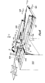
- the apparatus comprises left and right hand shuttle table towers, generally indicated at 100 and 101 respectively spaced apart and relatively movable towards and away from one another by means of a lead screw 102 to select the length of the harnesses to be assembled.
- Each tower is topped by a shuttle table system 104, 104a made up of three, square, shuttle tables 106 which are movable in turn, and in a following sequence, one with respect to another, as indicated by the arrows G F E H in figs. 2 and 4, that is to say, into successive ones of four positions around a closed, rectilinear, square-form path.
- the respective shuttle table systems 104, 104a operate in opposite directions of movement, the tables of the left hand system 104 as seen in Figs. 1 to 4 moving clockwise, and the tables of the right hand system as seen in Figs. 1 to 4 moving anti-clockwise.
- Each table makes a purely linear movement in its turn, the tables moving in the directions indicated by the arrows G F E H, and each table carries an elongated, slotted track-like fixture 110 having a track for positioning individual connectors or a stick or sticks of interconnected connectors s, the fixtures 110 being carried by the tables with their tracks all in parallel with one another, those fixtures 110 of the left hand shuttle table system 104 being positioned each along the right hand edge of its table and those fixtures 110 of the right hand shuttle table system 104a being positioned each along the left hand edge of its table.
- the shuttle table systems 104, 104a have their table fixtures 110 moved successively, in the directions indicated by arrows F into connector loading stations f, e.g. in which sticks of connectors are loaded into the fixture tracks, then in the directions indicated by arrows E into void positions e, then in the directions indicated by arrows H into termination stations h, in which wires w are terminated into sticks of connectors, then in the directions indicated by arrows G into test and eject stations g in which the assembled harnesses are tested and then unloaded from the fixture tracks onto an eject track.
- each shuttle table system 104, 104a Associated with each shuttle table system 104, 104a is a linearly movable feed/location member in the form of a plate 112 carried by a rotating actuator 114 mounted on a pneumatically operated slide 115 to slide to-and-fro in the directions of arrows E and G and as indicated by the double-headed arrow C in Figs. 2 and 4.
- the actuator 114 is actuable to position the plate 112 alternately over the loading station f and the eject station g, as indicated by the double-headed arrow B.
- the plate 112 has a row of location teeth 116 on each side to locate in the wire receiving recesses 161 (see Figs.
- the rows of teeth 116 are predeterminedly spaced to engage one tooth in each of the connector stick recesses 161, there being a recess 161 formed at each circuit point of each connector stick.
- the teeth 116 therefore, engage with the connector sticks s to entrain the connector sticks for loading and, thereafter, unloading movements along the fixture tracks as the actuator 114 is slid to-and-fro in the directions C+ and C- respectively, the actuator having previously been actuated to rotate the plate 112 in the directions B+ and B- respectively.
- a pre-position shuttle and component load actuator 120 which carries a track block having a track 121 for guiding sticks of connectors s parallel with the tracks of the fixtures 110 mounted on the shuttle tables.
- Each actuator 120 is mounted on a pneumatically operated slide so as to be slidable to-and-fro in the directions of arrows H and F as indicated by the double headed arrow A in the direction A+ to align its connector stick track respectively with that of a fixture 110 in the loading station f and in the direction A- to align its connector stick track with a connector stick loading track 124 parallel to, but outwardly offset, with respect to the fixtures 110 positioned at the loading stations f.
- Eject tracks 126 are provided for the connectors s of the assembled harnesses, these aligning with the tracks of the fixtures 110 positioned at the test and eject stations 9 .
- Connectors or connector sticks s may be loaded into the loading tracks by means of a bowl feed, a tape reel feed, or by hand.
- tape feed and bowl feed mechanisms are indicated respectively at 130 and 131 in fig. 3.
- Wire feed may be from reels of discrete wires w, or ribbon cable may be used.
- Discrete wires w are fed in over a changeover drum 134 (see Fig. 3), for measuring the wires, the drum being selected according to the size of the wires w, and then through a wire straightener 135.
- the wires are fed in transversely of the loading and eject tracks 124, 126 behind the shuttle table towers 100, 101 and are mechanically handled by wire guides 201, 202, 203 and 204 indicated diagrammatically in Fig. 2.
- the carriage wire guide 201 is carried for transverse movements, between a fixed position 201A and a selectable position 201B, by a carriage 136 movable to-and-fro on track rods 137 (see Fig. 1), and this guide moves between the jaws of the wire cutting station guide 204 when the wire guide 204 is open.
- the position 201B of the carriage wire guide is selected depending upon the spacing of the right hand tower 101 from the left hand tower 100 and the positions 201A and 201B remain in the same position as shown in Fig. 2, relative to the towers 100, 101 respectively.
- the wire guide 204 is movable between two positions fixed relative to the tower 100, as shown in Fig.
- the left and right hand wire guides 202 and 203 associated with the left and right hand towers 100, 101 respectively, are movable to-and-fro in the lengthwise direction of the loading and unloading tracks 124, 126.
- the guide 202 has a rearmost position 202A out of the path of movement of the carriage 136, a second wire gripping position 202B on which it aligns transversely with the wire guides 201 and 204 on the inboard side of the positions 201A, 204B and 204A and a third or forward- most position 202C in which it aligns with the wire termination station h of the left hand shuttle table system 100 on the inboard side.
- the guide 203 has two positions 203A and 203B which it always maintains relative to the tower 101, corresponding to the positions 202B and 202C respectively, and the guides 202 and 203 move between their positions 202B, 203A and 202C, 203B in unison.
- the wires w are fed through the wire guide 201 positioned at 201A and are overfed through wire guide 204 with the guide 204 in the position 204A, that is to say, in its position to grip the wires during the wire cutting by the wire cutter Z.
- the guide 204 is not closed at this stage.
- the left and right hand guides 202 and 203 are open and positioned at 202A and 203A respectively.
- the guide 201A is closed to grip the wires and the wire cutter Z is operated to cut the wires w, thereby to align the ends of the wires at the wire cutting station z.
- the wire guides are automatically sequenced as follows:-Guide 201 moves from 201A to 201B to transport the cut wire ends to align with the right hand termination station h. The wires are overfed through the guide 203 which then closes to grip the wires. Guide 201 then opens and moves back to 201A and recloses. At this stage, the wire ends, gripped by the guide 203, may be operated upon by a single ended wire insulation stripper unit T. In the present example, however, it is assumed that an I.D.T. connector is being used at each end. Next, the wire guide 202 moves to 202B and closes, gripping the wires adjacent the left hand tower 100.
- the wire guide 204A closes and required lengths of harness wires w are cut off from the feed wires at the station z.
- the wire guide 201 opens and the wire guide 204 moves to 204B retracting the feed wire ends.
- the wire guides 202 and 203 move in unison to 202C and 203B respectively to position the harness wire ends at the wire insertion stations h. Termination presses P carried one over each of the shuttle table towers are then operated to terminate the wires in connector sticks s positioned at the termination stations h.
- the wire guides 202 and 203 open and move to positions 202A and 203A respectively.
- the wire guide 204 moves to 204A.
- the carriage wire guide 201 closes on the feed wires w at the input feed. At the same time the wire guide 204 opens to allow the passage of the carriage wire guide to the position 201B as the automatic wire feed cycle re-commences.
- the cable may be fed through a wire measure and notching tool M. It is proposed, however, that pre-notching of the cable be dispensed with by using the web splitting/conductor inserting blade unit which is yet to be described.
- movements of the shuttle tables 106 of each of the shuttle table systems 104, 104a are accomplished using four stepper motors 140 each of which drives a shaft 141.
- a gear train 143, 144, 145, 146, one for each shaft 141 drives a dual track cam 148, one for each shaft.
- the cams 148 are positioned correspondingly, one beneath each of the shuttle table stations and each cam is operated, in turn, to shift a shuttle table to the next following station, the axes of adjacent cams 148 being disposed in the same horizontal plane at right angles to one another as seen in Fig. 5.
- each stepper motor 140 is repositioned and has a rubber timing belt to transmit the drive from the stepper motor shaft 141 to its associated cam 148.
- the cams are shaped and positioned to shift the tables of the left hand shuttle table tower clockwise.
- a reflection of the cam form and cam positions is adopted in an arrangement as shown in Figs. 5 to 7 to shift the tables 106 of the right hand shuttle table tower anti-clockwise and will not be further described.
- the shuttle tables 106 each comprise a lower keeper plate 149 fixed thereto, the tables being confined to slide in their rectilinear, square-form path on inner and outer guides 150 and 151.
- Each table 106 carries centrally, a concentric pair of roller followers 152, 153, the smaller one 152 of which engages in helical cam grooves 154 and the larger one 153 of which engages with helical cam faces 155 on formations 156 of the cams 148.
- the cam faces 155 of each cam engage the follower 153 as the follower 152 leaves the cam groove 154 of the cam, to shift the follower 152 into the cam groove 154 of the next following cam 148.
- each cam groove 154 has an initial, circumferential lead-in portion 154' best seen in Fig. 5.
- the diameter of the followers 153 is chosen sufficient to shift the follower 152 through the full extent of this lead-in portion of the next following cam 148 so that the shuttle plate is set in its next following station for immediate onward movement when the next following cam 148 is driven in rotation by its shaft 142 and gear train 143 to 146.
- the cams In order to operate an optional six position shuttle table system as diagrammatically illustrated for the right hand shuttle tower in Fig. 2 employing four shuttle tables 106' and two void stations e 1 , and e 2' the cams would be arranged in two oppositely facing, parallel pairs disposed at right angles, the pair of cams disposed along the short sides H and F of the rectilinear path of movement taking the form of the cams 148 alreading described and the pair of cams (not shown) disposed along the long sides GlG2 and ElE2 of the rectilinear paths of movement being of double length and having helical cam grooves 154 of double lengthwise extent, compared with the cams 148, and with intermediate, circumferential dwell portions corresponding with their lead-in portions 154'.
- This arrangement provides an additional operating station g2 (see Fig. 2) at which, for example, an overhead separation press might be provided to separate a multiple connector s in two or more connector parts and from which the separated parts would be unloaded in the manner already described.
- an overhead separation press might be provided to separate a multiple connector s in two or more connector parts and from which the separated parts would be unloaded in the manner already described.
- a separator press might be positioned above an "off-shuttle-table station" into which connectors are unloaded, and positioned, by the actuator 114.
- the six position shuttle table system still has its loading and eject stations f and g2 disposed alongside one another on opposite sides of the closed rectilinear path of movement of the tables indicated by the arrows El, E2, H, G1G2, F so that the actuator 114 can still operate alternately at these stations, as described above.
- the station Gl becomes simply a testing station in this case.
- each shuttle plate fixture 110 comprises a base plate 156, a track block 157 which, together with a location plate 158, defines a track in which sticks of connectors s may be positively located by teeth 159 on the location plate.
- the teeth 159 are spaced apart to interfit with grooves 160 moulded in the inboard face of the connector sticks s, one such groove 160 aligning with each wire receiving recess 161 previously described.
- the teeth 159 are predeterminedly spaced to engage one tooth in each of the connector stick grooves 160.
- the track block 157 is located with respect to,and fixed to,the base plate 156 by dowels and screws and defines a central recess 162 in its lower face which houses a slide 163 which slides on the base plate and which carries the location plate 158 at one of its longitudinal edges, the slide having an abutment flange 164 at its opposite longitudinal edge which engages compression springs 165 partially housed in bores in the track block.
- the springs 165 urge the location plate 158 into its locating relation and the slide 163 is movable against the action of the springs 165 to displace the location plate and thereby release connector sticks s located in the fixture track, for unloading lengthwise from the track by the actuator 114 as already described, and to open the track to receive connector sticks loaded lengthwise into the track by the actuator 114, as already described.
- the slide fixedly mounts a transverse tenon 166 which is guided for sliding movement in a transverse groove 167 in the track block 157.
- the tenon carries a roller follower 167'for operating the slide in proper sequence as described below.
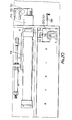
- the web splitting/conductor inserting blade unit 168 shown in Figs. 11, 12 and 13 is intended for splitting the ends of ribbon cable and inserting the separated insulation covered ends of the wires in IDT connectors.
- the unit comprises alternate splitting and insertion blades 169' and 170' formed on respective blade parts 169 and 170.
- the slitting blades 169' which are sharp edged,are received each between an adjacent pair of insertion blades 170' and the slitting blade part 169 is slidable relative to the insertion blade part 170, the slitting blade part 169 being guided for sliding movement between a back plate 171 and the insertion blade part which is located with respect to, and fixed to, the back plate, there being a spacer 172 located and fixed therebetween having bores housing compression springs 173 urging the slitting blade part to project its blades' cutting edges 169" beyond the insertion edges 170" of the insertion blades 170 1 .
- a flange 169a on the slitting blade part engages a stop (not shown) when the termination press P carrying the unit 168 is operated to limit the downward movement of the slitting blade part 169 whereby slitting of the ribbon cable webs is accomplished against the underlying connector stick housings without damage to the housing at the termination station being operated.
- the configuration of the insertion edges 170" which are radiused in cross-section to receive the insulation covered wires, is chosen to suit the form of the connector housings and insulation displacement terminals of the connector sticks as will be well understood, in all so as to insert the wires fully into the insulation displacement terminals and between strain relieving gripping formations of the housings.
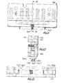
- the stick separation means 172 shown in Figs. 14, 15 and 16 is intended for use at a component separation station U (see Fig. 4) of the apparatus for severing stick connectors into separate connector components at circuit points left void in the connector sticks. It may, however, alternatively be employed as an insertion blade unit for inserting discrete wires at an insertion station of the apparatus, e.g. to apply wires into I.D.T. connectors in multiples or, again, for pre-loading series of connectors with voids between certain groups of connectors into the apparatus and, in conjunction with the actuator 114, for unloading such series from the unloading station of the apparatus.
- the unit 172 is made up of twenty two punches 173 rotatably mounted on a hinge pin 174 fixed in a base member 176 to enable selected ones of the punches to be swung between an operative position shown in full line in figs. 14 and 15 and an inoperative or retracted position shown in dotted line in Fig. 15.
- the unit has a removable cover 177 which, when in position, engages with one or other (see Fig. 18) of the edges 173' or 173" of the punches to retain the punches in their selected operative or inoperative positions.
- Set screws 178 are employed to retain the hinge pin 174 in position and to fix the pin against rotation in the base 176.
- the punches are positively positioned at their edges 173' and 173" between the cover 177 and the base.
- the punches are numbered, as at 178, both on the cover and again on the base behind the cover to enable the unit to be programmed for setting up the apparatus with selected punches as required.
- the punches are formed with V-form cutting edges and may be used to crop and separate connectors or connector sticks joined into chains by pin and hole coupling formations as described in our Application No. 8330617.
- Figs. 19 and 20 show a further linearly movable component unload release slide 180 of which one is associated with each shuttle table system 104, 104a.
- the slide 180 like the slide 112 is operated by a pneumatic cylinder 181 and is mounted to slide in the direction of arrows E and G as indicated by the double-headed arrow D in Fig. 4, and in the direction D+ to engage its finger 180' with the roller follower 167 ' of the fixture 110 located at the unloading station g or g2 of the shuttle table system to displace its slide 163 by camming action against the action of the springs 165 and thereby release a component held in the fixture for unloading from the fixture.
- the slide 180 is moved in the direction D- the finger 180' disengages the roller follower 167'and the fixture track is returned to its closed condition by its springs 165.
- the pre-position shuttle component load actuator 120 likewise has a finger 185 to engage and force back the slide of the fixture 110 at the loading station f to open the track of the fixture to allow a component or components to be loaded into the track by the actuator 114.
- the pre-position shuttle and component load actuator 120 In the initial setting of the apparatus the pre-position shuttle and component load actuator 120 is displaced to its A- position (see Fig. 4), the actuator 114 is in its C- position with its flap 112 in the B- position and the component unload release slide is in its D- position.
- the apparatus is operated to load and unload the apparatus and to shift the shuttle tables 106 on both sides of the apparatus in the following tabulated, automatically controlled, sequence of steps:-
- the apparatus includes an electronic control system of any known or convenient construction prgrammed to sequence the operation of the apparatus.
- the stepper motors 140 are sequenced by the system to achieve simultaneous movements of the shuttle tables of the systems 104, 104a.
Abstract
Description
- The present invention relates to apparatus for assembling terminated wires into electrical connectors to form harnesses.
- In order to conduct electrical signals between printed circuit board assemblies or components by means of electrical conductors in electrically operated equipment and products, it is common to employ a harness of terminated wires assembled into a single connector at at least one end, the wires being also terminated at their other ends.
- The object of the present invention is to provide an improved apparatus for the semi-automatic or automatic manufacture of such harnesses.
- From one aspect, according to the present invention, an apparatus for assembling terminated wires into connectors to form electrical harnesses includes a connector loading station whereat connectors are initially positioned, a termination station spaced from said loading station whereat connectors are terminated to wires, means for moving connectors from said loading station to said termination station, means for presenting wire ends to said termination station so that the wires are aligned with terminals of said connectors, and a termination head for mass inserting said wires in said terminals, said connector moving means comprising a shuttle table system including a plurality of coplanar tables movable in a common closed rectilinear path between said connector loading and terminating stations, at least one table having connector carrying means thereon.
- Using such apparatus, the shuttle tables may be moved rapidly from one station to the next. At the same time, since the tables move in straight line paths, around a closed path, they may be made to occupy very little space with the resulting benefit that the size of the apparatus may be reduced.
- The connector carrying means may conveniently comprise an elongated, slotted track-like fixture.
- Preferably, the apparatus further comprises a connector eject station disposed on said path opposing said loading station, whereat connectors are loaded onto an eject track.
- From a further aspect according to the present invention, an apparatus for assembling terminated wires into electrical connectors to form harnesses includes a connector loading station whereat connectors are initially positioned, a termination station spaced from said loading station whereat connectors are terminated to wires, means for moving said connectors from said loading station to said termination station, means for presenting wire ends to said termination station so that wires are aligned with terminals of said connectors, a termination head for mass inserting said wires in said terminals, feed means including a feed member movable between a feed track and said loading station, having a plurality of engaging means for mating with complementary engaging means on the connectors to engage and align said connectors with said feed member, and means for moving said feed member to said loading station to thereby deliver connectors engaged and aligned with said feed member to a predetermined initial position at said loading station.
- Preferably, the feed member includes a track-like portion aligned with a table fixture at said loading station to form therewith a continuous path of connector travel and preferably also said feed member comprises a plate having an edge carrying said engaging means, mounted for reciprocation between said feed track and a table fixture located at said loading station, said plate being mounted for rotation between said loading station and said eject station.
- The apparatus may further comprise an eject track aligned with a table fixture at said eject station to form therewith a continuous path of connector travel.
- Also, said plate, when rotated towards said eject station may be operable to engage connectors located in a table fixture thereat, with subsequent reciprocations of said plate advancing said connectors along said eject track.
- The use of a single feed member, as described above, assists in simplifying the apparatus.
- An apparatus of the present invention may include a selectively adjustable slit and insertion blade unit for slitting ribbon cable and inserting the individual wires of the cable into an insulation displacement terminal connector positioned at an insertion station of the apparatus. This has the advantage of simplifying the operation of pre-notching the ribbon cable in advance of the insertion station.
- Thus, from a further aspect according to the present invention, an apparatus for assembling terminated wires into connectors to form electrical harnesses includes a connector loading station whereat connectors are intitially positioned, a termination station spaced from said loading station whereat connectors are terminated to wires, means for moving connectors from said loading station to said termination station, means i for presenting a flat multi-conductor ribbon cable end to said termination station so that the cable wires are aligned with terminals of said connectors, and a termination head for mass inserting said wires in said terminals, said termination head comprising an alternating sequence of conductor insertion blades and web splitting blades mounted for simultaneous movement, said conductor insertion blades being aligned with wires of said cable end, and said web splitting blades being aligned with web portions of said cable between adjacent wires, whereby upon downward movement of the termination head said conductor insertion and web splitting blades simultaneously engage said wires and web portions, respectively, to mass insert said wires in said terminals.
- An apparatus of the present invention may still further include a selectively adjustable connector separation unit for separating connectors from chain molded connector sticks fed into the apparatus.
- Thus, from a further apsect according to the present invention, an apparatus for assembling terminated wires into connectors to form electrical harnesses includes a connector loading station whereat sticks of connectors are initially positioned, a termination station spaced from said loading station whereat connectors are terminated to wires, means for moving connector sticks from said loading station to said termination station, means for presenting wire ends to said termination station so that the wires are aligned with terminals of said connectors, a termination head for mass inserting said wires in said terminals, and stick separation means operatively associated with said connector stick after wire insertion for separating said connector sticks to form a plurality of independent harnesses, the stick separation means comprising a base member movable toward said connector sticks, a plurality of punches mounted on said base member and aligned with portions of said connector sticks so as to be selectively movable between an operative position for contacting said connector stick portions, and a second inoperative retracted position, and a cover overlying said punches and engaging said base member, said cover engaging said punches for maintaining first and second predetermined sets of punches in said operative and said inoperative positions, respectively.
- The present invention still further includes an apparatus for assembling terminated wires into connectors to form electrical harnesses having connectors one at each end including connector loading stations whereat connectors are initially positioned, spaced-apart termination stations, remote from said loading stations, whereat connectors are terminated to wires, means for moving connectors from said loading stations to said termination stations, means for presenting the respective ends of a predetermined length of a predetermined number of wires to said termination stations so that the wires are aligned with terminals of said connectors, including means for feeding a predetermined length of a predetermined number of wires from a supply of wires, means for severing said predetermined length of wires from said supply, and means for presenting respective ends of said wires to each of said termination stations, said presenting means comprising a pair of presenting wire guides movable from initial positions to extended positions between said termination stations, a carriage wire guide located at an initial position beside said pair of presenting wire guides, operative to engage a free end of wires from said wire supply and to travel from said initial position past said first presenting wire guide to a point between said presenting wire guides, to thereby feed said wire free ends through said second presenting wire guide for gripping engagement therewith, termination heads for mass inserting said wire ends in said terminals, wire cutting means disposed between said carriage wire guide and said first presenting wire, operative to sever said wires from said wire supply to define said predetermined lengths of wires, and actuating means for moving said presenting wire guides to said extended positions to simultaneously present free ends of said wires to said termination stations, whereby the ends of said wires are aligned with terminals of connectors, at points adjacent said termination heads.
- Specific embodiments of the present invention in all its apparatus aspects will now be described by way of example, and not by way of limitation, with reference to the accompanying drawings in which:-
- FIG. 1 shows a harness assembling apparatus according to the present invention;
- FIGS. 2 and 3 are diagrams illustrating the operation of the apparatus;
- FIG. 4 is a further diagram;
- FIG. 5 is a plan view with part broken away showing one of the shuttle table systems of the apparatus;
- FIG. 6 is a cross-sectional elevation on line 6-6 in Fig. 5;
- FIG. 7 is a view corresponding to Fig. 5 with certain parts removed;
- FIG. 8 is a front elevation of an elongated, slotted, track-like shuttle plate fixture for positioning a stick of connectors and showing a part of a stick of connectors positioned in the fixture;
- FIG. 9 is a cross-section on line 9-9 in Fig. 8 and showing the part of the connector stick;
- FIG. 10 is a plan view in Fig. 8, and showing the part of the connector stick;
- FIG. 11 is a front elevation of the web splitting conductor insertion blade unit of the apparatus;
- FIG. 12 is a cross-section on line 12-12 in Fig. 11;
- FIG. 13 is an underneath plan view in Fig. 11;
- FIG. 14 is a front elevation with part broken away of the stick separation means of the apparatus;
- FIG. 15 is a cross-section on line 15-15 in Fig. 14;
- FIG. 16 is a top plan view in Fig. 14;
- FIGS. 17 and 18 are front and side views respectively of one of the stick separation punches; and
- FIGS. 19 and 20 are side and underneath plan views of part of the apparatus respectively.
- With reference now to the accompanying drawings and first to Figs. 1 to 4, the apparatus comprises left and right hand shuttle table towers, generally indicated at 100 and 101 respectively spaced apart and relatively movable towards and away from one another by means of a
lead screw 102 to select the length of the harnesses to be assembled. Each tower is topped by ashuttle table system shuttle table systems left hand system 104 as seen in Figs. 1 to 4 moving clockwise, and the tables of the right hand system as seen in Figs. 1 to 4 moving anti-clockwise. Each table makes a purely linear movement in its turn, the tables moving in the directions indicated by the arrows G F E H, and each table carries an elongated, slotted track-like fixture 110 having a track for positioning individual connectors or a stick or sticks of interconnected connectors s, thefixtures 110 being carried by the tables with their tracks all in parallel with one another, thosefixtures 110 of the left handshuttle table system 104 being positioned each along the right hand edge of its table and thosefixtures 110 of the right handshuttle table system 104a being positioned each along the left hand edge of its table. - The
shuttle table systems table fixtures 110 moved successively, in the directions indicated by arrows F into connector loading stations f, e.g. in which sticks of connectors are loaded into the fixture tracks, then in the directions indicated by arrows E into void positions e, then in the directions indicated by arrows H into termination stations h, in which wires w are terminated into sticks of connectors, then in the directions indicated by arrows G into test and eject stations g in which the assembled harnesses are tested and then unloaded from the fixture tracks onto an eject track. - Associated with each
shuttle table system plate 112 carried by a rotatingactuator 114 mounted on a pneumatically operatedslide 115 to slide to-and-fro in the directions of arrows E and G and as indicated by the double-headed arrow C in Figs. 2 and 4. Theactuator 114 is actuable to position theplate 112 alternately over the loading station f and the eject station g, as indicated by the double-headed arrow B. Theplate 112 has a row oflocation teeth 116 on each side to locate in the wire receiving recesses 161 (see Figs. 8 and 9) in connector sticks s held in the tracks offixtures 110 positioned at the loading and eject stations f and g respectively. The rows ofteeth 116 are predeterminedly spaced to engage one tooth in each of theconnector stick recesses 161, there being arecess 161 formed at each circuit point of each connector stick. Theteeth 116, therefore, engage with the connector sticks s to entrain the connector sticks for loading and, thereafter, unloading movements along the fixture tracks as theactuator 114 is slid to-and-fro in the directions C+ and C- respectively, the actuator having previously been actuated to rotate theplate 112 in the directions B+ and B- respectively. - Also associated with each
shuttle table system component load actuator 120 which carries a track block having atrack 121 for guiding sticks of connectors s parallel with the tracks of thefixtures 110 mounted on the shuttle tables. Eachactuator 120 is mounted on a pneumatically operated slide so as to be slidable to-and-fro in the directions of arrows H and F as indicated by the double headed arrow A in the direction A+ to align its connector stick track respectively with that of afixture 110 in the loading station f and in the direction A- to align its connector stick track with a connectorstick loading track 124 parallel to, but outwardly offset, with respect to thefixtures 110 positioned at the loading stations f.Eject tracks 126 are provided for the connectors s of the assembled harnesses, these aligning with the tracks of thefixtures 110 positioned at the test and eject stations 9. Connectors or connector sticks s may be loaded into the loading tracks by means of a bowl feed, a tape reel feed, or by hand. Alternatively, tape feed and bowl feed mechanisms are indicated respectively at 130 and 131 in fig. 3. - Wire feed may be from reels of discrete wires w, or ribbon cable may be used. Discrete wires w are fed in over a changeover drum 134 (see Fig. 3), for measuring the wires, the drum being selected according to the size of the wires w, and then through a
wire straightener 135. The wires are fed in transversely of the loading and ejecttracks shuttle table towers wire guides carriage wire guide 201 is carried for transverse movements, between afixed position 201A and aselectable position 201B, by acarriage 136 movable to-and-fro on track rods 137 (see Fig. 1), and this guide moves between the jaws of the wirecutting station guide 204 when thewire guide 204 is open. Theposition 201B of the carriage wire guide is selected depending upon the spacing of theright hand tower 101 from theleft hand tower 100 and thepositions towers wire guide 204 is movable between two positions fixed relative to thetower 100, as shown in Fig. 2, and inposition 204A it aligns with eachfixture 110 positioned at the termination station h and with the wire cutting station z. The left and righthand wire guides 202 and 203 associated with the left andright hand towers tracks rearmost position 202A out of the path of movement of thecarriage 136, a secondwire gripping position 202B on which it aligns transversely with thewire guides positions shuttle table system 100 on the inboard side. Theguide 203 has twopositions 203A and 203B which it always maintains relative to thetower 101, corresponding to thepositions 202B and 202C respectively, and theguides 202 and 203 move between theirpositions - In the initial setting of the apparatus, the wires w are fed through the
wire guide 201 positioned at 201A and are overfed throughwire guide 204 with theguide 204 in theposition 204A, that is to say, in its position to grip the wires during the wire cutting by the wire cutter Z. Theguide 204 is not closed at this stage. Also, the left andright hand guides 202 and 203 are open and positioned at 202A and 203A respectively. Theguide 201A is closed to grip the wires and the wire cutter Z is operated to cut the wires w, thereby to align the ends of the wires at the wire cutting station z. In operation of the apparatus, the wire guides are automatically sequenced as follows:-Guide 201 moves from 201A to 201B to transport the cut wire ends to align with the right hand termination station h. The wires are overfed through theguide 203 which then closes to grip the wires.Guide 201 then opens and moves back to 201A and recloses. At this stage, the wire ends, gripped by theguide 203, may be operated upon by a single ended wire insulation stripper unit T. In the present example, however, it is assumed that an I.D.T. connector is being used at each end. Next, the wire guide 202 moves to 202B and closes, gripping the wires adjacent theleft hand tower 100. Next, thewire guide 204A closes and required lengths of harness wires w are cut off from the feed wires at the station z. Next, thewire guide 201 opens and thewire guide 204 moves to 204B retracting the feed wire ends. Next, the wire guides 202 and 203 move in unison to 202C and 203B respectively to position the harness wire ends at the wire insertion stations h. Termination presses P carried one over each of the shuttle table towers are then operated to terminate the wires in connector sticks s positioned at the termination stations h. Next, the wire guides 202 and 203 open and move topositions wire guide 204 moves to 204A. Next, thecarriage wire guide 201 closes on the feed wires w at the input feed. At the same time thewire guide 204 opens to allow the passage of the carriage wire guide to theposition 201B as the automatic wire feed cycle re-commences. - In the event that ribbon cable is used to form the harnesses, the cable may be fed through a wire measure and notching tool M. It is proposed, however, that pre-notching of the cable be dispensed with by using the web splitting/conductor inserting blade unit which is yet to be described.
- Referring to Figs. 5, 6 and 7, movements of the shuttle tables 106 of each of the
shuttle table systems stepper motors 140 each of which drives ashaft 141. Agear train shaft 141, drives adual track cam 148, one for each shaft. Thecams 148 are positioned correspondingly, one beneath each of the shuttle table stations and each cam is operated, in turn, to shift a shuttle table to the next following station, the axes ofadjacent cams 148 being disposed in the same horizontal plane at right angles to one another as seen in Fig. 5. - In a modified arrangement (not illustrated) each
stepper motor 140 is repositioned and has a rubber timing belt to transmit the drive from thestepper motor shaft 141 to its associatedcam 148. - In Figs. 5 to 7, the cams are shaped and positioned to shift the tables of the left hand shuttle table tower clockwise. A reflection of the cam form and cam positions is adopted in an arrangement as shown in Figs. 5 to 7 to shift the tables 106 of the right hand shuttle table tower anti-clockwise and will not be further described. The shuttle tables 106 each comprise a
lower keeper plate 149 fixed thereto, the tables being confined to slide in their rectilinear, square-form path on inner andouter guides roller followers 152, 153, the smaller one 152 of which engages inhelical cam grooves 154 and the larger one 153 of which engages with helical cam faces 155 onformations 156 of thecams 148. The cam faces 155 of each cam engage the follower 153 as thefollower 152 leaves thecam groove 154 of the cam, to shift thefollower 152 into thecam groove 154 of the next followingcam 148. To accommodate this shifting, eachcam groove 154 has an initial, circumferential lead-in portion 154' best seen in Fig. 5. The diameter of the followers 153 is chosen sufficient to shift thefollower 152 through the full extent of this lead-in portion of the next followingcam 148 so that the shuttle plate is set in its next following station for immediate onward movement when the next followingcam 148 is driven in rotation by its shaft 142 andgear train 143 to 146. - In order to operate an optional six position shuttle table system as diagrammatically illustrated for the right hand shuttle tower in Fig. 2 employing four shuttle tables 106' and two void stations e1, and e2' the cams would be arranged in two oppositely facing, parallel pairs disposed at right angles, the pair of cams disposed along the short sides H and F of the rectilinear path of movement taking the form of the
cams 148 alreading described and the pair of cams (not shown) disposed along the long sides GlG2 and ElE2 of the rectilinear paths of movement being of double length and havinghelical cam grooves 154 of double lengthwise extent, compared with thecams 148, and with intermediate, circumferential dwell portions corresponding with their lead-in portions 154'. This arrangement provides an additional operating station g2 (see Fig. 2) at which, for example, an overhead separation press might be provided to separate a multiple connector s in two or more connector parts and from which the separated parts would be unloaded in the manner already described. Alternatively, such a separator press might be positioned above an "off-shuttle-table station" into which connectors are unloaded, and positioned, by theactuator 114. - It will be noted that the six position shuttle table system still has its loading and eject stations f and g2 disposed alongside one another on opposite sides of the closed rectilinear path of movement of the tables indicated by the arrows El, E2, H, G1G2, F so that the
actuator 114 can still operate alternately at these stations, as described above. The station Gl becomes simply a testing station in this case. - Referring now to Figs. 8, 9 and 10, each
shuttle plate fixture 110 comprises abase plate 156, atrack block 157 which, together with alocation plate 158, defines a track in which sticks of connectors s may be positively located byteeth 159 on the location plate. Theteeth 159 are spaced apart to interfit withgrooves 160 moulded in the inboard face of the connector sticks s, onesuch groove 160 aligning with eachwire receiving recess 161 previously described. Theteeth 159 are predeterminedly spaced to engage one tooth in each of theconnector stick grooves 160. Thetrack block 157 is located with respect to,and fixed to,thebase plate 156 by dowels and screws and defines acentral recess 162 in its lower face which houses aslide 163 which slides on the base plate and which carries thelocation plate 158 at one of its longitudinal edges, the slide having anabutment flange 164 at its opposite longitudinal edge which engages compression springs 165 partially housed in bores in the track block. Thesprings 165 urge thelocation plate 158 into its locating relation and theslide 163 is movable against the action of thesprings 165 to displace the location plate and thereby release connector sticks s located in the fixture track, for unloading lengthwise from the track by theactuator 114 as already described, and to open the track to receive connector sticks loaded lengthwise into the track by theactuator 114, as already described. The slide fixedly mounts atransverse tenon 166 which is guided for sliding movement in atransverse groove 167 in thetrack block 157. The tenon carries a roller follower 167'for operating the slide in proper sequence as described below. - The web splitting/conductor inserting
blade unit 168 shown in Figs. 11, 12 and 13 is intended for splitting the ends of ribbon cable and inserting the separated insulation covered ends of the wires in IDT connectors. To this end, the unit comprises alternate splitting and insertion blades 169' and 170' formed onrespective blade parts slitting blade part 169 is slidable relative to theinsertion blade part 170, theslitting blade part 169 being guided for sliding movement between aback plate 171 and the insertion blade part which is located with respect to, and fixed to, the back plate, there being aspacer 172 located and fixed therebetween having bores housing compression springs 173 urging the slitting blade part to project its blades'cutting edges 169" beyond the insertion edges 170" of theinsertion blades 1701. Aflange 169a on the slitting blade part engages a stop (not shown) when the termination press P carrying theunit 168 is operated to limit the downward movement of theslitting blade part 169 whereby slitting of the ribbon cable webs is accomplished against the underlying connector stick housings without damage to the housing at the termination station being operated. The configuration of the insertion edges 170", which are radiused in cross-section to receive the insulation covered wires, is chosen to suit the form of the connector housings and insulation displacement terminals of the connector sticks as will be well understood, in all so as to insert the wires fully into the insulation displacement terminals and between strain relieving gripping formations of the housings. - The stick separation means 172 shown in Figs. 14, 15 and 16 is intended for use at a component separation station U (see Fig. 4) of the apparatus for severing stick connectors into separate connector components at circuit points left void in the connector sticks. It may, however, alternatively be employed as an insertion blade unit for inserting discrete wires at an insertion station of the apparatus, e.g. to apply wires into I.D.T. connectors in multiples or, again, for pre-loading series of connectors with voids between certain groups of connectors into the apparatus and, in conjunction with the
actuator 114, for unloading such series from the unloading station of the apparatus. - The
unit 172 is made up of twenty twopunches 173 rotatably mounted on ahinge pin 174 fixed in abase member 176 to enable selected ones of the punches to be swung between an operative position shown in full line in figs. 14 and 15 and an inoperative or retracted position shown in dotted line in Fig. 15. To allow for such selection of the punches, the unit has aremovable cover 177 which, when in position, engages with one or other (see Fig. 18) of theedges 173' or 173" of the punches to retain the punches in their selected operative or inoperative positions. Setscrews 178 are employed to retain thehinge pin 174 in position and to fix the pin against rotation in thebase 176. The punches are positively positioned at theiredges 173' and 173" between thecover 177 and the base. Conveniently, the punches are numbered, as at 178, both on the cover and again on the base behind the cover to enable the unit to be programmed for setting up the apparatus with selected punches as required. The punches are formed with V-form cutting edges and may be used to crop and separate connectors or connector sticks joined into chains by pin and hole coupling formations as described in our Application No. 8330617. - Figs. 19 and 20 show a further linearly movable component unload
release slide 180 of which one is associated with eachshuttle table system - The
slide 180 like theslide 112 is operated by apneumatic cylinder 181 and is mounted to slide in the direction of arrows E and G as indicated by the double-headed arrow D in Fig. 4, and in the direction D+ to engage its finger 180' with theroller follower 167' of thefixture 110 located at the unloading station g or g2 of the shuttle table system to displace itsslide 163 by camming action against the action of thesprings 165 and thereby release a component held in the fixture for unloading from the fixture. When theslide 180 is moved in the direction D- the finger 180' disengages the roller follower 167'and the fixture track is returned to its closed condition by itssprings 165. - The pre-position shuttle
component load actuator 120 likewise has afinger 185 to engage and force back the slide of thefixture 110 at the loading station f to open the track of the fixture to allow a component or components to be loaded into the track by theactuator 114. - In the initial setting of the apparatus the pre-position shuttle and
component load actuator 120 is displaced to its A- position (see Fig. 4), theactuator 114 is in its C- position with itsflap 112 in the B- position and the component unload release slide is in its D- position. The apparatus is operated to load and unload the apparatus and to shift the shuttle tables 106 on both sides of the apparatus in the following tabulated, automatically controlled, sequence of steps:- -

- In the above table the letters in the "Shuttle" column indicate the shuttle table movement,as indicated by the arrows E to G, which occurs at the same time as the load/unload movement, indicated by the arrows A to D, on the same line of the table. Such movements are sequenced by a common command signal.
- The apparatus includes an electronic control system of any known or convenient construction prgrammed to sequence the operation of the apparatus. The
stepper motors 140 are sequenced by the system to achieve simultaneous movements of the shuttle tables of thesystems - As will be well understood the various fixtures described may readily be changed to suit the style of the connectors being processed.
Claims (15)
Priority Applications (1)
| Application Number | Priority Date | Filing Date | Title |
|---|---|---|---|
| EP92101744A EP0487505B1 (en) | 1984-11-22 | 1985-11-01 | Apparatus for assembling terminated wires into connectors to form electrical harnesses |
Applications Claiming Priority (2)
| Application Number | Priority Date | Filing Date | Title |
|---|---|---|---|
| GB848429512A GB8429512D0 (en) | 1984-11-22 | 1984-11-22 | Assembling electrical harnesses |
| GB8429512 | 1984-11-22 |
Related Child Applications (1)
| Application Number | Title | Priority Date | Filing Date |
|---|---|---|---|
| EP92101744.8 Division-Into | 1992-02-03 |
Publications (3)
| Publication Number | Publication Date |
|---|---|
| EP0182528A2 true EP0182528A2 (en) | 1986-05-28 |
| EP0182528A3 EP0182528A3 (en) | 1987-09-30 |
| EP0182528B1 EP0182528B1 (en) | 1992-09-09 |
Family
ID=10570096
Family Applications (2)
| Application Number | Title | Priority Date | Filing Date |
|---|---|---|---|
| EP85307936A Expired - Lifetime EP0182528B1 (en) | 1984-11-22 | 1985-11-01 | Apparatus for assembling terminated wires into connectors to form electrical harnesses |
| EP92101744A Expired - Lifetime EP0487505B1 (en) | 1984-11-22 | 1985-11-01 | Apparatus for assembling terminated wires into connectors to form electrical harnesses |
Family Applications After (1)
| Application Number | Title | Priority Date | Filing Date |
|---|---|---|---|
| EP92101744A Expired - Lifetime EP0487505B1 (en) | 1984-11-22 | 1985-11-01 | Apparatus for assembling terminated wires into connectors to form electrical harnesses |
Country Status (6)
| Country | Link |
|---|---|
| US (1) | US4729152A (en) |
| EP (2) | EP0182528B1 (en) |
| JP (1) | JPS61277115A (en) |
| CA (1) | CA1269519A (en) |
| DE (2) | DE3588139T2 (en) |
| GB (1) | GB8429512D0 (en) |
Cited By (8)
| Publication number | Priority date | Publication date | Assignee | Title |
|---|---|---|---|---|
| EP0244123A1 (en) * | 1986-04-28 | 1987-11-04 | THOMAS & BETTS INTERNATIONAL INC. | Cable supporting apparatus |
| EP0403115A2 (en) * | 1989-06-12 | 1990-12-19 | Sumitomo Wiring Systems, Ltd. | Automatic wire press-connecting and laying out apparatus for wire harness |
| EP0429865A1 (en) * | 1989-12-01 | 1991-06-05 | STOCKO Metallwarenfabriken Henkels und Sohn GmbH & Co | Feeder for electric connectors to a connecting apparatus for making wire harnesses |
| US5289633A (en) * | 1990-11-06 | 1994-03-01 | Yazaki Corporation | Process of manufacturing an electrical interconnection assembly |
| GB2278075A (en) * | 1990-11-06 | 1994-11-23 | Yazaki Corp | Electrical interconnection assembly |
| FR2729795A1 (en) * | 1995-01-19 | 1996-07-26 | Whitaker Corp | Mechanical wire termination and contact insertion machine for connector boxes |
| EP0817329A1 (en) * | 1996-06-28 | 1998-01-07 | Molex Incorporated | Apparatus for making wire harnesses |
| CN112271525A (en) * | 2020-10-23 | 2021-01-26 | 东莞市领业电子有限公司 | Multi-wire connecting piece automatic processing equipment |
Families Citing this family (22)
| Publication number | Priority date | Publication date | Assignee | Title |
|---|---|---|---|---|
| GB8925001D0 (en) * | 1989-11-06 | 1989-12-28 | Molex Inc | Apparatus for assembling terminated wires into connectors to form electrical harnesses |
| US5155907A (en) * | 1990-01-26 | 1992-10-20 | Amp Incorporated | Method of aligning individual connectors |
| US5153839A (en) * | 1990-09-28 | 1992-10-06 | The Boeing Company | Wire harness manufacturing system |
| US5027498A (en) * | 1990-12-07 | 1991-07-02 | Amp Incorporated | Connector applicator for ribbon cable having cable slitting and cable twisting means |
| DE4100797C2 (en) * | 1991-01-12 | 1994-04-28 | Deutsche Aerospace Airbus | Arrangement for processing trunk groups |
| DE4241160C2 (en) * | 1992-12-07 | 1996-08-01 | Grote & Hartmann | Method and device for the automatic production of wiring harnesses |
| JP2870342B2 (en) * | 1993-03-02 | 1999-03-17 | 住友電装株式会社 | Terminal insertion device |
| JP2985624B2 (en) * | 1993-12-21 | 1999-12-06 | 住友電装株式会社 | Wire insertion drive with terminal |
| JP2921383B2 (en) * | 1994-02-23 | 1999-07-19 | 住友電装株式会社 | Connector housing supply device |
| US5519935A (en) * | 1995-01-03 | 1996-05-28 | The Whitaker Corporation | Machine for attaching preassembled connectors to ribbon cable |
| JP2967461B2 (en) * | 1995-04-06 | 1999-10-25 | モレックス インコーポレーテッド | Drum type wire measuring mechanism |
| EP0756359B1 (en) * | 1995-07-26 | 2001-11-14 | STOCKO Contact GmbH & Co. KG | Device for terminating of flat cables in connectors |
| JPH09161548A (en) * | 1995-12-05 | 1997-06-20 | Harness Sogo Gijutsu Kenkyusho:Kk | Flat wire for wire harness and its manufacture |
| JP3395550B2 (en) * | 1996-11-22 | 2003-04-14 | 矢崎総業株式会社 | Pressure welding apparatus and harness manufacturing method |
| JP3549709B2 (en) * | 1997-06-20 | 2004-08-04 | 矢崎総業株式会社 | Unit allocation system for wire harness manufacturing apparatus, and recording medium recording unit allocation program |
| BE1018064A3 (en) * | 2008-03-25 | 2010-04-06 | Fihrenbach Applic Tooling N V | WERKWIJZE IN INRICHTING VOOR HET BESTUKKEN VAN FLEXIBLELE FOLIES VOORZIEN VAN ELEKTRISCHE GELEIDERS. |
| DE102009013353B3 (en) * | 2009-03-16 | 2010-10-07 | Siemens Aktiengesellschaft | Method for determining armor for constant tables of placement machines |
| JP5983563B2 (en) * | 2013-08-26 | 2016-08-31 | 住友電装株式会社 | Wire harness manufacturing apparatus and method |
| US10867726B2 (en) * | 2017-07-13 | 2020-12-15 | John D Tillotson, JR. | Wire inventory indexing system |
| CN108808569B (en) * | 2018-04-27 | 2020-11-17 | 国家电网公司 | Cable head manufacturing device |
| WO2021154408A1 (en) * | 2020-01-28 | 2021-08-05 | Tillotson John D Jr | Wire inventory indexing system |
| CN115566503B (en) * | 2022-10-11 | 2024-04-02 | 合肥工业大学 | Positioning method for precise welding of superfine wire harness |
Citations (2)
| Publication number | Priority date | Publication date | Assignee | Title |
|---|---|---|---|---|
| EP0041815A1 (en) * | 1980-06-09 | 1981-12-16 | AMP INCORPORATED (a New Jersey corporation) | Apparatus for, and a method of, serially manufacturing electrical harness assemblies |
| EP0111601A1 (en) * | 1982-12-14 | 1984-06-27 | AMP INCORPORATED (a New Jersey corporation) | Harness making |
Family Cites Families (8)
| Publication number | Priority date | Publication date | Assignee | Title |
|---|---|---|---|---|
| US2903120A (en) * | 1956-04-13 | 1959-09-08 | Edward J Skinner Ltd | Planetary transfer machines |
| US2999579A (en) * | 1957-10-30 | 1961-09-12 | Valerian R Kostrzewa | Transfer apparatus |
| US4110880A (en) * | 1977-02-25 | 1978-09-05 | Amp Incorporated | Cable harness assembly and electrical testing machine |
| US4136440A (en) * | 1977-07-12 | 1979-01-30 | Amp Incorporated | Electrical harness fabrication method and apparatus |
| AU542680B2 (en) * | 1980-03-31 | 1985-03-07 | Amp Incorporated | Wired electrical connectors |
| US4372041A (en) * | 1981-03-19 | 1983-02-08 | Artos Engineering Company | Wire conveying clamp and apparatus for assembly of accurately sized wire ends to a terminal |
| US4419817A (en) * | 1981-10-13 | 1983-12-13 | Molex Incorporated | Electrical harness fabrication apparatus |
| US4492023A (en) * | 1982-09-24 | 1985-01-08 | Molex Incorporated | Electrical harness fabrication method and apparatus |
-
1984
- 1984-11-22 GB GB848429512A patent/GB8429512D0/en active Pending
-
1985
- 1985-10-15 US US06/787,357 patent/US4729152A/en not_active Expired - Lifetime
- 1985-11-01 DE DE3588139T patent/DE3588139T2/en not_active Expired - Fee Related
- 1985-11-01 EP EP85307936A patent/EP0182528B1/en not_active Expired - Lifetime
- 1985-11-01 EP EP92101744A patent/EP0487505B1/en not_active Expired - Lifetime
- 1985-11-01 DE DE8585307936T patent/DE3586621T2/en not_active Expired - Lifetime
- 1985-11-08 JP JP60250613A patent/JPS61277115A/en active Pending
- 1985-11-20 CA CA000495739A patent/CA1269519A/en not_active Expired
Patent Citations (2)
| Publication number | Priority date | Publication date | Assignee | Title |
|---|---|---|---|---|
| EP0041815A1 (en) * | 1980-06-09 | 1981-12-16 | AMP INCORPORATED (a New Jersey corporation) | Apparatus for, and a method of, serially manufacturing electrical harness assemblies |
| EP0111601A1 (en) * | 1982-12-14 | 1984-06-27 | AMP INCORPORATED (a New Jersey corporation) | Harness making |
Cited By (12)
| Publication number | Priority date | Publication date | Assignee | Title |
|---|---|---|---|---|
| EP0244123A1 (en) * | 1986-04-28 | 1987-11-04 | THOMAS & BETTS INTERNATIONAL INC. | Cable supporting apparatus |
| US4841631A (en) * | 1986-04-28 | 1989-06-27 | Thomas & Betts Corporation | Cable supporting apparatus |
| EP0403115A2 (en) * | 1989-06-12 | 1990-12-19 | Sumitomo Wiring Systems, Ltd. | Automatic wire press-connecting and laying out apparatus for wire harness |
| EP0403115A3 (en) * | 1989-06-12 | 1992-05-06 | Sumitomo Wiring Systems, Ltd. | Automatic wire press-connecting and laying out apparatus for wire harness |
| EP0429865A1 (en) * | 1989-12-01 | 1991-06-05 | STOCKO Metallwarenfabriken Henkels und Sohn GmbH & Co | Feeder for electric connectors to a connecting apparatus for making wire harnesses |
| US5289633A (en) * | 1990-11-06 | 1994-03-01 | Yazaki Corporation | Process of manufacturing an electrical interconnection assembly |
| US5345978A (en) * | 1990-11-06 | 1994-09-13 | Yazaki Corporation | Electrical interconnection assembly, process of and apparatus for manufacturing the same and wire laying jig therefor |
| GB2278075A (en) * | 1990-11-06 | 1994-11-23 | Yazaki Corp | Electrical interconnection assembly |
| GB2278075B (en) * | 1990-11-06 | 1995-03-08 | Yazaki Corp | Electrical interconnection assembly |
| FR2729795A1 (en) * | 1995-01-19 | 1996-07-26 | Whitaker Corp | Mechanical wire termination and contact insertion machine for connector boxes |
| EP0817329A1 (en) * | 1996-06-28 | 1998-01-07 | Molex Incorporated | Apparatus for making wire harnesses |
| CN112271525A (en) * | 2020-10-23 | 2021-01-26 | 东莞市领业电子有限公司 | Multi-wire connecting piece automatic processing equipment |
Also Published As
| Publication number | Publication date |
|---|---|
| GB8429512D0 (en) | 1985-01-03 |
| CA1269519A (en) | 1990-05-29 |
| EP0487505B1 (en) | 1997-01-15 |
| DE3588139T2 (en) | 1997-07-17 |
| DE3586621T2 (en) | 1993-04-08 |
| EP0182528A3 (en) | 1987-09-30 |
| US4729152A (en) | 1988-03-08 |
| DE3586621D1 (en) | 1992-10-15 |
| EP0487505A3 (en) | 1994-11-09 |
| EP0182528B1 (en) | 1992-09-09 |
| JPS61277115A (en) | 1986-12-08 |
| EP0487505A2 (en) | 1992-05-27 |
| DE3588139D1 (en) | 1997-02-27 |
Similar Documents
| Publication | Publication Date | Title |
|---|---|---|
| EP0182528B1 (en) | Apparatus for assembling terminated wires into connectors to form electrical harnesses | |
| US4043017A (en) | Apparatus for inserting wires into terminals and for manufacturing electrical harnesses | |
| US3872584A (en) | Method and apparatus for processing a plurality of wire leads | |
| US4126935A (en) | Method and apparatus for manufacturing wiring harnesses | |
| US4136440A (en) | Electrical harness fabrication method and apparatus | |
| US4551893A (en) | Wire processing apparatus | |
| GB2024052A (en) | Method and apparatus for wiring loom production | |
| US4584757A (en) | Assembly for connecting electrical connectors to flat multiconductor cable | |
| US4680841A (en) | Electrical harness fabrication apparatus | |
| EP0215809B1 (en) | Electrical connector transfer nest | |
| EP0233218B1 (en) | Cable harness assembly apparatus | |
| US4559702A (en) | Harness making machine having improved wire jig | |
| EP0817329B1 (en) | Apparatus for making wire harnesses | |
| JPH0237068B2 (en) | ||
| EP0168141B1 (en) | Apparatus and method for assembling terminated wires into electrical connectors to form harnesses | |
| JPS63225411A (en) | Wire guide for harness producing machine | |
| US5020216A (en) | Apparatus for loading cable on connector | |
| US4651413A (en) | Wire jig intended for use in a harness-making machine or the like | |
| EP0001678B1 (en) | Wire deploying apparatus | |
| EP0226270B1 (en) | Connecting conductors to terminals of a cross-connect connector for communication lines | |
| US5033186A (en) | Apparatus for assembling terminated wires into connectors to form electrical harnesses | |
| US4258469A (en) | Apparatus and method for installing electrical connectors | |
| US4754865A (en) | Connector transfer system | |
| EP0278135B1 (en) | Method and apparatus for forming cable harnesses | |
| EP0427500A2 (en) | Harness crossover system |
Legal Events
| Date | Code | Title | Description |
|---|---|---|---|
| PUAI | Public reference made under article 153(3) epc to a published international application that has entered the european phase |
Free format text: ORIGINAL CODE: 0009012 |
|
| AK | Designated contracting states |
Kind code of ref document: A2 Designated state(s): CH DE FR GB IT LI NL |
|
| 17P | Request for examination filed |
Effective date: 19860401 |
|
| PUAL | Search report despatched |
Free format text: ORIGINAL CODE: 0009013 |
|
| RHK1 | Main classification (correction) |
Ipc: H01R 43/01 |
|
| AK | Designated contracting states |
Kind code of ref document: A3 Designated state(s): CH DE FR GB IT LI NL |
|
| 17Q | First examination report despatched |
Effective date: 19900130 |
|
| GRAA | (expected) grant |
Free format text: ORIGINAL CODE: 0009210 |
|
| ITF | It: translation for a ep patent filed |
Owner name: BARZANO' E ZANARDO MILANO S.P.A. |
|
| AK | Designated contracting states |
Kind code of ref document: B1 Designated state(s): CH DE FR GB IT LI NL |
|
| XX | Miscellaneous (additional remarks) |
Free format text: TEILANMELDUNG 92101744.8 EINGEREICHT AM 01/11/85. |
|
| ET | Fr: translation filed | ||
| REF | Corresponds to: |
Ref document number: 3586621 Country of ref document: DE Date of ref document: 19921015 |
|
| ITTA | It: last paid annual fee | ||
| PLBE | No opposition filed within time limit |
Free format text: ORIGINAL CODE: 0009261 |
|
| STAA | Information on the status of an ep patent application or granted ep patent |
Free format text: STATUS: NO OPPOSITION FILED WITHIN TIME LIMIT |
|
| 26N | No opposition filed | ||
| PGFP | Annual fee paid to national office [announced via postgrant information from national office to epo] |
Ref country code: FR Payment date: 20011105 Year of fee payment: 17 |
|
| REG | Reference to a national code |
Ref country code: GB Ref legal event code: IF02 |
|
| PG25 | Lapsed in a contracting state [announced via postgrant information from national office to epo] |
Ref country code: FR Free format text: LAPSE BECAUSE OF NON-PAYMENT OF DUE FEES Effective date: 20030731 |
|
| REG | Reference to a national code |
Ref country code: FR Ref legal event code: ST |
|
| PGFP | Annual fee paid to national office [announced via postgrant information from national office to epo] |
Ref country code: GB Payment date: 20041004 Year of fee payment: 20 |
|
| PGFP | Annual fee paid to national office [announced via postgrant information from national office to epo] |
Ref country code: NL Payment date: 20041006 Year of fee payment: 20 |
|
| PGFP | Annual fee paid to national office [announced via postgrant information from national office to epo] |
Ref country code: DE Payment date: 20041130 Year of fee payment: 20 |
|
| PGFP | Annual fee paid to national office [announced via postgrant information from national office to epo] |
Ref country code: CH Payment date: 20050107 Year of fee payment: 20 |
|
| PG25 | Lapsed in a contracting state [announced via postgrant information from national office to epo] |
Ref country code: GB Free format text: LAPSE BECAUSE OF EXPIRATION OF PROTECTION Effective date: 20051031 |
|
| PG25 | Lapsed in a contracting state [announced via postgrant information from national office to epo] |
Ref country code: NL Free format text: LAPSE BECAUSE OF EXPIRATION OF PROTECTION Effective date: 20051101 |
|
| REG | Reference to a national code |
Ref country code: GB Ref legal event code: PE20 |
|
| REG | Reference to a national code |
Ref country code: CH Ref legal event code: PL |
|
| NLV7 | Nl: ceased due to reaching the maximum lifetime of a patent |
Effective date: 20051101 |