EP0182376A2 - Device for controlling shift in automatic transmission - Google Patents
Device for controlling shift in automatic transmission Download PDFInfo
- Publication number
- EP0182376A2 EP0182376A2 EP85114752A EP85114752A EP0182376A2 EP 0182376 A2 EP0182376 A2 EP 0182376A2 EP 85114752 A EP85114752 A EP 85114752A EP 85114752 A EP85114752 A EP 85114752A EP 0182376 A2 EP0182376 A2 EP 0182376A2
- Authority
- EP
- European Patent Office
- Prior art keywords
- speed ratio
- indicative signal
- reference value
- change
- command
- Prior art date
- Legal status (The legal status is an assumption and is not a legal conclusion. Google has not performed a legal analysis and makes no representation as to the accuracy of the status listed.)
- Granted
Links
Images


Classifications
-
- B—PERFORMING OPERATIONS; TRANSPORTING
- B60—VEHICLES IN GENERAL
- B60W—CONJOINT CONTROL OF VEHICLE SUB-UNITS OF DIFFERENT TYPE OR DIFFERENT FUNCTION; CONTROL SYSTEMS SPECIALLY ADAPTED FOR HYBRID VEHICLES; ROAD VEHICLE DRIVE CONTROL SYSTEMS FOR PURPOSES NOT RELATED TO THE CONTROL OF A PARTICULAR SUB-UNIT
- B60W10/00—Conjoint control of vehicle sub-units of different type or different function
- B60W10/04—Conjoint control of vehicle sub-units of different type or different function including control of propulsion units
- B60W10/06—Conjoint control of vehicle sub-units of different type or different function including control of propulsion units including control of combustion engines
-
- B—PERFORMING OPERATIONS; TRANSPORTING
- B60—VEHICLES IN GENERAL
- B60W—CONJOINT CONTROL OF VEHICLE SUB-UNITS OF DIFFERENT TYPE OR DIFFERENT FUNCTION; CONTROL SYSTEMS SPECIALLY ADAPTED FOR HYBRID VEHICLES; ROAD VEHICLE DRIVE CONTROL SYSTEMS FOR PURPOSES NOT RELATED TO THE CONTROL OF A PARTICULAR SUB-UNIT
- B60W10/00—Conjoint control of vehicle sub-units of different type or different function
- B60W10/04—Conjoint control of vehicle sub-units of different type or different function including control of propulsion units
-
- B—PERFORMING OPERATIONS; TRANSPORTING
- B60—VEHICLES IN GENERAL
- B60W—CONJOINT CONTROL OF VEHICLE SUB-UNITS OF DIFFERENT TYPE OR DIFFERENT FUNCTION; CONTROL SYSTEMS SPECIALLY ADAPTED FOR HYBRID VEHICLES; ROAD VEHICLE DRIVE CONTROL SYSTEMS FOR PURPOSES NOT RELATED TO THE CONTROL OF A PARTICULAR SUB-UNIT
- B60W10/00—Conjoint control of vehicle sub-units of different type or different function
- B60W10/10—Conjoint control of vehicle sub-units of different type or different function including control of change-speed gearings
- B60W10/11—Stepped gearings
- B60W10/115—Stepped gearings with planetary gears
-
- B—PERFORMING OPERATIONS; TRANSPORTING
- B60—VEHICLES IN GENERAL
- B60W—CONJOINT CONTROL OF VEHICLE SUB-UNITS OF DIFFERENT TYPE OR DIFFERENT FUNCTION; CONTROL SYSTEMS SPECIALLY ADAPTED FOR HYBRID VEHICLES; ROAD VEHICLE DRIVE CONTROL SYSTEMS FOR PURPOSES NOT RELATED TO THE CONTROL OF A PARTICULAR SUB-UNIT
- B60W30/00—Purposes of road vehicle drive control systems not related to the control of a particular sub-unit, e.g. of systems using conjoint control of vehicle sub-units, or advanced driver assistance systems for ensuring comfort, stability and safety or drive control systems for propelling or retarding the vehicle
- B60W30/18—Propelling the vehicle
- B60W30/1819—Propulsion control with control means using analogue circuits, relays or mechanical links
-
- F—MECHANICAL ENGINEERING; LIGHTING; HEATING; WEAPONS; BLASTING
- F16—ENGINEERING ELEMENTS AND UNITS; GENERAL MEASURES FOR PRODUCING AND MAINTAINING EFFECTIVE FUNCTIONING OF MACHINES OR INSTALLATIONS; THERMAL INSULATION IN GENERAL
- F16H—GEARING
- F16H61/00—Control functions within control units of change-speed- or reversing-gearings for conveying rotary motion ; Control of exclusively fluid gearing, friction gearing, gearings with endless flexible members or other particular types of gearing
- F16H61/04—Smoothing ratio shift
- F16H61/06—Smoothing ratio shift by controlling rate of change of fluid pressure
- F16H61/061—Smoothing ratio shift by controlling rate of change of fluid pressure using electric control means
-
- F—MECHANICAL ENGINEERING; LIGHTING; HEATING; WEAPONS; BLASTING
- F16—ENGINEERING ELEMENTS AND UNITS; GENERAL MEASURES FOR PRODUCING AND MAINTAINING EFFECTIVE FUNCTIONING OF MACHINES OR INSTALLATIONS; THERMAL INSULATION IN GENERAL
- F16H—GEARING
- F16H59/00—Control inputs to control units of change-speed-, or reversing-gearings for conveying rotary motion
- F16H59/68—Inputs being a function of gearing status
- F16H2059/6807—Status of gear-change operation, e.g. clutch fully engaged
-
- F—MECHANICAL ENGINEERING; LIGHTING; HEATING; WEAPONS; BLASTING
- F16—ENGINEERING ELEMENTS AND UNITS; GENERAL MEASURES FOR PRODUCING AND MAINTAINING EFFECTIVE FUNCTIONING OF MACHINES OR INSTALLATIONS; THERMAL INSULATION IN GENERAL
- F16H—GEARING
- F16H61/00—Control functions within control units of change-speed- or reversing-gearings for conveying rotary motion ; Control of exclusively fluid gearing, friction gearing, gearings with endless flexible members or other particular types of gearing
- F16H2061/0075—Control functions within control units of change-speed- or reversing-gearings for conveying rotary motion ; Control of exclusively fluid gearing, friction gearing, gearings with endless flexible members or other particular types of gearing characterised by a particular control method
- F16H2061/0078—Linear control, e.g. PID, state feedback or Kalman
-
- F—MECHANICAL ENGINEERING; LIGHTING; HEATING; WEAPONS; BLASTING
- F16—ENGINEERING ELEMENTS AND UNITS; GENERAL MEASURES FOR PRODUCING AND MAINTAINING EFFECTIVE FUNCTIONING OF MACHINES OR INSTALLATIONS; THERMAL INSULATION IN GENERAL
- F16H—GEARING
- F16H61/00—Control functions within control units of change-speed- or reversing-gearings for conveying rotary motion ; Control of exclusively fluid gearing, friction gearing, gearings with endless flexible members or other particular types of gearing
- F16H61/02—Control functions within control units of change-speed- or reversing-gearings for conveying rotary motion ; Control of exclusively fluid gearing, friction gearing, gearings with endless flexible members or other particular types of gearing characterised by the signals used
- F16H61/0202—Control functions within control units of change-speed- or reversing-gearings for conveying rotary motion ; Control of exclusively fluid gearing, friction gearing, gearings with endless flexible members or other particular types of gearing characterised by the signals used the signals being electric
- F16H61/0251—Elements specially adapted for electric control units, e.g. valves for converting electrical signals to fluid signals
- F16H2061/0255—Solenoid valve using PWM or duty-cycle control
-
- F—MECHANICAL ENGINEERING; LIGHTING; HEATING; WEAPONS; BLASTING
- F16—ENGINEERING ELEMENTS AND UNITS; GENERAL MEASURES FOR PRODUCING AND MAINTAINING EFFECTIVE FUNCTIONING OF MACHINES OR INSTALLATIONS; THERMAL INSULATION IN GENERAL
- F16H—GEARING
- F16H59/00—Control inputs to control units of change-speed-, or reversing-gearings for conveying rotary motion
- F16H59/36—Inputs being a function of speed
- F16H59/46—Inputs being a function of speed dependent on a comparison between speeds
-
- F—MECHANICAL ENGINEERING; LIGHTING; HEATING; WEAPONS; BLASTING
- F16—ENGINEERING ELEMENTS AND UNITS; GENERAL MEASURES FOR PRODUCING AND MAINTAINING EFFECTIVE FUNCTIONING OF MACHINES OR INSTALLATIONS; THERMAL INSULATION IN GENERAL
- F16H—GEARING
- F16H61/00—Control functions within control units of change-speed- or reversing-gearings for conveying rotary motion ; Control of exclusively fluid gearing, friction gearing, gearings with endless flexible members or other particular types of gearing
- F16H61/14—Control of torque converter lock-up clutches
-
- F—MECHANICAL ENGINEERING; LIGHTING; HEATING; WEAPONS; BLASTING
- F16—ENGINEERING ELEMENTS AND UNITS; GENERAL MEASURES FOR PRODUCING AND MAINTAINING EFFECTIVE FUNCTIONING OF MACHINES OR INSTALLATIONS; THERMAL INSULATION IN GENERAL
- F16H—GEARING
- F16H63/00—Control outputs from the control unit to change-speed- or reversing-gearings for conveying rotary motion or to other devices than the final output mechanism
- F16H63/40—Control outputs from the control unit to change-speed- or reversing-gearings for conveying rotary motion or to other devices than the final output mechanism comprising signals other than signals for actuating the final output mechanisms
- F16H63/50—Signals to an engine or motor
- F16H63/502—Signals to an engine or motor for smoothing gear shifts
Definitions
- the present invention relates to a device for controlling a shift in gear position in an automatic transmission of a motor vehicle.
- an automatic transmission has a plurality of gear positions, each providing a speed ratio peculiar to the particular gear positions, between a transmission input shaft and a transmission output shaft.
- a command for one of the plurality of gear positions is made and the one gear position is established so as to produce an output torque sufficiently large enough to keep a motor vehile installed with the automatic transmission running.
- a change in gear position command i.e., a shift comamnd
- a delay i.e., a response delay
- a plurality of friction elements are put into action to initiate a shift.
- One typical example is illustrated in Fig. 18 where there occurred at the instant t l a change in command from a second gear position to a third gear position.
- friction elements are put into action to initiate a shift, and the action of the friction elements is terminated to complete the shift at the subsequent instant t 3 after a shift delay ⁇ T 2 from the instant t 2 .
- the speed ratio is subject to a change from a speed ratio R L (1.4, for example) peculiar to the second gear position to a speed ratio R a (1.0, for example) peculiar to a third gear position as illustrated by a fully drawn line during the time interval ⁇ T 2 where the action of the friction elements progresses.
- the revolution speed of the transmission input shaft i.e., an input shaft revolution speed Ni, also decreases in response to the change in the speed ratio during this time interval ⁇ T2 beginning with t 2 and ending with t 3 until it becomes equal to the revolution speed of the transmission output shaft, i.e., an output shaft revolution speed No.
- an input torque Ti fed to the automatic transmission which is generally equal in amount to an output torque of the engine Te, varies in inverse proportion to the above mentioned variation of the input shaft revolution speed Ni during the time interval L1T 2 .
- an output torque To of the transmission stays substantially unchanged during the shift.
- the inertia of the engine works to resist the tendency of the input shaft decreasing its speed during this time interval ⁇ T 2 , applying a torque Tm due to inertia to the transmission input shaft, causing an increase as shown by To' in the transmission output torque To during the shift, causing generation of substantial shocks.
- Japanese patent application laid-open No. 58-207556 discloses a device for alleviating substantial shocks during a shift by causing a drop, in the engine output, from the normal level during the shift so as to suppress the above mentioned increase in the transmission output shaft. More particularly, according to this known device, the amount of delay in spark timing is increased during the shift so as to cause a drop in the engine output torque, thus suppressing the increase in the transmission output shaft. The initiation and termination of the above mentioned spark timing are brought into agreement with the initiation and termination of each shift in gear position taking place in the automatic transmission under the control of a timer circuit.
- Japanese patent application laid-open No. 58-77138 discloses a method of alleviating shocks taking place during a shift in an automatic transmission.
- the output torque of an engine is subject to a temporal variation (i.e., a temporal drop/increase) during a shift.
- the temporal variation in the engine output torque is initiated at a predetermined timing with the instant when a change in command for gear position takes place.
- a lock-up torque converter i.e., a torque converter with a lock-up clutch
- Japanese patent application laid-open No. 56-127856 which has a U.S. counterpart, now U.S. Patent No. 4,431,095 issued to Suga on Feb. 14, 1984 discloses a device for controlling a shift in a lock-up type automatic transmission.
- the operation of this known device is illustrated in Fig. 25 wherein a change in command from a second gear position to a third gear position occurred at the instant t l .
- a lock-up signal is subject to a change from ON level to OFF level at the subsequent instant t 2 after a delay ⁇ T 1 from the instant t l .
- the OFF level of the lock-up signal causes the lock-up torque converter to assume its converter state after releasing its lock-up clutch.
- the OFF level of the lock-up signal is maintained during a time interval ⁇ T 2 beginning with the instant t 2 . After this time interval ⁇ T 2 , the lock-up signal resumes ON level.
- the lock-up torque converter starts effecting a shift from lock-up state to converter state immediately after the instant t 2 , but it does not resume lock-up state immediately after the change in the lock-up signal from OFF level to OFF level.
- the resumption to lock-up state is considerably delayed and starts at the instant t 5 as illustrated.
- This characteristic is attributed to the construction of a lock-up control hydraulic circuit.
- friction elements are put into action to initiate a shift in gear position, and the shift is completed at the instant t 4 after a shift delay ⁇ T 4 .
- the speed ratio changes from a speed ratio R 2 peculiar to the second gear position down to a speed ratio R 3 peculiar to the third gear position.
- the delay ⁇ T 1 is set as being shorter than the response delay AT 3 so as to allow a variation in the response delay, thus leaving a time interval from the instant t 2 to t 3 where the lock-up torque converter works as a torque converter even though the shift is not yet initiated.
- the present invention aims at controlling a shift in an automatic transmission in a closed loop manner in order to alleviate shocks which would occur during the shift in an automatic transmission.
- the present invention aims also at detecting or measuring an actual value in a speed ratio of a revolution speed of a transmission input shaft to that of a transmission output shaft during a shift in gear position in a transmission.
- Japanese patent application laid-open No. 57-120752 discloses a method of detecting a gear position established in a motor vehicle installed with a transmission.
- a pulse train signal generated by a rotational angle sensor of a distributor and a pulse train signal generated by a vehicle speed sensor for a speed meter are used.
- the pulse train signal of the rotational angle sensor has a frequency variable in proportion to the revolution speed of a transmission input shaft
- the pulse train signal has a frequency variable in proportion to the revolution speed of a transmission output shaft.
- a device for controlling a motor vehicle installed with an engine and an automatic transmission during a shift in gear position in the automatic transmission, the automatic transmission having an input shaft drivingly connected to the engine and an output shaft.
- the device comprises means for detecting an actual value in a speed ratio of the revolution speed of the input shaft to that of the output shaft during a transient period involving a shift in gear position taking place in the automatic transmission and generating an actual speed ratio indicative signal; and means for effecting a closed loop control based on said actual speed ratio indicative signal during the transient period.
- a detector for detecting a speed ratio of an input shaft to an output shaft comprises:
- an automatic transmission 1 installed in a motor vehicle having an engine, not shown.
- the automatic transmission has an input shaft 11 drivingly connected via a torque converter to the engine in a known manner, an output shaft drivingly connected with driving wheels, not shown, of the motor vehicle in a known manner, and a change-speed mechanism which is shiftable to three forward gear positions and one reverse gear position.
- the change-speed mechanism comprises two groups of planetary gear sets 17, 18, and a plurality of friction elements that include a front clutch 12, a rear clutch 13, a band brake 14, a low and reverse brake 15, and a one-way clutch 16.
- the friction elements 12-15 are selectively put into action (engaged/released), thus changing a speed ratio of the revolution speed of the input shaft 11 to that of the output shaft 11.
- the friction elements 12-15 are engaged or released in each of drive ranges as shown in Table.
- the friction elements 12-15 are actuated by hydraulic pressure pistons 42-45, respectively, such that each of the friction elements is engaged in response to hydraulic fluid pressure supplied to the corresponding hydraulic pressure piston.
- the hydraulic pressures supplied to the above mentioned hydraulic pressure pistons 42-45 are regulated by pressure regulator valves 46a-46d, respectively.
- These pressure regulator valves are of the same construction like the one as shown in FIg. 2, for example.
- an inlet passage 53 is supplied with a hydraulic fluid pressure P L having a predetermined constant value by a source of hydraulic fluid pressure (not shown).
- An output hydraulic fluid pressure P C produced after pressure regulation appears in an outlet passage 51 to be supplied to the corresponding one of the hydraulic pressure piston.
- the hydraulic fluid pressure P c variable in response to a bias pressure P s that is variable in response to the drainage rate via a drain 54.
- the solenoid valves for the regulator valves 46a, 46b, 46c and 46d are supplied with excitation currents, respectively, having duty ratios Sa, Sb, Sc, and Sd which are determined by a control unit 30.
- the control unit 30 is a microcomputer system that comprises a CPU 31, a memory 32, an I/O interface 33 and a system clock 34.
- a detector which includes the control unit 30. It also includes an input shaft revolution speed sensor 21, an output shaft revolution speed sensor 22, wave shpers 23, 24, zero cross detectors 25, 26, and period counters 28, 29.
- the sensor 21 includes a magnetic pinion 21b attached to the input shaft 10 and a magnetic pick-up 21a arranged adjacent to the magnetic pinion 21. According to this arrangement, the magnetic pick-up 21a generates a pulse train signal P 1 having a frequency variable in proportion to the revolution speed of the magnetic pinion 21, i.e., the revolution speed of the input shaft 10.
- the sensor 22 includes a magnetic pinion 22b attached to the output shaft 11, and a magnetic pick-up 22a.
- the magnetic pick-up 22a generates a pulse train signal P 2 having a frequency variable in proportion to the revolution speed of the output shaft 11.
- One pulse of each of the above mentioned pulse train signal P 1 and P 2 is generated whenever each of the teeth of the corresponding one of the magnetic wheels 21b and 22b passes the corresponding one of the magnetic pick-ups 21a and 22b, as shown in Fig. 3(a).
- the pulse signals P 1 and P 2 are converted by the wave shapers 23 and 24, respectively, into square-shaped pulses, as shown in Fig. 3(b).
- Each of the period counters 28 and 29 is provided with a counter that counts the output of a clock 34 mounted within the control unit 30. Whenever it receives a trigger pulse P , the content of the counter generated as its output to an output register to be stored therein and the counter is reset. Thus, the content of the output register corresponds to the length of time, i.e., a time interval, between the adjacent two trigger pulses P n and P n+l and this length of time T 1 or T 2 corresponds to the period of the corresponding pulse train signal P 1 or P 2 .
- the reference character T 1 is used to denote the period of the pulse train signal P 1
- the reference character T 2 is used to denote the period of the pulse train signal P 2 .
- F ig. 4 is a flow chart showing the sequence of operations executed in the above mentioned control unit 30.
- the series of operations shown in Fig. 5 relates to a control of the band brake 14 of the automatic transmission 1.
- similar flow charts for the front clutch, rear clutch, and low & reverse brake are stored. These four flow charts are executed consequtively and the execution of each of them is initiated after a predetermined length of time.
- the series of operations for the band brake is controlling as shown in Fig. 5 is executed after a length of time of T.
- a step 201 is executed where a decision is made of which running range should be selected.
- This decision making at step 201 involves selecting one running range out of [N, P], [R], [D 1 ], [D 2 ], [D 3 ] based on parameters detected such as, a vehicle speed, a position of a shift lever, and an opening degree of a throttle valve.
- the operation at step 201 also involves comparing a new running range determined in the present run with an old running range determined in the preceding run, and deciding whether [D 1 ] range determined in the preceding run has changed to [D 2 ] range determined in the present run, i.e., whether a shift from the first to the second gear position (hereinafter abbeviated as a 1-2 shift) is demanded.
- the band brake 14 has to be engaged or applied because the application of the band brake 14 takes place only during a shift from [D 1 ] range to [D 2 ] range, as illustrated in the Table mentioned before.
- the period T 1 of the pulse train signal P 1 stored in the output register within the period counter 28 and the period T 2 of the pulse train signal P 2 stored in the output register within the period counter 29 are read.
- the time t is updated by adding to the old time t n-1 given in the preceding run an increase At deemed to be required for the operations from the step 202 to step 211.
- a target value in speed ratio r 0 (t n ) for the instant t n is read at the memory 32.
- the setting at the memory 32 is such that the target value varies as shown by a one-dot chain line curve in Fig. 5 which has been so chosen as to alleviate shocks which takes place during a 1-2 shift. What is intended is to control hydraulic fluid pressure with which the band brake 14 is applied in such a manner as to bring an actual value in speed ratio r into agreement with the target value r 0 .
- step 206 the actual value r is compared with the target value r 0 .
- a step 208 is executed where a predetermined increase +d is placed as a duty ratio variation ⁇ D.
- This duty ratio variation AD represents a variation in duty ratio D ON of the excitation current S c supplied to the solenoid valve of the pressure regulator valve 46c forming the hydraulic pressure circuit for the band brake 14.
- a step 207 is executed where 0 (zero) is placed as ⁇ D, while when r is less than r 0 , a step 209 is executed when a decrease -d is placed as ⁇ D.
- the duty ratio variation ⁇ D is added to an old duty ratio D ON(n-1) that was obtained in the preceding run and the result in placed as a new duty ratio D ON(n) . Thereafter, the above mentioned new duty ratio D ON is set as the duty ratio of the excitation current passing through the solenoid valve 61 of the pressure regulator valve 46c.
- step 211 the time t n beginning with the instant when 1-2 shift was commanded is compared with a predetermined period T N to determine whether the time t n has reached T N .
- the series of operations begining with step 202 and ending with step 211 is repeated until t n exceeds T N .
- D ON 0 is set as the duty ratio of the excitation current S c because, as apparent from the Table 1, the band brake 14 is to released.
- D ON D 2 is set as the duty ratio of the excitation current S c .
- D 2 is a predetermined value large enough to render the band brake 14 fully applied.
- Fig. 5 is a graph showing a variation in the speed ratio r versus time during a 1-2 shift and also a variation in the duty ratio D ON of the excitation current S c .
- the variation in the duty ratio D ON represents in hydraulic fluid pressure P C supplied to the hydraulic fluid pressure piston 44 during the 1-2 shift.
- step 202 the series of operations from the step 202 to step 211 (see Fig. 5) is executed where the comparison of r with r 0 is repeated after every predetermined length of time t so as to increase or decrease the duty ratio D ON .
- the actual speed ratio value r follows closely the target value r 0 .
- the predetermined value D 2 is set as the duty ratio D ON (step 231), resulting in the complete application of the band brake 14. Thereafter, the vehicle travels at the speed ratio value (for example, 1.4) peculiar to the [D 2 ] range.
- the actual rotational speed ratio r is adjusted so as to closely follow this target value r 0 , thus causing a smooth shift to be made without any abrupt application of the band brake 14 which would result in the occurrence of substantial shocks.
- the actual speed ratio r can be detected at the instant whenever every two pulses of each of the pulse train signals P 1 and P 2 have been generated. As a result, it can be detected within a short length of time.
- the input shaft revolution speed sensor 21 and the output shaft revolution speed sensor 22 are mounted directly to the input shaft 10 and the output shaft 11, respectively, sensors of the type which indirectly detect the revolution speed may be used as long as they generate a pulse train signal with a frequency variable with the rotational speed of the input shaft and the output shaft.
- the sensors may be mounted to the planetary gear sets 18 and 19 or a rotational angle sensor and a vehicle speed sensor for a speed meter may be used as such sensors.
- the variation may be altered in response to the speed ratio or the engine load.
- mey be altered in response to the speed ratio or the engine load directly or the variation
- the variation characteristic of the target value r 0 is not limited to that illustrated in Fig. 5 and may be set as desired as long as it is effective in decreasing shift shocks.
- FIG. 6 there are illustrated an engine 301, and an automatic transmission 306 drivingly connected via a torque converter 306a to the engine 301.
- the engine 301 has spark plugs 309 provided for its cylinders, respectively, and is provided with a distributor 310.
- the distributor 310 applies a secondary high voltage that has been generated by continuous supply of a primary electric current to the spark plugs 9, selectively, at a timing determined by a spark timing controller 311 under the control of a spark timing control signal S I .
- the engine 301 increases its output as an accelerator pedal 312 is depressed deeply because the flow rate of intake air increases in response to the depression of the accelerator pedal 312 and the amount of fuel injection by an injector (not illustrated) also increases in response to the depression of the accelerator pedal 312. This engine output is fed to the automatic transmission 306 via the torque converter 306a.
- the automatic transmission 306 automatically selects a gear position out of four gear positions which is suitable for a running condition of the vehicle.
- a control unit 316 is a microcomputer based system which is provided with a CPU 324, a RAM 325, a ROM 326, an input interface circuit 327, an outut interface circuit 328, a wave shaper 329, an A/D converter 330, and a drive circuit 331.
- Input signals fed to the control unit 316 comprises an input shaft revolution speed signal S Ni of an input shaft revolution speed sensor 33, an output shaft revolution speed signal S No of an output shaft revolution speed sensor 334, a crank angle signal S c of a crank angle sensor 321, an engine speed signal S Nc of an engine speed sensor 323, a 1-2 shift signal S 12 of a 1-2 shift switch 318, a 2-3 shift signal S 23 of a 2-3 shift switch 319, a 3-4 shift signal S 34 of a 3-4 shift switch 320, an accelerator depression signal S AC from an accelerator sensor 317, an intake flow signal S Q from an air flow meter 303, and a coolant temperature signal S T from an engine coolant temperature sensor 322.
- Output signals from the control unit 316 comprise a spark timing control signal S I to be fed to the spark timing controller 311.
- the above mentioned revolution speed sensor 333 and the output shaft revolution speed sensor 334 are similarly constructed and arranged to the sensors 21 and 22 shown in Fig. 1 pulse train signals generated by the sensors 333 and 334 are fed, as output signals S Ni and S No to the wave shaper circuit 329.
- the wave shaper 329 generates a short rectangular wave pulse in response to the rise of every one of pulses of the signals S Ni and S No fed thereto.
- the crank angle signal S c and the engine speed signal S Ne are subject to similar treatment at the wave shaper 329.
- the accelerator sensor 317 is constructed of a potentio meter which generates an analog signal variable in proportion to the depression degree (acceleration degree) of the accelerator pedal 312.
- the accelerator signal S AC from this accelerator sensor 317, an intake air amount signal S Q from the air flow meter 303 and the coolant temperature signal S T from the engine coolant temperature sensor 322 are converted to digital signals at the A/D converter 330.
- the 1-2 shift switch 318 and 2-3 shift switch 319 are like their counterparts described, for example, in U.S. patent No. 4,431,095. They are closed and generate low level signals when spools of the 1-2 shift valve 313 and 2-3 shift valve 314 assume downshift positions, respectively, while they are opened and generate high level signals when the spools assume upshift positions, respectively.
- a 3-4 shift switch 320 is constructed similarly and closed to generate a low level signal when a spool of the 3-4 shift valve 315 assumes a downshift position but opened to generate a high level signal when the spool assumes an upshift position.
- the shift signals S 12' S 23 and S 34 are expressed by various combinations of high and low level signals as shown in the following Table.
- the reference character H represents a high level signal and the reference character L a low level signal.
- Fig. 8 is a flow chart showing a sequence of operations executed by the above mentioned control unit 316.
- the series of operations illustrated in Fig. 8 is started by turning ON an ignition switch and the execution thereof is repeated after a length of time AT.
- a shift position signal S 12 or S 23 or S 34 coming out of the 1-2 shift switch 318, 2-3 shift switch 319 and 3-4 shift switch 320 is read, and at a step 342, a decision is made whether any change in gear position signal occurred.
- an ordinary spark timing ⁇ F i.e., an appropriate spark timing for non shifting state, is obtained by a table look-up of a data table of ordinary spark timing ⁇ F which is preset versus data including accelerator signal S AC , intake air flow signal S Q , and coolant temperature signal S T based on the accelerator signal S AC , the intake air flow signal S Q , and the coolant temperature signal S T which have been obtained in another routine (not illustrated).
- a spark timing control signal S to be fed to the spark timing controller 311 is given as a sum ( ⁇ F + ⁇ R ) of the ordinary spark timing ⁇ F and its correction, i.e., a retard ⁇ R .
- the spark timing of the engine 301 is adjusted to ⁇ F + ⁇ R .
- step 342 If the decision made at the step 342 turns out to be YES, i.e., a case where a change in gear position signal occurred, a determination is made based on gear position signals before and after the decision making at the step 342 what kind of change in gear position has occurred, i.e., which shift command has occurred step 347. That is, what is done at the step 347 is to determine which one of 1-2 shift command, 2-3 shift command and 3-4 shift command has occurred.
- a first reference value ⁇ 1 and a second reference value ⁇ 2 which are preset for content of the shift command determined are obtained after reading the data in the memory. These reference values ⁇ 1 and ⁇ 2 are used to determine the instant when a shift is initiated and the instant when it is completed, and a different pair of values is set for every different shift command.
- an input shaft revolution speed Ni is obtained from the output signal S Ni of the input shaft revolution speed sensor 333 and an output shaft revolution speed No is obtained from the output signal S No of the output shaft revolution speed sensor 334, and their ratio Ni/No is obtained and set as the actual speed ratio r.
- the actual speed ratio r is given by finding a period of a pulse train signal in a similar manner to the first embodiment.
- the speed ratio changes from R L (1.4) to R H (1.0) during a 2-3 shift
- the setting of the first reference value ⁇ 1 is such that it is less than and very near R L .
- the second reference value ⁇ 2 is given R H .
- the series of operations through the steps 341 to 343, 350 to 352, 345, 346 is executed repeatedly until r becomes equal to or less than ⁇ 1 .
- the decision made at the step 352 results in YES, allowing the execution of a step 353 wherein the retard ⁇ R is determined by computation.
- Possible manners of such computation include giving the retard ⁇ R by performing arithmetic operatin based on the content of the shift command and the ordinary spark timing ⁇ F , and giving the retard ⁇ R by table look-up of a preset data table.
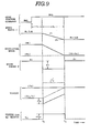
- the retard ⁇ R is a retard angle large enough to suppress the occurrence of a varition T o ' in output torque T o of the automatic transmission 306 that would otherwise take place during the shift (see Fig. 9).
- the flag F 11 is set. This causes the computer to memorize that the speed ratio r has becomne lower than the first reference value ⁇ 1 and the actual shift operation has begun.
- the spark timing control signal S I is corrected at the step 346 such that it takes a value expressed as ⁇ F + e Re
- the spark timing ⁇ of the engine 1 is retarded from the ordinary spark timing ⁇ F by ⁇ R as illustrated in Fig. 9.
- the initiation of a shift in the automatic transmission 306 and the completion thereof can be recognized accurately by monitoring the speed ratio, and the engine output is dropped by retarding the spark timing of the engine 301 during the transient period from the initiation of the shift to the completion thereof, preventing the occurrence of shocks during the shift. Since the engine output control mentioned above is rendered to occur always in timed with the initiation of the shift owing to a feedback control by monitoring the speed ratio r, the occurrence of shocks is alleviated to a sufficiently low level without any secondary shocks.
- a third embodiment is described. This embodiment is similar to the second embodiment except that, instead of the spark timing 9, the opening degree cP of a throttle valve is controlled during a shift to achieve a drop in the engine output.
- Fig. 10 is a flow chart showing a series of operations executed by a control unit 316 shown in Fig. 11.
- Fig. 11 is similar to Fig. 6 except the provision of a throttle valve 335 and a throttle valve actuator 336.
- the control unit 316 which is specifically shown in Fig. 12 is similar to Fig. 7 except the provision of a drive circuit 357 for the throttle valve actuator 336.
- the content of the control is different from that of the 'second embodiment only in that the operations of the correction ⁇ R (the retard) of the spark timing, of the ordinary spark timing ⁇ F , and of the spark timing control signal S I have been replaced with the operations of a correction ⁇ of the throttle opening degree, of a throttle opening degree ⁇ A and of a throttle opening degree signal S TH , respectively, (see steps 361, 362, 363, 364, and 365).
- FIG. 14 there is a flow chart illustrating the content of operations carried out in a fourth embodiment according to the invention.
- the construction of this embodiment is substantially the same as the second embodiment (see Figs. 6 and 7).
- the flow chart of this embodiment is different from that of the second embodiment (see Fig. 8) only in the provision of new steps 371, 372 and 37.
- a timer T l is started so as to measure time T 1 beginning with the instant t 1 (see Fig. 15).
- This embodiment operates in the same manner as the second embodiment under the normal condition where decisions that the speed ratio r drops below the first reference value ⁇ 1 and then it drops below the second reference value ⁇ 2 are made normally.
- the decision that r is lower than or equal to ⁇ 2 fails to be made, i.e., the completion of the shift fails to be recognized, the operation of the engine with the spark timing 9 retarded continue even after the instant t 31 thus allowing the engine to continue to produce the engine output Te of the decreased level.
- the reatard control of the spark timing is mandatory terminated when the time T 1 measured exceeds the above mentioned reference time value Ts thereby to prevent the occurrence of undesirable event.
- FIG. 16 there is a flow chart illustrating the content of operations carried out by a fifth embodiment according to the invention.
- the other construction is the same as the above mentioned fourth embodiment.
- control is substantially the same as that shown by the flow chart in Fig. 14 except the provision of steps 380 to 385.
- the operation of decreasing the retard ⁇ R by the predetermined value ⁇ (alpha) is repeated until r becomes less than or equal to ⁇ 2 or ⁇ R becomes less than or equal to zero.
- ⁇ 2 or 6 R becomes less than or equal to zero
- the spark timing is allowed to return to ordinary spark timing ⁇ F .
- a 2-3 upshift command occurs, and then at the instant t 2 when r becomes less than or equal to ⁇ 2 , the retardation of the spark timing 9 starts.
- the spark timing starts to increase gradually, and returns to the ordinary spark timing e F at the instant t 3 when r becomes less than or equal to ⁇ 2 .
- ⁇ (alpha) that was constant may be given a value variable with the value of the speed ratio r, and in this case, the step 355 may be skipped if the value of ⁇ (alpha) is varied so that the retard ⁇ R becomes equal to zero upon completion of the actual shift.
- the second to fifth embodiments have to be modified such that the decisions to be made are whether the speed ratio r has exceeded the respective reference values, and the engine output has to be increased during a shift.
- a lock-up type automatic transmission 306 has an input shaft, not shown, drivingly connected to an engine, also not shown via a lock-up type torque converter 405. It automatically selects one gear position out of first to fourth gear postions in accordance with running state of a vehicle by the action of a 1-2 shift valve 313, a 2-3 shift valve 314 and a 3-4 shift valve 315 provided in a hydraulic control system 307.
- a control unit 316 is a microcomputer based system that includes a CPU 324, a RAM 325, a ROM 326, an input/output interfeace circuit 427, a wave shaper 329, and an A/D converter 330.
- Input signals include an input shaft revolution speed signal S Ni from an input shaft revolution speed sensor 333, an output shaft revolution speed signal S N o from an output shaft revolution speed sensor 334, a 1-2 shift signal S 12 from a 1-2 shift switch 318, a 2-3 shift signal S 23 from a 2-3 shift switch 319, a 3-4 shift signal S 34 from a 3-4 shift switch 320, and an accelerator position signal S AC from an accelerator sensor 317, while output signals include a lock-up control signal S LU to be supplied to a lock-up solenoid 422.
- the sensors 333, 334, 317 and shift switches 318, 319, and 320 are substantially the same as their counterparts shown in Fig. 7.
- FIG. 21 there is a flow chart illustrating a series of operation carried out by the above mentioned control unit 316.
- an arithmetic operation is carried out to determine a lock-up control data T(n).
- the integer n used above designates the number of repetition of run of the routine shown in Fig. 21.
- Step 444 What is done at the step 444 is to determine based on the shift signal S 12 or S 23 or S 34 whether there occurred any change in gear position command. If the result of the decision at this step 444 is YES, the lock-up control which will be described hereinafter will be carried out.
- the content of the above mentioned change i.e., the content of the shift demand
- the content of the shift recognized is an upshift from the second to the third.
- an appropriate one for the content of the shift recognized at the step 445 is set.
- references 2-3 shift a value that is near but smaller than the speed ratio of 1.5 that is peculiar to the second gear position is set as the first reference C 1
- a value that is substantially equal to the speed ratio of 1.0 that is peculiar to the third gear position is set as the second reference C 2 .
- a decision is made whether the content of a memory register M that stores the lock-up control data T(n-1) obtained in the preceding run is equal to 1.
- a decision is made whether the speed ratio r is lower than or equal to the first reference C l .
- the speed ratio r is kept at the speed ratio of 1.5 that is peculiar to the second gear position during the response delay ⁇ T 1 and thus the relationship that r is greater than C 1 is maintained, so that the decision at the step 453 results in NO.
- step 459 is executed where a decision is made whether the speed ratio r has become equal to or lower than the second reference C 2 . As long as the speed ratio r stays greater than C 2 , the execution of the steps 441, 442, 451, 458, 459, and 463 is repeated, thus leaving the lock-up released.
- the flag F is reset as 00 which indicates the completion of the lock-up release during the shift.
- the initiation timing of the lock-up release is isalways brought into agreement with the instant t3 when the actual shift is initiated, thus preventing the occurrence of engine racing which was experienced in the conventional example as illustrated in Fig. 25.
Abstract
Description
- The present invention relates to a device for controlling a shift in gear position in an automatic transmission of a motor vehicle.
- Commonly, an automatic transmission has a plurality of gear positions, each providing a speed ratio peculiar to the particular gear positions, between a transmission input shaft and a transmission output shaft. Under the control of a control system, a command for one of the plurality of gear positions is made and the one gear position is established so as to produce an output torque sufficiently large enough to keep a motor vehile installed with the automatic transmission running. If there is a change in the running state of the motor vehicle, a change in gear position command, i.e., a shift comamnd, takes place in the control system. After a delay (i.e., a response delay) after an instant when the change in command has took place, a plurality of friction elements are put into action to initiate a shift. There is another delay (i.e., a shift delay) after the initiation of the shift until the completion thereof. During this transient period when the shift is being effected, a ratio of the revolution speed of the input shaft to that of the output shaft undergoes a change from a speed ratio peculiar to the old gear position to a speed ratio peculiar to a new gear position. If this change during this transient period is not smooth. substantial shocks are generated. However, since the shift is controlled in an open loop manner, it is next to impossible to make the speed ratio to always change in a predetermined schedule tailored to the shift. Thus, it is desired to control this shift in a closed loop manner (i.e., feedback control of the shift). In order to realize this feedback control, an excellent detector for detecting or measuring a speed ratio of the revolution speed of the input shaft to that of the output shaft is needed.
- Referring to a motor vehicle installed with an automatic transmission having an input shaft drivingly connected to an engine via a torque converter, a discussion will proceed hereinafter why substantial shocks are produced during a shift from a low gear position to a high gear position with an engine accelerator pedal kept depressed. One typical example is illustrated in Fig. 18 where there occurred at the instant tl a change in command from a second gear position to a third gear position. Referring to Fig. 18, at the subsequent instant t2 after a response delay ΔT1 from the instant tl, friction elements are put into action to initiate a shift, and the action of the friction elements is terminated to complete the shift at the subsequent instant t3 after a shift delay ΔT2 from the instant t2. The speed ratio is subject to a change from a speed ratio RL (1.4, for example) peculiar to the second gear position to a speed ratio Ra (1.0, for example) peculiar to a third gear position as illustrated by a fully drawn line during the time interval ΔT2 where the action of the friction elements progresses. The revolution speed of the transmission input shaft, i.e., an input shaft revolution speed Ni, also decreases in response to the change in the speed ratio during this time interval ÅT2 beginning with t2 and ending with t3 until it becomes equal to the revolution speed of the transmission output shaft, i.e., an output shaft revolution speed No. With the same opening degree of an engine throttle, an input torque Ti fed to the automatic transmission, which is generally equal in amount to an output torque of the engine Te, varies in inverse proportion to the above mentioned variation of the input shaft revolution speed Ni during the time interval L1T2. Theoretically, since it results from multiplying the input torque Ti with the speed ratio, an output torque To of the transmission stays substantially unchanged during the shift. However, the inertia of the engine works to resist the tendency of the input shaft decreasing its speed during this time interval ΔT2, applying a torque Tm due to inertia to the transmission input shaft, causing an increase as shown by To' in the transmission output torque To during the shift, causing generation of substantial shocks.
- Japanese patent application laid-open No. 58-207556 discloses a device for alleviating substantial shocks during a shift by causing a drop, in the engine output, from the normal level during the shift so as to suppress the above mentioned increase in the transmission output shaft. More particularly, according to this known device, the amount of delay in spark timing is increased during the shift so as to cause a drop in the engine output torque, thus suppressing the increase in the transmission output shaft. The initiation and termination of the above mentioned spark timing are brought into agreement with the initiation and termination of each shift in gear position taking place in the automatic transmission under the control of a timer circuit.
- Japanese patent application laid-open No. 58-77138 discloses a method of alleviating shocks taking place during a shift in an automatic transmission. According to this known method, the output torque of an engine is subject to a temporal variation (i.e., a temporal drop/increase) during a shift. The temporal variation in the engine output torque is initiated at a predetermined timing with the instant when a change in command for gear position takes place.
- Referring to a motor vehicle installed with a so-called lock-up type automatic transmission having an input shaft drivingly connected to an engine via a lock-up torque converter, i.e., a torque converter with a lock-up clutch, a discussion will proceed hereinafter how the lock-up clutch is released during a shift so as to alleviate shocks which would otherwise take place should the lock-up clutch be kept engaged during the shift.
- Japanese patent application laid-open No. 56-127856 which has a U.S. counterpart, now U.S. Patent No. 4,431,095 issued to Suga on Feb. 14, 1984 discloses a device for controlling a shift in a lock-up type automatic transmission. The operation of this known device is illustrated in Fig. 25 wherein a change in command from a second gear position to a third gear position occurred at the instant tl. Describing the operation of this known device referring to Fig. 25, a lock-up signal is subject to a change from ON level to OFF level at the subsequent instant t2 after a delay ΔT1 from the instant tl. The OFF level of the lock-up signal causes the lock-up torque converter to assume its converter state after releasing its lock-up clutch. The OFF level of the lock-up signal is maintained during a time interval ΔT2 beginning with the instant t2. After this time interval ΔT2, the lock-up signal resumes ON level. In response to this temporal stay of the lock-up signal in OFF level, the lock-up torque converter starts effecting a shift from lock-up state to converter state immediately after the instant t2, but it does not resume lock-up state immediately after the change in the lock-up signal from OFF level to OFF level. The resumption to lock-up state is considerably delayed and starts at the instant t5 as illustrated. This characteristic is attributed to the construction of a lock-up control hydraulic circuit. At the subsequent instant t3 after a response delay ΔT3 from the instant t1, friction elements are put into action to initiate a shift in gear position, and the shift is completed at the instant t4 after a shift delay ΔT4. The speed ratio changes from a speed ratio R2 peculiar to the second gear position down to a speed ratio R3 peculiar to the third gear position. Since the response delay ΔT3 is subject to a change owing to manufacturing variation from one producvt to another and/or oil temperature, the delay ΔT1 is set as being shorter than the response delay AT 3 so as to allow a variation in the response delay, thus leaving a time interval from the instant t2 to t3 where the lock-up torque converter works as a torque converter even though the shift is not yet initiated. During this time interval from t2 to t3' the engine speed NE sharply increases upto a level NE1 that is considerably higher than a level NE2 which the engine speed would reach if the time interval from t2 to t3 were substantially zero (t2 = t3). Considering a torque due to inertia that result from multiplying the inertia of the engine with the engine speed, the torque due to inertia increases considerably during a time interval from the instant t3 to t4, i.e., during the shift, causing substantial shocks to take place.
- From the preceding description, it will be recognized that the known devices are not satisfactory in alleviating shocks during a shift because they control the automatic transmission in an open loop manner during the shift.
- The present invention aims at controlling a shift in an automatic transmission in a closed loop manner in order to alleviate shocks which would occur during the shift in an automatic transmission.
- The present invention aims also at detecting or measuring an actual value in a speed ratio of a revolution speed of a transmission input shaft to that of a transmission output shaft during a shift in gear position in a transmission.
- Japanese patent application laid-open No. 57-120752 discloses a method of detecting a gear position established in a motor vehicle installed with a transmission. According to this known method, a pulse train signal generated by a rotational angle sensor of a distributor, and a pulse train signal generated by a vehicle speed sensor for a speed meter are used. The pulse train signal of the rotational angle sensor has a frequency variable in proportion to the revolution speed of a transmission input shaft, and the pulse train signal has a frequency variable in proportion to the revolution speed of a transmission output shaft. These pulse train signals are processed to find the revolution speed of the transmission input shaft and that of the transmission output shaft, and then the former is divided by the latter to give a speed ratio of input to output. In finding the revolution speed of each of the shafts, pulses generated during a unit length of time are counted and the result is generated as the revolution speed. In order to detect the revolution speed with a good accuracy, the unit length of time has to be sufficiently long. Besides, since the number of pulses counted during the unit length of time are considerably small at low vehicle speed, the precision drops considerably. Thus, this known method is not suitable for detecting an actual value in the speed ratio during a shift in gear position in a transmission.
- According to the present invention, there is provided a device for controlling a motor vehicle installed with an engine and an automatic transmission during a shift in gear position in the automatic transmission, the automatic transmission having an input shaft drivingly connected to the engine and an output shaft. The device comprises means for detecting an actual value in a speed ratio of the revolution speed of the input shaft to that of the output shaft during a transient period involving a shift in gear position taking place in the automatic transmission and generating an actual speed ratio indicative signal; and means for effecting a closed loop control based on said actual speed ratio indicative signal during the transient period.
- According to the present invention, there is provided a detector for detecting a speed ratio of an input shaft to an output shaft. The detector comprises:
- first sensor means for generating a first pulse train signal having a frequency variable in proportion to a revolution speed of the input shaft;
- second sensor means for generating a second pulse train signal having a frequency variable in proportion to a revolution speed of the output shaft;
- means for finding a first period of said first pulse train signal and generating a first period indicative signal indicative of said first period found;
- means for finding a second period of said second pulse train signal and generating a second period indicative signal indicative of said second period found; and
- means for calculating a ratio of said first period indicative signal to said second period indicative signal and generating said ratio as a speed ratio established in the transmission.
-
- Fig. 1 is a block diagram showing an automatic transmission for a motor vehicle incorporating a first embodiment according to the present invention;
- Fig. 2 is a diagrammatic sectional view showing a pressure regulator;
- Figs. 3(a), 3(b) and 3(b) are timing diagrams;
- Fig. 4 is a flow chart of the first embodiment;
- Fig. 5 is a graph illustrating a variation in speed ratio and a variation in duty ratio versus time during a shift;
- Fig. 6 is a block diagram of a power train for a motor vehicle incorporating a second embodiment according to the present invention;
- Fig. 7 is a block diagram of a control unit;
- Fig. 8 is a flow chart;
- Fig. 9 is a timing diagram showing the characteristic of operation of the second embodiment;
- Fig. 10 is a flow chart illustrating the operational characteristic of a third embodiment;
- Fig. 11 is similar view to Fig. 6 showing the third embodiment;
- Fig. 12 is a similar view to Fig. 7 showing the third embodiment;
- Fig. 13 is a timing diagram;
- Fig. 14 is a flow chart illustrating the operational characteristic of a fourth embodiment;
- Fig. 15 is a timing diagram;
- Fig. 16 is a flow chart illustrating the operational characteristic of a fifth embodiment;
- Fig. 17 is a timing diagram;
- Fig. 18 is a timing diagram used in discussing the prior art;
- Fig. 19 is a similar view to Fig. 6 showing a sixth embodiment;
- Fig. 20 is a block diagram of a control unit;
- Fig. 21 is a flow chart;
- Fig. 22 is a timing diagram;
- Fig. 23 is a timing diagram;
- Fig. 24 is a timing diagram; and
- Fig. 25 is a timing diagram used in discussing the prior art.
- Referring to Figs. 1 to 5, one embodiment according to the present invention is described.
- Referring to Fig. 1, there is schematically shown an
automatic transmission 1 installed in a motor vehicle having an engine, not shown. The automatic transmission has aninput shaft 11 drivingly connected via a torque converter to the engine in a known manner, an output shaft drivingly connected with driving wheels, not shown, of the motor vehicle in a known manner, and a change-speed mechanism which is shiftable to three forward gear positions and one reverse gear position. The change-speed mechanism comprises two groups of planetary gear sets 17, 18, and a plurality of friction elements that include a front clutch 12, a rear clutch 13, aband brake 14, a low andreverse brake 15, and a one-way clutch 16. - Among all, the friction elements 12-15 are selectively put into action (engaged/released), thus changing a speed ratio of the revolution speed of the
input shaft 11 to that of theoutput shaft 11. The friction elements 12-15 are engaged or released in each of drive ranges as shown in Table.

- The friction elements 12-15 are actuated by hydraulic pressure pistons 42-45, respectively, such that each of the friction elements is engaged in response to hydraulic fluid pressure supplied to the corresponding hydraulic pressure piston.
- The hydraulic pressures supplied to the above mentioned hydraulic pressure pistons 42-45 are regulated by pressure regulator valves 46a-46d, respectively. These pressure regulator valves are of the same construction like the one as shown in FIg. 2, for example.
- Referring to Fig. 2, an
inlet passage 53 is supplied with a hydraulic fluid pressure PL having a predetermined constant value by a source of hydraulic fluid pressure (not shown). An output hydraulic fluid pressure PC produced after pressure regulation appears in anoutlet passage 51 to be supplied to the corresponding one of the hydraulic pressure piston. The hydraulic fluid pressure Pc variable in response to a bias pressure Ps that is variable in response to the drainage rate via adrain 54. - The drainage rate via the
drain 54 is variable in response to a bias force applied to aneedle valve 62, which bias force is adjustable by varying ON-OFF duty ratio of an energization current passing through asolenoid valve 61. That is, when thesolenoid valve 61 stays in OFF state (duty ratio DON = 0), thedrain 54 is fully opened, allowing the pressure Ps to drop to its lowest level, thus allowing aspool 56 to assume a position illustrated by an upper half thereof in Fig. 2 wherein theoutflow port 51 is allowed to communicate with adrain 55. This causes allowing the output pressure PC to assume its lowest level. Under this condition, the corresponding friction element is released. - If duty ratio DON is increased the drainage rate is decreased in response to the duty ratio DON, thus causing the pressure Ps to increase. In this case, the
spool 56 assumes a position where the pressure in thechamber 50 balances with the pressure in afeedback chamber 52, thus causing the output pressure Pc to increase. - The solenoid valves for the
regulator valves control unit 30. Thecontrol unit 30 is a microcomputer system that comprises a CPU 31, amemory 32, an I/O interface 33 and asystem clock 34. - In order to detect or measure a speed ratio r of the revolution speed of the
input shaft 10 to that of theoutput shaft 11, a detector is provided which includes thecontrol unit 30. It also includes an input shaftrevolution speed sensor 21, an output shaftrevolution speed sensor 22,wave shpers cross detectors 25, 26, and period counters 28, 29. Thesensor 21 includes a magnetic pinion 21b attached to theinput shaft 10 and a magnetic pick-up 21a arranged adjacent to themagnetic pinion 21. According to this arrangement, the magnetic pick-up 21a generates a pulse train signal P1 having a frequency variable in proportion to the revolution speed of themagnetic pinion 21, i.e., the revolution speed of theinput shaft 10. - Similarly, the
sensor 22 includes amagnetic pinion 22b attached to theoutput shaft 11, and a magnetic pick-up 22a. The magnetic pick-up 22a generates a pulse train signal P2 having a frequency variable in proportion to the revolution speed of theoutput shaft 11. - One pulse of each of the above mentioned pulse train signal P1 and P2 is generated whenever each of the teeth of the corresponding one of the
magnetic wheels 21b and 22b passes the corresponding one of the magnetic pick-ups wave shapers corss detectors 25 and 26, a zero cross point Z (n = the integer) of each of said square-shaped pulses is detected, thus casusing the generation of a trigger pulse Pn (n = the integer) as shown in Fig. 3(c). Each of the period counters 28 and 29 is provided with a counter that counts the output of aclock 34 mounted within thecontrol unit 30. Whenever it receives a trigger pulse P , the content of the counter generated as its output to an output register to be stored therein and the counter is reset. Thus, the content of the output register corresponds to the length of time, i.e., a time interval, between the adjacent two trigger pulses Pn and Pn+l and this length of time T1 or T2 corresponds to the period of the corresponding pulse train signal P1 or P2. Hereinafter, the reference character T1 is used to denote the period of the pulse train signal P1, and the reference character T2 is used to denote the period of the pulse train signal P2. - Fig. 4 is a flow chart showing the sequence of operations executed in the above mentioned
control unit 30. - The series of operations shown in Fig. 5 relates to a control of the
band brake 14 of theautomatic transmission 1. Although not shown, similar flow charts for the front clutch, rear clutch, and low & reverse brake are stored. These four flow charts are executed consequtively and the execution of each of them is initiated after a predetermined length of time. The series of operations for the band brake is controlling as shown in Fig. 5 is executed after a length of time of T. - First of all, a
step 201 is executed where a decision is made of which running range should be selected. This decision making atstep 201 involves selecting one running range out of [N, P], [R], [D1], [D2], [D3] based on parameters detected such as, a vehicle speed, a position of a shift lever, and an opening degree of a throttle valve. The operation atstep 201 also involves comparing a new running range determined in the present run with an old running range determined in the preceding run, and deciding whether [D1] range determined in the preceding run has changed to [D2] range determined in the present run, i.e., whether a shift from the first to the second gear position (hereinafter abbeviated as a 1-2 shift) is demanded. - When the decision made at the
step 201 ends in 1-2 shift, theband brake 14 has to be engaged or applied because the application of theband brake 14 takes place only during a shift from [D1] range to [D2] range, as illustrated in the Table mentioned before. - When the decision made at the
step 201 turns out to be an instruction that 1 - 2 shift is to be initiated speed ratio r is given atsteps band brake 14 is determined atsteps 204 to 211. - At the
step 202, the period T1 of the pulse train signal P1 stored in the output register within the period counter 28 and the period T2 of the pulse train signal P2 stored in the output register within the period counter 29 are read. - Then, at the
step 203, the ratio (T2/Tl) of the above mentioned period T2 to the period T1 is calculated. Since this ratio is equal to the speed ratio of the revolution speed of theinput shaft 10 to that of theoutput shaft 11, r = T2/T1 is set. - At the
subsequent step 204, the time t is updated by adding to the old time tn-1 given in the preceding run an increase At deemed to be required for the operations from thestep 202 to step 211. - At
step 205, a target value in speed ratio r0(tn) for the instant tn is read at thememory 32. The setting at thememory 32 is such that the target value varies as shown by a one-dot chain line curve in Fig. 5 which has been so chosen as to alleviate shocks which takes place during a 1-2 shift. What is intended is to control hydraulic fluid pressure with which theband brake 14 is applied in such a manner as to bring an actual value in speed ratio r into agreement with the target value r0. - At
step 206, the actual value r is compared with the target value r0. When r is greater than r0, astep 208 is executed where a predetermined increase +d is placed as a duty ratio variation ΔD. This duty ratio variation AD represents a variation in duty ratio DON of the excitation current Sc supplied to the solenoid valve of thepressure regulator valve 46c forming the hydraulic pressure circuit for theband brake 14. - When r is equal to r0, a
step 207 is executed where 0 (zero) is placed as ΔD, while when r is less than r0, astep 209 is executed when a decrease -d is placed as ΔD. - At a
step 210, the duty ratio variation ΔD is added to an old duty ratio DON(n-1) that was obtained in the preceding run and the result in placed as a new duty ratio DON(n). Thereafter, the above mentioned new duty ratio DON is set as the duty ratio of the excitation current passing through thesolenoid valve 61 of thepressure regulator valve 46c. - At a
step 211, the time tn beginning with the instant when 1-2 shift was commanded is compared with a predetermined period TN to determine whether the time tn has reached TN. Thus, the series of operations begining withstep 202 and ending withstep 211 is repeated until tn exceeds TN. - When, on the other hand, the decision making at the
step 201 ends in [N, P], [D1], [D3] or [R], DON = 0 is set as the duty ratio of the excitation current Sc because, as apparent from the Table 1, theband brake 14 is to released. - When the running range to be selected is found to be [D2], DON = D2 is set as the duty ratio of the excitation current Sc. D2 is a predetermined value large enough to render the
band brake 14 fully applied. - Fig. 5 is a graph showing a variation in the speed ratio r versus time during a 1-2 shift and also a variation in the duty ratio DON of the excitation current Sc. The variation in the duty ratio DON represents in hydraulic fluid pressure PC supplied to the hydraulic
fluid pressure piston 44 during the 1-2 shift. - Referring to Fig. 5, since [D1] range is established prior to the instant tl, the duty ratio DON is equal to O, (step 221) and thus the
band brake 14 is released. Under this condition, the speed ratio is equal to a value (for example, 2.8) peculiar to this [D1] range. - At the instant t1 when a 1-2 shift is demanded after the vehicle speed has increased sufficiently high enough for this shift, the series of operations from the
step 202 to step 211 (see Fig. 5) is executed where the comparison of r with r0 is repeated after every predetermined length of time t so as to increase or decrease the duty ratio DON. As a result, the actual speed ratio value r follows closely the target value r0. - After the predetermined period TN beginning with the instant tl, the predetermined value D2 is set as the duty ratio DON (step 231), resulting in the complete application of the
band brake 14. Thereafter, the vehicle travels at the speed ratio value (for example, 1.4) peculiar to the [D2] range. - As explained in the preceding description, according to this embodiment, since the setting is made such that the target value r0 gradually decreases during the predetermined period TN until it becomes equal to the new speed ratio, the actual rotational speed ratio r is adjusted so as to closely follow this target value r0, thus causing a smooth shift to be made without any abrupt application of the
band brake 14 which would result in the occurrence of substantial shocks. - Since the periods T1 and T2 of the pulse train signals P1 and P2 produced by the input shaft
revolution speed sensor 21 and the outout shaftrevolution speed sensor 22 are used, the actual speed ratio r can be detected at the instant whenever every two pulses of each of the pulse train signals P1 and P2 have been generated. As a result, it can be detected within a short length of time. - This, therefore, has realized a feedback control with excellent precision as shown by the flow chart shown in Fig. 4 where the actual speed ratio value r is brought into agreement with the target value r0.
- Although, in the above mentioned embodiment, the input shaft
revolution speed sensor 21 and the output shaftrevolution speed sensor 22 are mounted directly to theinput shaft 10 and theoutput shaft 11, respectively, sensors of the type which indirectly detect the revolution speed may be used as long as they generate a pulse train signal with a frequency variable with the rotational speed of the input shaft and the output shaft. For example, the sensors may be mounted to the planetary gear sets 18 and 19 or a rotational angle sensor and a vehicle speed sensor for a speed meter may be used as such sensors. - As different from the manner of varying the duty ratio DON of each of the excitation currents Sa to Sd supplied to the seolenoid valves by a predetermined amount | d |, the variation may be altered in response to the speed ratio or the engine load. In this case, the variation | d | mey be altered in response to the speed ratio or the engine load directly or the variation | d | that is constant may be multiplied with a coefficient variable with the speed ratio or the engine load.
- The variation characteristic of the target value r0 is not limited to that illustrated in Fig. 5 and may be set as desired as long as it is effective in decreasing shift shocks.
- Referring to Figs. 6 to 9, a second embodiment is described hereinafter.
- Referring to Fig. 6, there are illustrated an
engine 301, and anautomatic transmission 306 drivingly connected via atorque converter 306a to theengine 301. - The
engine 301 hasspark plugs 309 provided for its cylinders, respectively, and is provided with adistributor 310. Thedistributor 310 applies a secondary high voltage that has been generated by continuous supply of a primary electric current to the spark plugs 9, selectively, at a timing determined by aspark timing controller 311 under the control of a spark timing control signal SI. Theengine 301 increases its output as anaccelerator pedal 312 is depressed deeply because the flow rate of intake air increases in response to the depression of theaccelerator pedal 312 and the amount of fuel injection by an injector (not illustrated) also increases in response to the depression of theaccelerator pedal 312. This engine output is fed to theautomatic transmission 306 via thetorque converter 306a. - Owing to a 1-2
shift valve 318, a 2-3shift valve 314 and a 3-4shift valve 315 within a hydraulicpressure control system 307, theautomatic transmission 306 automatically selects a gear position out of four gear positions which is suitable for a running condition of the vehicle. - A
control unit 316, as shown in Fig. 7, is a microcomputer based system which is provided with aCPU 324, aRAM 325, aROM 326, aninput interface circuit 327, anoutut interface circuit 328, awave shaper 329, an A/D converter 330, and adrive circuit 331. - Input signals fed to the
control unit 316 comprises an input shaft revolution speed signal SNi of an input shaft revolution speed sensor 33, an output shaft revolution speed signal SNo of an output shaftrevolution speed sensor 334, a crank angle signal Sc of acrank angle sensor 321, an engine speed signal SNc of anengine speed sensor 323, a 1-2 shift signal S12 of a 1-2shift switch 318, a 2-3 shift signal S23 of a 2-3shift switch 319, a 3-4 shift signal S34 of a 3-4shift switch 320, an accelerator depression signal SAC from anaccelerator sensor 317, an intake flow signal SQ from anair flow meter 303, and a coolant temperature signal ST from an enginecoolant temperature sensor 322. Output signals from thecontrol unit 316 comprise a spark timing control signal SI to be fed to thespark timing controller 311. - The above mentioned
revolution speed sensor 333 and the output shaftrevolution speed sensor 334 are similarly constructed and arranged to thesensors sensors wave shaper circuit 329. Thewave shaper 329 generates a short rectangular wave pulse in response to the rise of every one of pulses of the signals SNi and SNo fed thereto. The crank angle signal Sc and the engine speed signal SNe are subject to similar treatment at thewave shaper 329. - The
accelerator sensor 317 is constructed of a potentio meter which generates an analog signal variable in proportion to the depression degree (acceleration degree) of theaccelerator pedal 312. The accelerator signal SAC from thisaccelerator sensor 317, an intake air amount signal SQ from theair flow meter 303 and the coolant temperature signal ST from the enginecoolant temperature sensor 322 are converted to digital signals at the A/D converter 330. - The 1-2
shift switch 318 and 2-3shift switch 319 are like their counterparts described, for example, in U.S. patent No. 4,431,095. They are closed and generate low level signals when spools of the 1-2shift valve 313 and 2-3shift valve 314 assume downshift positions, respectively, while they are opened and generate high level signals when the spools assume upshift positions, respectively. A 3-4shift switch 320 is constructed similarly and closed to generate a low level signal when a spool of the 3-4shift valve 315 assumes a downshift position but opened to generate a high level signal when the spool assumes an upshift position. Thus, the shift signals S 12' S 23 and S 34 are expressed by various combinations of high and low level signals as shown in the following Table.
- In the Table, the reference character H represents a high level signal and the reference character L a low level signal.
- Fig. 8 is a flow chart showing a sequence of operations executed by the above mentioned
control unit 316. - The series of operations illustrated in Fig. 8 is started by turning ON an ignition switch and the execution thereof is repeated after a length of time AT.
- First of all, at a
step 341, a shift position signal S12 or S23 or S34 coming out of the 1-2shift switch 318, 2-3shift switch 319 and 3-4shift switch 320 is read, and at astep 342, a decision is made whether any change in gear position signal occurred. - If, now, no change in gear position signal took place, a flag F is reset as 00 at a
step 343, and then a retard θR is set as 0. - At a
step 345, an ordinary spark timing θF, i.e., an appropriate spark timing for non shifting state, is obtained by a table look-up of a data table of ordinary spark timing θF which is preset versus data including accelerator signal SAC, intake air flow signal SQ, and coolant temperature signal ST based on the accelerator signal SAC, the intake air flow signal SQ, and the coolant temperature signal ST which have been obtained in another routine (not illustrated). - At a
step 346, a spark timing control signal S to be fed to thespark timing controller 311 is given as a sum (θF + θR) of the ordinary spark timing θF and its correction, i.e., a retard θR. As a result, the spark timing of theengine 301 is adjusted to θF + θR. - Since, when the decision that no change in gear position signal is made, the retard θR = 0, the
spark timing 0 of theengine 301 is adjusted to the ordinary spark timing θF, thus permitting the engine to produce an appropriate output for running state of the vehicle. - If the decision made at the
step 342 turns out to be YES, i.e., a case where a change in gear position signal occurred, a determination is made based on gear position signals before and after the decision making at thestep 342 what kind of change in gear position has occurred, i.e., which shift command has occurredstep 347. That is, what is done at thestep 347 is to determine which one of 1-2 shift command, 2-3 shift command and 3-4 shift command has occurred. - At a
step 348, a first reference value β1 and a second reference value β2 which are preset for content of the shift command determined are obtained after reading the data in the memory. These reference values β1 and β2 are used to determine the instant when a shift is initiated and the instant when it is completed, and a different pair of values is set for every different shift command. - At a
step 349, the flag F = 01 is set. The fact that the flag F = 01 is set is memorized by the computer as the occurrence of a change in gear position signal. - Referring to Fig. 9, assuming now that the gear position signal has changed from the second to the third gear position (2-3 shift) at the instant t1, a decision is made that there has occurred a change in gear position command in the first run immediately after the instant tl and the
steps - At a
step 350, an input shaft revolution speed Ni is obtained from the output signal SNi of the input shaftrevolution speed sensor 333 and an output shaft revolution speed No is obtained from the output signal SNo of the output shaftrevolution speed sensor 334, and their ratio Ni/No is obtained and set as the actual speed ratio r. - More particularly, the actual speed ratio r is given by finding a period of a pulse train signal in a similar manner to the first embodiment.
- At a
step 351, a decision is made whether the content of the flag F is 01 or 11. Since, now, the content of the flag is 01, astep 352 is executed where the speed ratio r is compared with the first reference value β1. In the case as illustrated in Fig. 9, for example, the speed ratio changes from RL(1.4) to RH(1.0) during a 2-3 shift, the setting of the first reference value β1 is such that it is less than and very near RL. On the other hand, the second reference value β2 is given RH. - Referring to Fig. 9, during the response delay ΔT1, the speed ratio r continues to stay at RL, causing the decision made at the
step 352 to end in NO. Under this condition, the spark timing is kept at the ordinary spark timing θF owing to the operations at thesteps - Hereinafter, the series of operations through the
steps 341 to 343, 350 to 352, 345, 346 is executed repeatedly until r becomes equal to or less than β1. When r becomes equal to or less than β1, the decision made at thestep 352 results in YES, allowing the execution of astep 353 wherein the retard θR is determined by computation. Possible manners of such computation include giving the retard θR by performing arithmetic operatin based on the content of the shift command and the ordinary spark timing θF, and giving the retard θR by table look-up of a preset data table. The retard θR is a retard angle large enough to suppress the occurrence of a varition To' in output torque To of theautomatic transmission 306 that would otherwise take place during the shift (see Fig. 9). - At the
next step 354, the flag F = 11 is set. This causes the computer to memorize that the speed ratio r has becomne lower than the first reference value β1 and the actual shift operation has begun. - Since the retard θR has been set by computation in the above mentioned manner, the spark timing control signal SI is corrected at the
step 346 such that it takes a value expressed as θF + eRe As a result, the spark timing θ of theengine 1 is retarded from the ordinary spark timing θF by θR as illustrated in Fig. 9. - This causes the engine output Te to drop, causing the input torque Ti to drop by ΔTi. This drop works to offset the variation ATm in the torque Tm owing to the inertia which variation is caused by the shift operation. As a result, shocks are alleviated.
- The above mentioned retard action of the spark timing continues until the speed ratio r becomes lower or equal to the second reference value β2. This series of operations is maintained because the decision made at the
step 351 always results in 11 and the decision made at thestep 355 alway results in NO until r becomes lower or equal to β2. - When the shift in the
automatic transmission 306 is completed (at the instant t3), the speed ratio r becomes equal to the second reference value β2. This cause the decision made at thestep 355 to turn out to be YES, allowing the execution ofsteps - As described above, according to this embodiment, the initiation of a shift in the
automatic transmission 306 and the completion thereof can be recognized accurately by monitoring the speed ratio, and the engine output is dropped by retarding the spark timing of theengine 301 during the transient period from the initiation of the shift to the completion thereof, preventing the occurrence of shocks during the shift. Since the engine output control mentioned above is rendered to occur always in timed with the initiation of the shift owing to a feedback control by monitoring the speed ratio r, the occurrence of shocks is alleviated to a sufficiently low level without any secondary shocks. - Referring to Figs. 10 to 13, a third embodiment is described. This embodiment is similar to the second embodiment except that, instead of the spark timing 9, the opening degree cP of a throttle valve is controlled during a shift to achieve a drop in the engine output. Fig. 10 is a flow chart showing a series of operations executed by a
control unit 316 shown in Fig. 11. Fig. 11 is similar to Fig. 6 except the provision of athrottle valve 335 and athrottle valve actuator 336. Thecontrol unit 316 which is specifically shown in Fig. 12 is similar to Fig. 7 except the provision of adrive circuit 357 for thethrottle valve actuator 336. - Referring specifically to the flow chart shown in Fig. 10, the content of the control is different from that of the 'second embodiment only in that the operations of the correction θR (the retard) of the spark timing, of the ordinary spark timing θF, and of the spark timing control signal SI have been replaced with the operations of a correction Δϕ of the throttle opening degree, of a throttle opening degree ϕA and of a throttle opening degree signal STH, respectively, (see
steps - The operation of this third embodiment will be readily understood from Fig. 13.
- Referring next to Fig. 14, there is a flow chart illustrating the content of operations carried out in a fourth embodiment according to the invention. The construction of this embodiment is substantially the same as the second embodiment (see Figs. 6 and 7).
- The flow chart of this embodiment is different from that of the second embodiment (see Fig. 8) only in the provision of
new steps - At the
step 371, a timer Tl is started so as to measure time T1 beginning with the instant t1 (see Fig. 15). - At the
step 372, a decision is made whether the time T1 measured is equal to or greater than a reference time value Ts. If T1 is equal to or greater than Ts, thestep 373 is executed where the flag F is reset, the timer T1 is cleared, and the retard θR in sprak timing is set as 0 (zero). As shown in Fig. 15, the reference time value Ts must be sufficiently long enough to cover a length of time beginning with the instant t1 when there is a change in gear position command and ending with the instant t3 when shift in theautomatic transmission 306 is completed. - This embodiment operates in the same manner as the second embodiment under the normal condition where decisions that the speed ratio r drops below the first reference value β1 and then it drops below the second reference value β2 are made normally.
- If abnormal condition occurs where owing to a malfunction due to an error in signal system or noise, the decision that r is lower than or equal to β2 fails to be made, i.e., the completion of the shift fails to be recognized, the operation of the engine with the spark timing 9 retarded continue even after the instant t31 thus allowing the engine to continue to produce the engine output Te of the decreased level. In order to provide a safeguard against the occurrence of this event, the reatard control of the spark timing is mandatory terminated when the time T1 measured exceeds the above mentioned reference time value Ts thereby to prevent the occurrence of undesirable event.
- Referring to Fig. 16, there is a flow chart illustrating the content of operations carried out by a fifth embodiment according to the invention. The other construction is the same as the above mentioned fourth embodiment.
- The content of the control is substantially the same as that shown by the flow chart in Fig. 14 except the provision of
steps 380 to 385. - At the
step 380, a decision is made whether the content of the flag F is 01 or 10 or 11. If the flag F is equal to 11, the step 81 is executed where a decision is made whether the sign of a second derivative r of the speed ratio r is positve or negative. What is done at this step is to decide whether a first derivative r of the speed ratio r is on the incline or decline. If the second derivative r is less than or equal to zero, the flag F = 11 is maintained, thus leaving the spark timing θ subject to retard θR. If the second derivative r is greater than zero, thestep 382 is executed where the flag F = 10 is set, thus allowing the floowing run of this flow chart to select thestep 355 after thestep 380. At thestep 355, a decision is made whether r is less than or equal to β2. - If r is greater than β2, the step 383 is executed where the retard θR is decreased by a predetermined value α (alpha), and then the
step 384 is executed where a decision is made whether the result θR of operation at the step 383 is less than or equal to zero. If θR is less than or equal to zero, thestep 385 is executed where θR = 0 and F = 00 are set. - Thus, the operation of decreasing the retard θR by the predetermined value α (alpha) is repeated until r becomes less than or equal to β2 or θR becomes less than or equal to zero. When r becomes less than or equal to β2 or 6R becomes less than or equal to zero, the spark timing is allowed to return to ordinary spark timing θF.
- The operation just described is illustrated in Fig. 17. At the instant tl, a 2-3 upshift command occurs, and then at the instant t2 when r becomes less than or equal to β2, the retardation of the spark timing 9 starts. At the instant t2' when the rate at which the first derivative r of the speed ratio r decreases (the second derivative r becomes greater than zero), the spark timing starts to increase gradually, and returns to the ordinary spark timing eF at the instant t3 when r becomes less than or equal to β2.
- The advantage given by this control whereby the output torque of the engine varies smoothly near the instant when the actual shift operation is completed is that the occurrence of secondary shift shocks is alleviated, which secondary shift shocks would be occurred in the event where the variation To' in the output torque To of the automatic transmission during the shift decreases gradually at the instant t3 rather than it decreases abruptly, or where the amount of the drop ΔTi in the engine output is less than that of the torque variation ΔTm due to the inertia.
- As will be readily understood from the flow chart shown in Fig. 16, similarly to the flow chart shown in Fig. 14, the retarding of the spark timing is foribly terminated after a predetermined length of time Ts beginning with the instant tl.
- The above mentioned value α (alpha) that was constant may be given a value variable with the value of the speed ratio r, and in this case, the
step 355 may be skipped if the value of α (alpha) is varied so that the retard θR becomes equal to zero upon completion of the actual shift. - It goes without saying that in order to drop the engine output, the techniquue of decreasing the throttle opening degree ϕ which has been employed in the third embodiment shown in Figs. 10 to 13 may be applied to the fourth and fifth embodiments (see Figs. 14 and 16). The technique of controlling the engine output in response to the variation in the second derivative r of the speed ratio r which has been employed by the fifth embodiment (see Fig. 16) may be applied to the third embodiment (see Fig. 10).
- In each of the second to fifth embodiments described above, the engine output control for the purpose of decreasing the shift shocks occurring during an upshift has been described, similar control technique used in each of these embodiments may equally used in engine control for reducing shift shocks occurring during a downshift.
- When applying to conrolling shift shocks during a downshift, the second to fifth embodiments have to be modified such that the decisions to be made are whether the speed ratio r has exceeded the respective reference values, and the engine output has to be increased during a shift.
- In the preceding description, what are employed for controlling the engine output involve a techinque of retarding the spark timing 6 and a technique of decreasing the throttle opening ϕ. However, decreasing the fuel amount supplied to the engine, increasing the exhaust gas recirculation amount, throttling the intake air flow passage and decreasing the charging pressure of the turbo charger are another expedients which may be employed.
- Referring to Figs. 19 to 24, a sixth embodiment according to the present invention is described.
- Referring to Fig. 19, a lock-up type
automatic transmission 306 has an input shaft, not shown, drivingly connected to an engine, also not shown via a lock-uptype torque converter 405. It automatically selects one gear position out of first to fourth gear postions in accordance with running state of a vehicle by the action of a 1-2shift valve 313, a 2-3shift valve 314 and a 3-4shift valve 315 provided in ahydraulic control system 307. - As shown in Fig. 20, a
control unit 316 is a microcomputer based system that includes aCPU 324, aRAM 325, aROM 326, an input/output interfeace circuit 427, awave shaper 329, and an A/D converter 330. - Input signals include an input shaft revolution speed signal SNi from an input shaft
revolution speed sensor 333, an output shaft revolution speed signal S No from an output shaftrevolution speed sensor 334, a 1-2 shift signal S12 from a 1-2shift switch 318, a 2-3 shift signal S23 from a 2-3shift switch 319, a 3-4 shift signal S34 from a 3-4shift switch 320, and an accelerator position signal SAC from anaccelerator sensor 317, while output signals include a lock-up control signal SLU to be supplied to a lock-upsolenoid 422. Thesensors switches - Referring to Fig. 21, there is a flow chart illustrating a series of operation carried out by the above mentioned
control unit 316. - The series of operations illustrated in this Figure is initiated after the ignition switch is turned ON, and thereafter the execution of them is repeated after lapse of a predetermined length of time A.T.
- First of all, at a
step 441, an arithmetic operation is carried out to determine a lock-up control data T(n). The lock-up control data is obtained using a lock-up schedule (which is stored as a data Table) that is predetermined versus the gear position indicated by the shift signals S12, S23 and S34 and the position of the accelerator as indicated by the accelerator signal SAC. If it turns out that lock-up is to be effected, T(n) = 1 is set, while it turns out that lock-up is to be released, T(n) = 0 is set. The integer n used above designates the number of repetition of run of the routine shown in Fig. 21. - At a
step 442, a decision is made whether the content of a flag F is equal to 00. What is meant by the fact that the flag F is 00 is that neither shift nor lock-up is being carried out. If, under this condition, a change is gear position command is not detected as a result of operations atsteps step 450 is executed where the lock-up control data T(n) given at the above mentionedstep 441 is issued as a control signal SLU for the lock-up solenoid 22 (actually, there is provided a power circuit which turns ON or OFF the excitation current supplied to the lock-upsolenoid 422 in response to T(n)). Thus, if the control date T(n) is 1, the lock-upsolenoid 422 is turned ON, effecting the lock-up, whereas if the control data T(n) is equal to 0, the lock-upsolenoid 422 is turned OFF, releasing the lock-up. - What is done at the
step 444 is to determine based on the shift signal S12 or S23 or S34 whether there occurred any change in gear position command. If the result of the decision at thisstep 444 is YES, the lock-up control which will be described hereinafter will be carried out. - Hereinafter, in order to make the explnation in detail, a graph shown in Fig. 22 is also referred to.
- As an example, an upshift from the second gear position to the third gear position is descriubed. The same control procudure is applicable to the other shift operations.
- Prior to the instant t,, the second gear position is maintained and T(n) that has been given at the
step 441 is equal to 1. Thus, under this condition, the control signal SLU for the lock-upsolenoid 422 is equal to 1, thus allowing the lock-up to be effected. - When there occurs a change in gear position command from the second gear position to the third gear position at the instant tl, steps 445 and 446 of the flow chart shown in Fig. 21 are executed and then the flag F = 01 is set at a
step 447. At thestep 445, the content of the above mentioned change, i.e., the content of the shift demand, is recognized. In this example, the content of the shift recognized is an upshift from the second to the third. - At the
step 446, among different pairs of first and second references which are predetermined for various contents of shift, an appropriate one for the content of the shift recognized at thestep 445 is set. In this example, as references 2-3 shift, a value that is near but smaller than the speed ratio of 1.5 that is peculiar to the second gear position is set as the first reference C1, and a value that is substantially equal to the speed ratio of 1.0 that is peculiar to the third gear position is set as the second reference C2. At astep 448, a decision is made whether the content of a memory register M that stores the lock-up control data T(n-1) obtained in the preceding run is equal to 1. - Sinbce, in this example, T(n) was equal to 1 before the instant t,, M is equal to 1, allowing the execution of a
step 452 where an actual speed ratio r is obtained by a similar computation to that described in connection with thestep 350 in Fig. 8. - At a
step 453, a decision is made whether the speed ratio r is lower than or equal to the first reference Cl. Explaining here how the speed ratio varies after the instant t1, the speed ratio r is kept at the speed ratio of 1.5 that is peculiar to the second gear position during the response delay ΔT1 and thus the relationship that r is greater than C1 is maintained, so that the decision at thestep 453 results in NO. - Since the flag F = 01 is maintained until r becomes equal to or lower than C,, a series of operations at
steps - Thereafter, at the instant t3 after the response delay ΔT1, the actual shift operation in the automatic transmission 6 is initiated, causing the speed ratio r to decrease. Thus, immediately after the instant t3, the speed ratio r becomes below the .first reference C1, causing the decision at the
step 453 to result in YES. - As a result, a
step 454 is executed where the control signal SLU = 0 is set. This causes the lock-upsolenoid 422 to be turned into OFF state, thus releasing the lock-up. - At the
next step 455, a desicion is made whether the lock-up control data T(n) is equal to 1. If it is equal to 1, astep 456 is executed where the flag F = 10 is set, whereas if it is equal to 0, astep 457 is executed where the flag F is reset as being equal to 00. - It is assumed, in this example, that the lock-up is needed even during operation at the third gear position and thus T(n) = 1 is obtained at the computation at the
step 441. Thus, under this condition, after the execution of thestep 455, the flag F = 10 is set at thestep 456. - Thereafter, the
steps step 459 is executed where a decision is made whether the speed ratio r has become equal to or lower than the second reference C2. As long as the speed ratio r stays greater than C2, the execution of thesteps - When the speed ratio r become equal to or lower than C2, at the instant t4 when the shift in the
transmission 306 is completed, the decision at thestep 459 turns out to be YES, thus allowing the execution ofsteps solenoid 422 is set in accordance with the lock-up control data T(n). Since, now, the data T(n) is equal to 1, the control signal SLU = 1 is set, allowing the resumption to the lock-up. If T(n) is equal to 0, the control signal SLU for the lock-upsolenoid 22 is kept as being equal to the same state as thestate 0 set at thestep 454 in the preceding run, and the relationship T(n) = SLU = 0 is maintained, thus leaving the lock-up action released. - At a
step 462, the flag F is reset as 00 which indicates the completion of the lock-up release during the shift. - As a result of the operations described above, the initiation timing of the lock-up release is isalways brought into agreement with the instant t3 when the actual shift is initiated, thus preventing the occurrence of engine racing which was experienced in the conventional example as illustrated in Fig. 25.
- Besides, since the instant t4 when the shift is completed is detected and the lock-up release is terminated at this instant, the resumption to the lock-up action after the completion of the shift operation can be effected rapidly without any delay.
- Although, in the above description, a case where there occurs a shift from the second gear position with the lock-up to the third gear position with the lock-up has been explained, there is described as to a shift from the second gear position with the lock-up to the third gear position with the converter state (lock-up release state) referring to Fig. 23..
- Referring to Fig. 23, at the instant tl when a change in gear position command occurs, T(n) = 1 and M = 1 hold, and thus the execution of
steps step 453 turns out to be YES, and thus thesteps 454 and 455 (where the decision results in NO because T(n) = 0) are executed. and thestep 457 is executed where the flag F = 00 is set Thus, the lock-up is released. - Subsequently, the
steps 441 to 448 are executed. Since M = 0 is recognized at thestep 448, thestep 449 is executed where the flag F = 10 is set. - The lock-up release continues until the speed ratio r becomes equal to or lower than C2. When r = C2 is established (at the instant t4), the result of the decision at the
step 459 turns out to be YES. Then, at the next step 60, a decision is made whether T(n) is equal to 1. Since, now, T(n) = 0, the control signal SLU for the lock-upsolenoid 22 is kept at 0, thus allowing the lock-up release to continue. This causes the vehicle to run with the converter state at the third gear position. - During a shift from the second gear position with the converter state to the third gear position with the lock-up, the control as illustrated in Fig. 24 is carried out.
- Referring to Fig. 24, since T(n) = 0 and M = 0 hold at the instant t,, the flag F = 10 is set at the
step 449. In the next run (during the length of time ΔT after the instant tl), since the flag is equal to 10, after the execution of thesteps steps - When the speed ratio r becomes lower that the second reference C2, the flag F is reset as being equal to 00 and the control signal SLU is set as equal to T(n) that is equal to 1. This causes the vehicle to run with the lock-up state at the third gear position.
- The transision between the lock-up and the release of the lock-up is illustrated by one-dot chain line curve in each of Figs. 22 to 24. However, this time required for this transision is very short and thus the shift operation is not affected.
- Although, in the preceding description in connection with Figs. 19 to 24, the invention has been described as being applied to an upshift, it is apparent that the invention may be equally applied to a downshift. What is necessary for applying the flow chart shown in Fig. 21 to the downshift is to modify the
step 453 such that the speed ratio r is greater than or equal to C1 and to modify thestep 454 such that the speed ratio r is equal to or greater than C2. Of course, it is possible to apply the invention to both upshift and downshift.
Claims (14)
Applications Claiming Priority (6)
| Application Number | Priority Date | Filing Date | Title |
|---|---|---|---|
| JP59245879A JPS61124751A (en) | 1984-11-22 | 1984-11-22 | Rotary speed ratio detecting device of automatic speed changer and its speed change control device |
| JP245879/84 | 1984-11-22 | ||
| JP255814/84 | 1984-12-05 | ||
| JP59255813A JPS61135831A (en) | 1984-12-05 | 1984-12-05 | Change gear shock load damping device for automobile equipped with automatic transmission |
| JP25581484A JPS61136056A (en) | 1984-12-05 | 1984-12-05 | Lockup control device for lockup type automatic transmission gear |
| JP255813/84 | 1984-12-05 |
Publications (3)
| Publication Number | Publication Date |
|---|---|
| EP0182376A2 true EP0182376A2 (en) | 1986-05-28 |
| EP0182376A3 EP0182376A3 (en) | 1988-03-09 |
| EP0182376B1 EP0182376B1 (en) | 1991-05-08 |
Family
ID=27333412
Family Applications (1)
| Application Number | Title | Priority Date | Filing Date |
|---|---|---|---|
| EP85114752A Expired - Lifetime EP0182376B1 (en) | 1984-11-22 | 1985-11-21 | Device for controlling shift in automatic transmission |
Country Status (3)
| Country | Link |
|---|---|
| US (1) | US4680988A (en) |
| EP (1) | EP0182376B1 (en) |
| DE (1) | DE3582785D1 (en) |
Cited By (12)
| Publication number | Priority date | Publication date | Assignee | Title |
|---|---|---|---|---|
| DE3821245A1 (en) * | 1987-06-26 | 1989-01-05 | Aisin Aw Co | METHOD AND DEVICE FOR CONTROLLING A MOTOR VEHICLE DURING THE GEAR SHIFTING PROCESS |
| EP0342643A2 (en) * | 1988-05-18 | 1989-11-23 | Mazda Motor Corporation | Control systems for vehicle engines coupled with automatic transmissions |
| EP0353771A2 (en) * | 1988-08-05 | 1990-02-07 | Honda Giken Kogyo Kabushiki Kaisha | Apparatus for controlling gearshifts in automatic transmission |
| EP0355576A1 (en) * | 1988-08-08 | 1990-02-28 | Nissan Motor Co., Ltd. | Improved jolt control system for drive system |
| EP0281304B1 (en) * | 1987-02-27 | 1990-09-19 | Toyota Jidosha Kabushiki Kaisha | Hydraulic control system for automatic transmission |
| EP0420443A1 (en) * | 1989-09-28 | 1991-04-03 | Ford Motor Company Limited | Engine valve control during transmission shifts |
| AU635753B2 (en) * | 1989-06-20 | 1993-04-01 | Kabushiki Kaisha Komatsu Seisakusho | Method of controlling speed changing operation for construction machine |
| EP0323618B1 (en) * | 1987-12-25 | 1993-09-22 | Nissan Motor Co., Ltd. | Line pressure control system for automatic transmission |
| US5307270A (en) * | 1990-03-06 | 1994-04-26 | Siemens Aktiengesellschaft | Control system for a motor vehicle drive |
| WO1998012065A1 (en) * | 1996-09-18 | 1998-03-26 | Voith Turbo Gmbh & Co. Kg | Vehicle transmission with reduced driving torque during shifting |
| USRE37604E1 (en) | 1991-06-24 | 2002-03-26 | Ford Global Technologies, Inc. | Variable engine valve control system |
| CN113685544A (en) * | 2021-09-07 | 2021-11-23 | 清华大学 | Parking gear-shifting control method with rotation angle difference estimation |
Families Citing this family (62)
| Publication number | Priority date | Publication date | Assignee | Title |
|---|---|---|---|---|
| JPH0794211B2 (en) * | 1985-03-28 | 1995-10-11 | アイシン精機株式会社 | Clutch pressure control device |
| JPS62127553A (en) * | 1985-11-29 | 1987-06-09 | Nissan Motor Co Ltd | Control device for automatic transmission |
| US4819163A (en) * | 1985-12-21 | 1989-04-04 | Toyota Jidosha Kabushiki Kaisha | Driving power control system |
| JP2618624B2 (en) * | 1986-05-08 | 1997-06-11 | 三菱自動車工業 株式会社 | Control device for automatic transmission for vehicles |
| JP2689417B2 (en) * | 1986-09-04 | 1997-12-10 | 日産自動車株式会社 | Shift shock reduction device for automatic transmission |
| JPS6383442A (en) * | 1986-09-24 | 1988-04-14 | Aisin Seiki Co Ltd | Speed change control device for automatic transmission |
| JPH07109243B2 (en) * | 1988-01-25 | 1995-11-22 | 日産自動車株式会社 | Shift control device for automatic transmission |
| US4975845A (en) * | 1988-04-29 | 1990-12-04 | Chrysler Corporation | Method of operating an electronic automatic transmission system |
| US4969098A (en) * | 1988-04-29 | 1990-11-06 | Chrysler Corporation | Method of torque phase shift control for an electronic automatic transmission system |
| US5168449A (en) * | 1988-04-29 | 1992-12-01 | Chrysler Corporation | Method of calculating torque for an electronic automatic transmission system |
| US4928235A (en) * | 1988-04-29 | 1990-05-22 | Chrysler Corporation | Method of determining the fluid temperature of an electronic automatic transmission system |
| US4875391A (en) * | 1988-04-29 | 1989-10-24 | Chrysler Motors Corporation | Electronically-controlled, adaptive automatic transmission system |
| US4955336A (en) * | 1988-04-29 | 1990-09-11 | Chrysler Corporation | Circuit for determining the crank position of an ignition switch by sensing the voltage across the starter relay control and holding an electronic device in a reset condition in response thereto |
| US4939928A (en) * | 1988-04-29 | 1990-07-10 | Chrysler Corporation | Method of determining the continuity of solenoids in an electronic automatic transmission system |
| US4975844A (en) * | 1988-04-29 | 1990-12-04 | Chrysler Corporation | Method of determining the throttle angle position for an electronic automatic transmission system |
| US4959786A (en) * | 1988-04-29 | 1990-09-25 | Chrysler Corporation | Dual regulator for reducing system current during at least one mode of operation |
| US4991097A (en) * | 1988-04-29 | 1991-02-05 | Chrysler Corporation | Method of stall torque management for an electronic automatic transmission system |
| US4951205A (en) * | 1988-04-29 | 1990-08-21 | Chrysler Corporation | Method of diagnostic protection for an electronic automatic transmission system |
| US4998200A (en) * | 1988-04-29 | 1991-03-05 | Chrysler Corporation | Electronic controller for an automatic transmission |
| US4965728A (en) * | 1988-04-29 | 1990-10-23 | Chrysler Corporation | Method of adaptively idling an electronic automatic transmission system |
| US4935872A (en) * | 1988-04-29 | 1990-06-19 | Chrysler Corporation | Method of shift selection in an electronic automatic transmission system |
| US4951200A (en) * | 1988-04-29 | 1990-08-21 | Chrysler Corporation | Method of controlling the apply element during a kickdown shift for an electronic automatic transmission system |
| US4965735A (en) * | 1988-04-29 | 1990-10-23 | Chrysler Corporation | Method of determining the shift lever position of an electronic automatic transmission system |
| US4968999A (en) * | 1988-04-29 | 1990-11-06 | Chrysler Corporation | Method of shift torque management for an electronic automatic transmission system |
| US4947329A (en) * | 1988-04-29 | 1990-08-07 | Chrysler Corporation | Method of determining the acceleration of a turbine in an automatic transmission |
| US4901561A (en) * | 1988-04-29 | 1990-02-20 | Chrysler Motors Corporation | Throttle position sensor data shared between controllers with dissimilar grounds |
| US4980793A (en) * | 1988-04-29 | 1990-12-25 | Chrysler Corporation | Open loop control of solenoid coil driver |
| US4991096A (en) * | 1988-04-29 | 1991-02-05 | Chrysler Corporation | Shutdown relay driver circuit |
| US5091854A (en) * | 1988-05-26 | 1992-02-25 | Mazda Motor Corporation | Control systems for vehicle engines coupled with automatic transmissions |
| JPH0217256A (en) * | 1988-07-04 | 1990-01-22 | Nissan Motor Co Ltd | Change gear start judging device |
| JPH0615308B2 (en) * | 1988-07-04 | 1994-03-02 | 日産自動車株式会社 | Integrated control system for power train |
| JPH0792139B2 (en) * | 1988-08-01 | 1995-10-09 | 日産自動車株式会社 | Power train sensor abnormality determination and processing device |
| JPH0242268A (en) * | 1988-08-01 | 1990-02-13 | Nissan Motor Co Ltd | Total control device of power train |
| JPH02159457A (en) * | 1988-12-12 | 1990-06-19 | Diesel Kiki Co Ltd | Control of automatic transmission |
| US4936167A (en) * | 1989-03-09 | 1990-06-26 | Chrysler Corporation | Method of universally organizing shifts for an automatic transmission system |
| JP2813681B2 (en) * | 1989-03-31 | 1998-10-22 | アイシン精機株式会社 | Hydraulic control device for automatic transmission |
| US5202833A (en) * | 1989-08-28 | 1993-04-13 | Chrysler Corp | Method of controlling the partial lock-up of a torque converter in an electronic automatic transmission system |
| JPH03177656A (en) * | 1989-12-06 | 1991-08-01 | Toyota Motor Corp | Oil pressure control device for automatic transmission |
| JPH03177655A (en) * | 1989-12-06 | 1991-08-01 | Toyota Motor Corp | Speed change control device for automatic transmission |
| US5241477A (en) * | 1989-12-13 | 1993-08-31 | Nissan Motor Company, Ltd. | Adaptive correction of inappropriate shift in automatic transmission |
| JP2949156B2 (en) * | 1990-03-26 | 1999-09-13 | トヨタ自動車株式会社 | Downshift control device for automatic transmission |
| US5157608A (en) * | 1990-09-14 | 1992-10-20 | Ford Motor Company | Electronic control system for multiple ratio transmission including circuit pressure control |
| US5304102A (en) * | 1991-02-21 | 1994-04-19 | Nissan Motor Co., Ltd. | Control for shift in automatic transmission |
| US5325083A (en) * | 1992-05-01 | 1994-06-28 | Chrysler Corporation | Manual valve position sensing system |
| DE69302217T2 (en) * | 1992-06-10 | 1996-11-14 | Honda Motor Co Ltd | Method for controlling a vehicle transmission |
| US5456647A (en) * | 1993-05-24 | 1995-10-10 | Chrysler Corporation | End of line volume learn sequence of friction element fill volumes for automatic transmission |
| DE4333822A1 (en) * | 1993-10-04 | 1995-04-06 | Bosch Gmbh Robert | Method and device for detecting the gear in a motor vehicle |
| DE19630937C2 (en) * | 1996-07-31 | 2000-05-25 | Siemens Ag | Method and circuit arrangement for gear detection in a transmission of a motor vehicle |
| JP3555367B2 (en) * | 1996-12-26 | 2004-08-18 | 株式会社日立製作所 | Control device and method for automatic transmission |
| US6072390A (en) * | 1999-03-31 | 2000-06-06 | Daimlerchrysler Corporation | Position sensing system for manually operated shift lever of a vehicle transmission |
| CA2354837C (en) * | 2000-08-11 | 2005-01-04 | Honda Giken Kogyo Kabushiki Kaisha | Simulator for automatic vehicle transmission controllers |
| JP2002089691A (en) * | 2000-09-18 | 2002-03-27 | Jatco Transtechnology Ltd | Variable speed control device for automatic transmission |
| US6991583B2 (en) * | 2001-09-28 | 2006-01-31 | Jatco Ltd | System for controlling torque reduction at shifting for automatic transmission |
| JP3872783B2 (en) * | 2003-09-03 | 2007-01-24 | 日産自動車株式会社 | Shift shock reduction device for automatic transmission |
| KR100588541B1 (en) * | 2003-11-17 | 2006-06-14 | 현대자동차주식회사 | Method and system for controlling an engine of a vehicle while an upshift of an automatic transmission thereof |
| US8430793B2 (en) * | 2005-11-16 | 2013-04-30 | Cummins, Inc. | Apparatus, system, and method for improving the rate of deceleration of an engine |
| US9404575B2 (en) * | 2007-06-29 | 2016-08-02 | GM Global Technology Operations LLC | Transmission upshift flare detection and mitigation |
| US20100109176A1 (en) | 2008-11-03 | 2010-05-06 | Chris Davison | Machined lens molds and methods for making and using same |
| JP5391348B1 (en) * | 2013-03-27 | 2014-01-15 | 富士重工業株式会社 | Diagnosis device for hydraulic control actuator |
| SE539194C2 (en) * | 2013-04-30 | 2017-05-09 | Scania Cv Ab | Procedure and system for control of turbocharged engine during gearing |
| JP6065890B2 (en) * | 2014-10-17 | 2017-01-25 | トヨタ自動車株式会社 | Impact detection system and impact detection method while vehicle is stopped |
| US10029432B2 (en) | 2014-11-12 | 2018-07-24 | Coopervision International Holding Company, Lp | Methods for making ophthalmic lenses with an axis positioning system |
Citations (6)
| Publication number | Priority date | Publication date | Assignee | Title |
|---|---|---|---|---|
| US4102222A (en) * | 1977-01-03 | 1978-07-25 | Borg-Warner Corporation | Transmission control system |
| EP0001298A1 (en) * | 1977-09-19 | 1979-04-04 | Robert Bosch Gmbh | Gear shift device for a load actuated transmission |
| US4148231A (en) * | 1977-04-25 | 1979-04-10 | Clark Equipment Company | Automatic transmission control |
| FR2417689A1 (en) * | 1978-02-15 | 1979-09-14 | Berliet Automobiles | METHOD AND DEVICE FOR ELECTRONIC SYNCHRONIZATION OF A GEARBOX AND DETECTION OF THE ENGAGED GEAR |
| GB2058255A (en) * | 1979-09-06 | 1981-04-08 | Bosch Gmbh Robert | Control apparatus for engine and transmission on motor vehicles |
| DE3205767A1 (en) * | 1982-02-18 | 1983-08-25 | Robert Bosch Gmbh, 7000 Stuttgart | DEVICE FOR ADJUSTING THE PRESSURE OF THE WORKING MEDIUM IN AUTOMATIC STEPPED GEARBOXES |
Family Cites Families (18)
| Publication number | Priority date | Publication date | Assignee | Title |
|---|---|---|---|---|
| FR1377282A (en) * | 1963-03-07 | 1964-11-06 | Renault | Method and device for obtaining by varying the advance the deceleration of the engine of a motor vehicle provided with an automatic gearbox |
| DE1655161A1 (en) * | 1964-11-04 | 1971-04-15 | Bosch Gmbh Robert | Device for the synchronized switching of motor vehicle change gearboxes |
| US3545307A (en) * | 1967-04-27 | 1970-12-08 | Bosch Gmbh Robert | Means for the synchronized shifting of transmissions in motor vehicles |
| DE2124024C2 (en) * | 1971-05-14 | 1982-06-16 | Daimler-Benz Ag, 7000 Stuttgart | Device for regulating the actuation force of a switching element in automatically switched multi-step transmissions |
| US3719096A (en) * | 1971-10-27 | 1973-03-06 | Gen Motors Corp | Electronic shift control for a transmission |
| JPS5211805B2 (en) * | 1972-10-23 | 1977-04-02 | ||
| DE2700788C3 (en) * | 1977-01-11 | 1984-01-19 | Robert Bosch Gmbh, 7000 Stuttgart | Device for adjusting the shift jerk in motor vehicles |
| DE2719350A1 (en) * | 1977-04-30 | 1978-11-02 | Bosch Gmbh Robert | DEVICE FOR DETERMINING THE SHIFTING JACKET IN MOTOR VEHICLES |
| DE2742033A1 (en) * | 1977-09-19 | 1979-03-29 | Bosch Gmbh Robert | DEVICE FOR MANUFACTURING THE SYNCHRONOUS OPERATION OF STEP CHANGING GEARS |
| DE2755202A1 (en) * | 1977-12-10 | 1979-06-13 | Bosch Gmbh Robert | PROCEDURE FOR ADJUSTMENT OF THE SHIFT TRUCKS IN MOTOR VEHICLES |
| DE2835051C2 (en) * | 1978-08-10 | 1984-06-28 | Zahnradfabrik Friedrichshafen Ag, 7990 Friedrichshafen | Device for regulating the transmittable torque of friction elements |
| JPS602549B2 (en) * | 1980-03-12 | 1985-01-22 | 日産自動車株式会社 | Lock-up automatic transmission |
| CA1161526A (en) * | 1980-03-31 | 1984-01-31 | William J. Vukovich | Throttle control system for an automatic shift countershaft transmission |
| US4457411A (en) * | 1980-06-02 | 1984-07-03 | Mitsubishi Jidosha Kogyo Kabushiki Kaisha | Torque transmission device |
| JPS57120752A (en) * | 1981-01-19 | 1982-07-27 | Toyota Motor Corp | Detection of vehicle speed change gear position |
| JPS5877138A (en) * | 1981-11-04 | 1983-05-10 | Toyota Motor Corp | Speed change control method of automatic speed changer |
| US4535412A (en) * | 1981-11-06 | 1985-08-13 | Ford Motor Company | Drivetrain torque determination using torque converter characteristics |
| JPS58207556A (en) * | 1982-05-27 | 1983-12-03 | Nissan Motor Co Ltd | Speed change shock reducing device for vehicle on which automatic transmission is mounted |
-
1985
- 1985-11-21 EP EP85114752A patent/EP0182376B1/en not_active Expired - Lifetime
- 1985-11-21 US US06/800,394 patent/US4680988A/en not_active Expired - Lifetime
- 1985-11-21 DE DE8585114752T patent/DE3582785D1/en not_active Expired - Lifetime
Patent Citations (6)
| Publication number | Priority date | Publication date | Assignee | Title |
|---|---|---|---|---|
| US4102222A (en) * | 1977-01-03 | 1978-07-25 | Borg-Warner Corporation | Transmission control system |
| US4148231A (en) * | 1977-04-25 | 1979-04-10 | Clark Equipment Company | Automatic transmission control |
| EP0001298A1 (en) * | 1977-09-19 | 1979-04-04 | Robert Bosch Gmbh | Gear shift device for a load actuated transmission |
| FR2417689A1 (en) * | 1978-02-15 | 1979-09-14 | Berliet Automobiles | METHOD AND DEVICE FOR ELECTRONIC SYNCHRONIZATION OF A GEARBOX AND DETECTION OF THE ENGAGED GEAR |
| GB2058255A (en) * | 1979-09-06 | 1981-04-08 | Bosch Gmbh Robert | Control apparatus for engine and transmission on motor vehicles |
| DE3205767A1 (en) * | 1982-02-18 | 1983-08-25 | Robert Bosch Gmbh, 7000 Stuttgart | DEVICE FOR ADJUSTING THE PRESSURE OF THE WORKING MEDIUM IN AUTOMATIC STEPPED GEARBOXES |
Non-Patent Citations (1)
| Title |
|---|
| Bosch; Technische Berichte 7 (1983) * |
Cited By (19)
| Publication number | Priority date | Publication date | Assignee | Title |
|---|---|---|---|---|
| EP0281304B1 (en) * | 1987-02-27 | 1990-09-19 | Toyota Jidosha Kabushiki Kaisha | Hydraulic control system for automatic transmission |
| GB2208179B (en) * | 1987-06-26 | 1991-09-04 | Aisin Aw Co | Method of and apparatus for controlling a motor vehicle during a gear change operation |
| GB2208179A (en) * | 1987-06-26 | 1989-03-08 | Aisin Aw Co | Controlling engine torque to smooth transmission shift |
| DE3821245A1 (en) * | 1987-06-26 | 1989-01-05 | Aisin Aw Co | METHOD AND DEVICE FOR CONTROLLING A MOTOR VEHICLE DURING THE GEAR SHIFTING PROCESS |
| EP0323618B1 (en) * | 1987-12-25 | 1993-09-22 | Nissan Motor Co., Ltd. | Line pressure control system for automatic transmission |
| EP0342643A2 (en) * | 1988-05-18 | 1989-11-23 | Mazda Motor Corporation | Control systems for vehicle engines coupled with automatic transmissions |
| EP0342643A3 (en) * | 1988-05-18 | 1990-01-31 | Mazda Motor Corporation | Control systems for vehicle engines coupled with automatic transmissions |
| EP0353771A2 (en) * | 1988-08-05 | 1990-02-07 | Honda Giken Kogyo Kabushiki Kaisha | Apparatus for controlling gearshifts in automatic transmission |
| EP0353771A3 (en) * | 1988-08-05 | 1991-02-06 | Honda Giken Kogyo Kabushiki Kaisha | Apparatus for controlling gearshifts in automatic transmission |
| US5119696A (en) * | 1988-08-08 | 1992-06-09 | Nissan Motor Co., Ltd. | Jolt control system for drive system |
| EP0355576A1 (en) * | 1988-08-08 | 1990-02-28 | Nissan Motor Co., Ltd. | Improved jolt control system for drive system |
| AU635753B2 (en) * | 1989-06-20 | 1993-04-01 | Kabushiki Kaisha Komatsu Seisakusho | Method of controlling speed changing operation for construction machine |
| EP0420443A1 (en) * | 1989-09-28 | 1991-04-03 | Ford Motor Company Limited | Engine valve control during transmission shifts |
| US5307270A (en) * | 1990-03-06 | 1994-04-26 | Siemens Aktiengesellschaft | Control system for a motor vehicle drive |
| EP0518855B1 (en) * | 1990-03-06 | 1994-06-01 | Siemens Aktiengesellschaft | Control system for a motor vehicle drive |
| USRE37604E1 (en) | 1991-06-24 | 2002-03-26 | Ford Global Technologies, Inc. | Variable engine valve control system |
| WO1998012065A1 (en) * | 1996-09-18 | 1998-03-26 | Voith Turbo Gmbh & Co. Kg | Vehicle transmission with reduced driving torque during shifting |
| CN113685544A (en) * | 2021-09-07 | 2021-11-23 | 清华大学 | Parking gear-shifting control method with rotation angle difference estimation |
| CN113685544B (en) * | 2021-09-07 | 2022-05-10 | 清华大学 | Parking gear-shifting control method with rotation angle difference estimation |
Also Published As
| Publication number | Publication date |
|---|---|
| US4680988A (en) | 1987-07-21 |
| DE3582785D1 (en) | 1991-06-13 |
| EP0182376B1 (en) | 1991-05-08 |
| EP0182376A3 (en) | 1988-03-09 |
Similar Documents
| Publication | Publication Date | Title |
|---|---|---|
| US4680988A (en) | Control for shock-free shift in an automatic transmission | |
| US4744031A (en) | Method of and apparatus for alleviating shift shocks of automatic transmission | |
| US4868753A (en) | Shift shock alleviating system for automatic transmission | |
| US5785627A (en) | Torque feedback shift control device and method | |
| US4841447A (en) | System for controlling idling speed in internal combustion engine for vehicle with automatic transmission | |
| JPS60131326A (en) | Device for reducing shock upon speed-change in automatic transmission | |
| EP0939252B1 (en) | Lock-up control system for vehicle drivetrain with torque converter | |
| US5816976A (en) | Driving torque control device and method for controlling driving torque | |
| JP3746100B2 (en) | Shift control device and control method | |
| US5577979A (en) | Shift shock suppressing system for automotive power train | |
| JPH055688B2 (en) | ||
| JP3225068B2 (en) | Engine control device | |
| US5291802A (en) | Control system for engine and automatic transmission | |
| JP2789896B2 (en) | Hydraulic control device for automatic transmission | |
| US5385128A (en) | Method and device for limiting vehicle speed | |
| US4967356A (en) | Control system for automatic transmission producing shock-free shift | |
| JPH0475420B2 (en) | ||
| JPH09303542A (en) | Control device and control method for automatic transmission | |
| JPH10184871A (en) | Device and method for controlling automatic transmission | |
| JPH05196122A (en) | Method for controlling changeover parameter of automatic transmission | |
| KR0168161B1 (en) | Gear change shock reduction device for automatic transmission | |
| JP2784878B2 (en) | Line pressure control device for automatic transmission | |
| JPH0759904B2 (en) | Engine control device in vehicle with automatic transmission | |
| JP2510308B2 (en) | Hydraulic control system for automatic transmission | |
| JP3124792B2 (en) | Hydraulic control device for automatic transmission |
Legal Events
| Date | Code | Title | Description |
|---|---|---|---|
| PUAI | Public reference made under article 153(3) epc to a published international application that has entered the european phase |
Free format text: ORIGINAL CODE: 0009012 |
|
| 17P | Request for examination filed |
Effective date: 19851121 |
|
| AK | Designated contracting states |
Kind code of ref document: A2 Designated state(s): DE FR GB |
|
| PUAL | Search report despatched |
Free format text: ORIGINAL CODE: 0009013 |
|
| AK | Designated contracting states |
Kind code of ref document: A3 Designated state(s): DE FR GB |
|
| 17Q | First examination report despatched |
Effective date: 19890127 |
|
| GRAA | (expected) grant |
Free format text: ORIGINAL CODE: 0009210 |
|
| AK | Designated contracting states |
Kind code of ref document: B1 Designated state(s): DE FR GB |
|
| REF | Corresponds to: |
Ref document number: 3582785 Country of ref document: DE Date of ref document: 19910613 |
|
| ET | Fr: translation filed | ||
| PLBE | No opposition filed within time limit |
Free format text: ORIGINAL CODE: 0009261 |
|
| STAA | Information on the status of an ep patent application or granted ep patent |
Free format text: STATUS: NO OPPOSITION FILED WITHIN TIME LIMIT |
|
| 26N | No opposition filed | ||
| REG | Reference to a national code |
Ref country code: GB Ref legal event code: IF02 |
|
| PGFP | Annual fee paid to national office [announced via postgrant information from national office to epo] |
Ref country code: FR Payment date: 20041109 Year of fee payment: 20 |
|
| PGFP | Annual fee paid to national office [announced via postgrant information from national office to epo] |
Ref country code: GB Payment date: 20041117 Year of fee payment: 20 |
|
| PGFP | Annual fee paid to national office [announced via postgrant information from national office to epo] |
Ref country code: DE Payment date: 20041118 Year of fee payment: 20 |
|
| PG25 | Lapsed in a contracting state [announced via postgrant information from national office to epo] |
Ref country code: GB Free format text: LAPSE BECAUSE OF EXPIRATION OF PROTECTION Effective date: 20051120 |
|
| REG | Reference to a national code |
Ref country code: GB Ref legal event code: PE20 |