EP0342643A2 - Control systems for vehicle engines coupled with automatic transmissions - Google Patents
Control systems for vehicle engines coupled with automatic transmissions Download PDFInfo
- Publication number
- EP0342643A2 EP0342643A2 EP89108859A EP89108859A EP0342643A2 EP 0342643 A2 EP0342643 A2 EP 0342643A2 EP 89108859 A EP89108859 A EP 89108859A EP 89108859 A EP89108859 A EP 89108859A EP 0342643 A2 EP0342643 A2 EP 0342643A2
- Authority
- EP
- European Patent Office
- Prior art keywords
- torque
- controlled variable
- speed
- speed change
- change operation
- Prior art date
- Legal status (The legal status is an assumption and is not a legal conclusion. Google has not performed a legal analysis and makes no representation as to the accuracy of the status listed.)
- Granted
Links
Images


Classifications
-
- B—PERFORMING OPERATIONS; TRANSPORTING
- B60—VEHICLES IN GENERAL
- B60W—CONJOINT CONTROL OF VEHICLE SUB-UNITS OF DIFFERENT TYPE OR DIFFERENT FUNCTION; CONTROL SYSTEMS SPECIALLY ADAPTED FOR HYBRID VEHICLES; ROAD VEHICLE DRIVE CONTROL SYSTEMS FOR PURPOSES NOT RELATED TO THE CONTROL OF A PARTICULAR SUB-UNIT
- B60W10/00—Conjoint control of vehicle sub-units of different type or different function
- B60W10/04—Conjoint control of vehicle sub-units of different type or different function including control of propulsion units
- B60W10/06—Conjoint control of vehicle sub-units of different type or different function including control of propulsion units including control of combustion engines
-
- B—PERFORMING OPERATIONS; TRANSPORTING
- B60—VEHICLES IN GENERAL
- B60W—CONJOINT CONTROL OF VEHICLE SUB-UNITS OF DIFFERENT TYPE OR DIFFERENT FUNCTION; CONTROL SYSTEMS SPECIALLY ADAPTED FOR HYBRID VEHICLES; ROAD VEHICLE DRIVE CONTROL SYSTEMS FOR PURPOSES NOT RELATED TO THE CONTROL OF A PARTICULAR SUB-UNIT
- B60W10/00—Conjoint control of vehicle sub-units of different type or different function
- B60W10/04—Conjoint control of vehicle sub-units of different type or different function including control of propulsion units
-
- B—PERFORMING OPERATIONS; TRANSPORTING
- B60—VEHICLES IN GENERAL
- B60W—CONJOINT CONTROL OF VEHICLE SUB-UNITS OF DIFFERENT TYPE OR DIFFERENT FUNCTION; CONTROL SYSTEMS SPECIALLY ADAPTED FOR HYBRID VEHICLES; ROAD VEHICLE DRIVE CONTROL SYSTEMS FOR PURPOSES NOT RELATED TO THE CONTROL OF A PARTICULAR SUB-UNIT
- B60W10/00—Conjoint control of vehicle sub-units of different type or different function
- B60W10/10—Conjoint control of vehicle sub-units of different type or different function including control of change-speed gearings
- B60W10/11—Stepped gearings
- B60W10/115—Stepped gearings with planetary gears
-
- B—PERFORMING OPERATIONS; TRANSPORTING
- B60—VEHICLES IN GENERAL
- B60W—CONJOINT CONTROL OF VEHICLE SUB-UNITS OF DIFFERENT TYPE OR DIFFERENT FUNCTION; CONTROL SYSTEMS SPECIALLY ADAPTED FOR HYBRID VEHICLES; ROAD VEHICLE DRIVE CONTROL SYSTEMS FOR PURPOSES NOT RELATED TO THE CONTROL OF A PARTICULAR SUB-UNIT
- B60W30/00—Purposes of road vehicle drive control systems not related to the control of a particular sub-unit, e.g. of systems using conjoint control of vehicle sub-units, or advanced driver assistance systems for ensuring comfort, stability and safety or drive control systems for propelling or retarding the vehicle
- B60W30/18—Propelling the vehicle
- B60W30/1819—Propulsion control with control means using analogue circuits, relays or mechanical links
-
- F—MECHANICAL ENGINEERING; LIGHTING; HEATING; WEAPONS; BLASTING
- F16—ENGINEERING ELEMENTS AND UNITS; GENERAL MEASURES FOR PRODUCING AND MAINTAINING EFFECTIVE FUNCTIONING OF MACHINES OR INSTALLATIONS; THERMAL INSULATION IN GENERAL
- F16H—GEARING
- F16H61/00—Control functions within control units of change-speed- or reversing-gearings for conveying rotary motion ; Control of exclusively fluid gearing, friction gearing, gearings with endless flexible members or other particular types of gearing
- F16H2061/0075—Control functions within control units of change-speed- or reversing-gearings for conveying rotary motion ; Control of exclusively fluid gearing, friction gearing, gearings with endless flexible members or other particular types of gearing characterised by a particular control method
- F16H2061/0078—Linear control, e.g. PID, state feedback or Kalman
-
- F—MECHANICAL ENGINEERING; LIGHTING; HEATING; WEAPONS; BLASTING
- F16—ENGINEERING ELEMENTS AND UNITS; GENERAL MEASURES FOR PRODUCING AND MAINTAINING EFFECTIVE FUNCTIONING OF MACHINES OR INSTALLATIONS; THERMAL INSULATION IN GENERAL
- F16H—GEARING
- F16H63/00—Control outputs from the control unit to change-speed- or reversing-gearings for conveying rotary motion or to other devices than the final output mechanism
- F16H63/40—Control outputs from the control unit to change-speed- or reversing-gearings for conveying rotary motion or to other devices than the final output mechanism comprising signals other than signals for actuating the final output mechanisms
- F16H63/50—Signals to an engine or motor
- F16H63/502—Signals to an engine or motor for smoothing gear shifts
Definitions
- the present invention relates generally to control systems for vehicle engines coupled with automatic transmissions, and more particularly, to a system for controlling an output of a vehicle engine which is coupled with an automatic transmission employed in a vehicle so as to suppress torque shocks brought about by speed change operations performed in the automatic transmission.
- an automatic transmission which is coupled with an engine provided in the vehicle and includes a torque converter comprising a pump impeller, a turbine runner and a stator, and a power transmitting gear arrangement including a speed change mechanism connected to the turbine runner in the torque converter.
- a hydraulic pressure control device including an oil hydraulic control circuit, by which engaging friction elements, such as clutch and brake elements, operating with oil pressure in the speed change mechanism are caused to work for a speed change operation.
- a variation in gear ratio in the speed change mechanism caused on the occasion of a speed change between high speed ranges each provided with a relatively small gear ratio is smaller than a variation in gear ratio in the speed change mechanism caused on the occasion of a speed change between low speed ranges each provided with a relatively large gear ratio.
- rotary inertia on an output shaft of the automatic transmission is relatively large compared with that in a condition in which the low speed range is taken in the speed change mechanism, so that variations in torque on the output shaft of the automatic transmission are restricted and therefore the torque shock on the vehicle is substantially reduced.
- the vehicle when the high speed range is taken in the speed change mechanism, the vehicle is, in general, traveling at high speed and therefore it is to be understood that to prevent the engine torque from being reduced takes precedence of to suppress the torque shock resulting from the speed change operation.
- a shifting-down operation for causing a change from a speed range of the smallest gear ratio, for example, the fourth speed range to a speed range of the second smallest gear ratio, for example, the third speed change is carried out in the automatic transmission, the vehicle is likely to require to be accelerated to pass another vehicle ahead and therefore it is desirable that the control for reducing the engine torque so as to suppress the torque shock resulting from the speed change operation is not performed.
- Another object of the present invention to provide a control system for a vehicle engine coupled with an automatic transmission, in which a control for varying torque produced by the vehicle engine so as to suppress torque shock resulting from a speed change operation carried out in the automatic transmission is performed and the torque shock is suppressed sufficiently without inducing excessive reduction of the torque produced by the vehicle engine on the occasion of the speed change operation.
- a control system for a vehicle engine coupled with an automatic transmission comprising a torque controller operative to vary torque produced by the vehicle engine, in accordance with a controlled variable determined for controlling the torque, so as to suppress torque shock resulting from a speed change operation carried out in the automatic transmission, a speed change operation detector for detecting the speed change operation carried out to vary a gear ratio in a power transmitting gear arrangement provided in the automatic transmission, a controlled variable setting device for determining the controlled variable based on an operating condition of the vehicle engine and the speed change operation carried out in the automatic transmission, and a controlled variable revising device for varying the controlled variable so as to reduce variation in the torque brought about by the torque controller under a condition in which the speed change operation causing a change from one to another of speed ranges of relatively small gear ratios is detected by the speed change operation detector, as compared with variation in the torque brought about by the torque controller under a condition in which the speed change operation causing a change from one to another of speed ranges of relatively large gear ratios
- control system for a vehicle engine coupled with an automatic transmission the controlled variable revising device is operative to vary the controlled variable so as to cause the variation in the torque brought about by the torque controller to be substantially zero when a shifting-down operation causing a change from a speed range of the smallest gear ratio to a speed range of the second smallest gear ratio is detected by the speed change operation detector.
- the control system thus constituted in accordance the present invention, on the occasion of the speed change operation carried out to cause the change between the speed ranges of relatively large gear ratios in the automatic transmission, the variation in the torque produced by the vehicle engine is brought about by the torque controller without being reduced and thereby the torque shock resulting from the speed change operation is suppressed sufficiently.
- the speed change operation is carried out to cause the change between the speed ranges of relatively small gear ratios in the automatic transmission and therefore the torque shock resulting from the speed change operation is substantially reduced
- the variation in the torque brought about by the torque controller is reduced so as to restrain reduction of the torque and thereby excessive reduction of the torque produced by the vehicle engine is prevented so that required torque can be obtained from the vehicle engine.
- Fig. 1 illustrates a functional block diagram of a system incorporating the present invention.
- the system comprises a vehicle engine B1 coupled with an automatic transmission B2, a speed change operation detector B3, a controlled variable setting section B4, a torque controller B5, and a controlled variable revising section B6.
- the speed change operation detector B3 is operative to detect a speed change operation carried out to vary a gear ratio in a power transmitting gear arrangement provided in the automatic transmission B2.
- the controlled variable setting section B4 is operative to determine a controlled variable for controlling torque produced by the vehicle engine B1 based on an operating condition of the vehicle engine B1 and the speed change operation carried out in the automatic transmission B2.
- the torque controller B5 is operative to vary the torque produced by the vehicle engine B1, in response to the controlled variable which is determined by the controlled variable setting section B4, so as to suppress torque shock resulting from the speed change operation carried out in the automatic transmission B2.
- the controlled variable revising section B6 is operative to vary the controlled variable, which is determined by the controlled variable setting section B4, so as to reduce variation in the torque brought about by the torque controller B5 under a condition in which the speed change operation causing a change from one to another of speed ranges of relatively small gear ratios is detected by the speed change operation detector B3, as compared with variation in the torque brought about by the torque controller B5 under a condition in which the speed change operation causing a change from one to another of speed ranges of relatively large gear ratios is detected by the speed change operation detector B3.
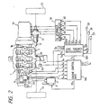
- Fig. 2 illustrates an embodiment of control system for a vehicle engine coupled with an automatic transmission according to the present invention, together with a vehicle engine which is mounted on a vehicle of the front engine - front drive type and to which the embodiment is applied.
- a vehicle engine 1 has four cylinders 2 each supplied with air-fuel mixture through an intake passage 4 provided with a throttle valve 3.
- the air-fuel mixture taken in each of the cylinders 2 is subjected to combustion caused by the operation of an ignition system including spark plugs 5, a distributor 6, an ignition coil 7 and an ignitor 8, and exhaust gas resulted from the combustion is discharged through an exhaust passage 9.
- an ignition system including spark plugs 5, a distributor 6, an ignition coil 7 and an ignitor 8
- exhaust gas resulted from the combustion is discharged through an exhaust passage 9.
- a torque is produced on a crank shaft of the vehicle engine 1.
- the torque obtained from the vehicle engine 1 is transmitted through an automatic transmission 10 which is coupled with the vehicle engine 1, a differential gear mechanism 11 and a front axle 12 to a couple of front wheels 13.
- the automatic transmission 10 is accompanied with an oil hydraulic control circuit 30 provided with solenoid valves 61, 62, 63, 64 and 65 for supplying various portions of the automatic transmission 10 selectively with operating oil pressure and, as shown in Fig. 3, comprises a torque converter 14 and a power transmitting gear arrangement 20.
- the torque converter 14 comprises a pump impeller 14a, a turbine runner 14b, a stator 14c and a case 21.
- the pump impeller 14a is secured to a crank shaft 1a of the vehicle engine 1 on which an oil pump 15 is mounted.
- the turbine runner 14b is coupled through a tubular turbine shaft 17 with the power transmitting gear arrangement 20 and coupled also through a lock-up clutch 22 with the crank shaft 1a.
- the stator 14c is coupled rotatably through a one-way clutch 19 with the case 21 and the one-way clutch 19 permits the stator 14c to revolve only in a direction common to the revolution of the pump impeller 14a.
- the power transmitting gear arrangement 20 is provided with a planetary gear unit 24 for obtaining four forward speeds and one reverse speed.
- the planetary gear unit 24 comprises a large sun gear 25, a small sun gear 26, a long pinion gear 27, a short pinion gear 28 and a ring gear 29.
- a series connection of a forward clutch 31 for forward traveling and a one-way clutch 32 is disposed in parallel with a coast clutch 33 between the small sun gear 26 and the tubular turbine shaft 17.
- a reverse clutch 35 for reverse traveling and a 2-4 brake device 36 are connected in series between the large sun gear 25 and the tubular turbine shaft 17.
- a 3-4 clutch 38 is provided between the long pinion gear 27 and the tubular turbine shaft 17, and the long pinion gear 27 is coupled through a carrier 39 of the planetary gear unit 24 and a one-way clutch 41 with a case 42 of the power transmitting gear arrangement 20.
- the carrier 39 is selectively engaged through a low/reverse brake device 44 with the case 42.
- the ring gear 29 is connected through an output shaft 45 of the planetary gear unit 24 to an output gear 47, so that the torque obtained on the output shaft 45 is transmitted through idlers or the like to the differential gear mechanism 11.
- a plurality of shift positions including P (parking) position, R (reverse) position, N (neutral) position, D (driving) position, 1st position and 2nd position, and a plurality of speed range including first to fourth speed ranges at the D position, first to third speed ranges at the 2nd position, and first and second speed ranges at the 1st position, are obtained by causing the forward clutch 31, coast clutch 33, reverse clutch 35, 3-4 clutch 38, 2-4 brake device 36 and low/reverse brake device 44, each of which is formed into an engaging friction element, to work selectively.
- the first and second speed ranges are provided with relatively large gear ratios, respectively, and the third and fourth speed ranges are provided with relatively small gear ratios, respectively.
- the gear ratios provided for the first to fourth speed ranges respectively are decreased in order.
- Table 1 Shift position Speed range Clutch Brake device One-way clutch 31 33 38 35 36 44 32 41 P R o o N D 1st speed o o o 2nd speed o o o 3rd speed o o o o 4th speed o o o (o) 2nd 1st speed o o o 2nd speed o o o o 3rd speed o o o o 1st 1st speed o o o o 2nd speed o o o o o o o o o o o
- each circular mark:o represents that the device is held in engagement to transmit power and a parenthesized circular mark:(o) represent that the device is held in engagement without participating in power transmission.
- the operating oil pressure for working each of the clutches 31, 33, 38 and 35 and the brakes 36 and 44 is produced in the oil hydraulic control circuit 30.
- an engine control unit 100 which contained a microcomputer and a transmission control unit 200 which contains also a microcomputer are provided for controlling the operation of a combination of the vehicle engine 1 and the automatic transmission 10 constituted as described above.
- the engine control unit 100 is supplied with a detection output signal Sn obtained from an engine speed sensor 51 provided on the distributor 6, a detection output signal Sc obtained from a crank angle sensor 52 provided on the distributor 6, a detection output signal Sw obtained from a temperature sensor 53 provided on an engine block 1b, a detection output signal Sk obtained from a knocking sensor 54 provided on the engine block 1b, a detection output signal St obtained from a throttle sensor 55, a detection output signal Sb obtained from a negative pressure sensor 56 disposed at a portion of the intake passage 4 downstream to the throttle valve 3 and other necessary detection output signals Sx, and operative to generate an ignition control signal SCq based on the detection output signals Sn, Sc, Sw, Sk, St and Sb and a command pulse signal Pj which is supplied selectively to the engine control unit 100 from the transmission control unit 200 and to supply the ignitor 8 with the ignition control signal SCq so as to perform an ignition timing control.
- a detection output signal Sn obtained from an engine speed sensor 51 provided on the distributor 6
- a detection output signal Sc
- the transmission control unit 200 is supplied with the detection output signal Sw from the temperature sensor 53, the detection output signal St from the throttle sensor 55, a detection output signal Su obtained from a turbine speed sensor 57, a detection output signal Sv obtained from a speed sensor 58, a detection output signal Ss obtained from a shift position sensor 59 and other necessary detection output signals Sy, and operative to supply the solenoid valves 61 to 65 respectively with driving pulse signals SCa, SCb, SCc, SCd and SCe produced based on the detection output signals Sw, St, Su, Sv and Ss so as to perform a speed change control for the automatic transmission 10 in which each of the clutches 31, 33, 38 and 35 and the brakes 36 and 44 is selectively engaged in such a manner as shown in Table 1 and further a lock-up control in which the lock-up clutch 22 provided in the torque converter 14 is selectively engaged.
- en engine load embodied by the throttle opening degree represented by the detection output signal St and the traveling speed of the vehicle represented by the detection output signal Sv are checked up on shifting-up and shifting-down lines in a predetermined speed change characteristic map, for example, as shown in Fig.
- the command pulse signal Pj is supplied to the engine control unit 100 from the transmission control unit 200 after a predetermined period, for example, 100 msec, which is selected to correspond to time lag in operation of the power transmitting gear arrangement 20, has elapsed since the second to first or third to second shifting-down operation was detected, on the condition that a different shifting-up or shifting-down operation is not detected in the predetermined period.
- a fundamental advanced angle of crank rotation corresponding to a fundamental ignition timing is determined based on the engine speed represented by the detection output signal Sn and the negative pressure in the intake passage represented by the detection output signal Sb, and when the command pulse signal Pj is supplied to the engine control unit 100 from the transmission control unit 200, a first retarding angle of crank rotation is provided for causing an actual ignition timing to be retarded compared with the fundamental ignition timing so as to suppress torque shock resulting from the speed change operation carried out in the automatic transmission 10.
- a second retarding angle of crank rotation is provided for causing the actual ignition timing to be retarded compared with the fundamental ignition timing so as to suppress the knocking.
- the command pulse signal Pj is supplied to the engine control unit 100 from the transmission control unit 200 at a time point t2 after a predetermined period Ta, which is selected to correspond to time lag in operation of the power transmitting gear arrangement 20, has lapsed from the time point t1, as shown in Fig.
- a retarding angle ⁇ A is set to have an initial value ⁇ a at the time point t2, as shown in Fig. 5C.
- the retarding angle ⁇ A is maintained to be ⁇ a during a period Tr from the time point t2 to a time point t3 in which the clutches 31, 33, 38 and 35 and the brakes 36 and 44 in the power transmitting gear arrangement 20 work selectively for the speed change operation, and then reduced step by step by a small angle ⁇ at each step after the time point t3 so as to be zero at a time point t4, as shown in Fig. 5C.
- An effective angle ⁇ of crank rotation corresponding to the actual ignition timing is obtained by subtracting the retarding angle ⁇ A from the fundamental advanced angle, so that a spark advance is reduced by the retarding angle ⁇ A in a period from the time point t2 to the time point t4. Accordingly, a torque TR produced by the vehicle engine 1 and obtained on the output shaft 45 of the automatic transmission 10 is reduced after the time point t2, as shown by a solid line in Fig. 5D, as compared with a torque obtained without the reduction in spark advance as shown in a broken line in Fig. 5D, so that the torque shock resulting from the second to first or third to second shifting-down operation is suppressed effectively.
- a retarding angle ⁇ K of crank rotation is provided to have an initial value corresponding to the magnitude of the knocking, as shown in Fig. 6C.
- a final retarding angle ⁇ R of crank rotation is formed with one of the retarding angles ⁇ A and ⁇ K which is larger than the other of the retarding angles ⁇ A and ⁇ K, as shown in 6D, and the effective angle ⁇ corresponding to the actual ignition timing is obtained by subtracting the final retarding angle ⁇ R from a fundamental advanced angle ⁇ B. Accordingly, the final retarding angle ⁇ R is prevented from being large excessively, such as shown by a broken line in Fig. 6D, under a condition in which the retarding angles ⁇ A and ⁇ K are provided simultaneously and therefore the output of the vehicle engine 1 is prevented from being reduced in excess of necessity.
- the command pulse signal Pj is not supplied to the engine control unit 100 from the transmission control unit 200 at the time point t c ′ but supplied to the engine control unit 100 from the transmission control unit 200 at a time point t d ′ after the predetermined period Ta has lapsed from the time point t b ′, as shown in Figs. 8A and 8B. Consequently, the control for suppressing torque shock caused by each second to first and third to second shifting-down operation is surely achieved under a condition in which the second to first and third to second shifting-down operation is carried out in a relatively short period.
- the control for suppressing the torque shock resulting from the speed change operation as described above is not carried out when the shifting-up operation is detected because it is not feared that the shifting-up operation brings about a relatively large torque shock on the output shaft 45 of the automatic transmission 10. Further, the control for suppressing the torque shock resulting from the speed change operation as described above is not carried out so as to prevent the torque TR from being reduced when the fourth to third shifting-down operation is detected, for the following reason.
- the 3-4 clutch 38 is maintained in engagement and thereby rotary inertia on the output shaft 45 of the automatic transmission 10 is relatively large, so that variations in torque on the output shaft 45 of the automatic transmission 10 are restricted.
- a variation in gear ratio in the power transmitting gear arrangement 20 caused by the fourth to third shifting-down operation is smaller than a variation in gear ratio in the power transmitting gear arrangement 20 caused by the second to first or third to second shifting-down operation. Consequently, it is not feared that the fourth to third shifting-down operation brings about a relatively large torque shock on the output shaft 45 of the automatic transmission 10.
- the above described speed change control by the transmission control unit 200 is effected mainly by the microcomputer contained in the transmission control unit 200 and the ignition timing control by the engine control unit 100 is effected mainly by the microcomputer contained in the engine control unit 100.
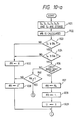
- One example of an operation program for the speed change control is carried out in the microcomputer contained in the transmission control unit 200 in accordance with a flow chart shown in Fig. 9.
- step R1 the detection output signals St, Sv, Ss and Sy are stored, and in step R2, throttle opening degree Th represented by the detection output signal St and vehicle traveling speed V represented by the detection output signal Sv are checked up on a speed change characteristic map, such as shown in Fig. 4, memorized in a memory contained in the transmission control unit 200.
- step R3 it is checked, based on a result of the checking up in the step R2, whether a speed change operation is to be performed or not. If the speed change operation is to be performed, a counted value C of a counter contained in the transmission control unit 200 is set to be 0, in step R5, and an operation program for speed change is carried out, in step R7.
- step R8 it is checked whether the speed change operation is conducted for shifting down or not.
- step R8 it is clarified in the step R8 that the speed change operation is conducted for sifting down, it is further checked whether the speed change operation is conducted for fourth to third shifting down or not, in step R9. If the speed change operation is not conducted for fourth to third shifting down, it is checked whether the throttle opening degree Th is equal to or larger than TH1 or not, in step R10. If the throttle opening degree Th is equal to or larger than TH1, it is checked whether cooling water temperature Tw represented by the detection output signal Sw is equal to or higher than TW1 or not, in step R11. If the cooling water temperature Tw is equal to or higher than TW1, the counted value C is increased by 1, in step R12,
- step R13 it is checked whether the counted value C is equal to or larger than a predetermined value A which corresponds to the predetermined period Ta or not. If the counted value C is smaller than the predetermined value A, the process returns to the step R1. On the other hand, the counted value C is equal to or larger than the predetermined value A, the command pulse signal Pj is sent out, in step R14. After that, in step R15, the counter is stopped to operate and the counted value C is set to be 0, then the process returns to the step R1.
- step R6 When it is clarified in the step R3 that the speed change operation is not to be performed, it is checked whether the counted value C is larger than 0 or not, in step R6. If the counted value C is 0, the process returns to the step R1, and if the counted value C is larger than 0, the process advances to the step R10.
- the speed change operation is conducted for fourth to third shifting down as a result of the check in the step R9
- the throttle opening degree Th is smaller than TH1 as a result of the check in the step R10, or the cooling water temperature Tw is lower than TW1 as a result of the check in the step R11
- One example of an operation program for the ignition timing control is carried out in the microcomputer contained in the engine control unit 100 in accordance with a flow chart shown in Figs. 10-a and 10-b.
- step R21 the detection output signals Sn, Sc, Sw, Sk, Sb, St and Sx are stored, and then, the fundamental advanced angle ⁇ B of crank rotation corresponding to the fundamental ignition timing is calculated based on the engine speed represented by the detection output signal Sn and the negative pressure in the intake passage represented by the detection output signal Sb, in step R22.
- step R23 it is checked whether throttle opening degree Th represented by the detection output signal St is equal to or larger than TH1 or not. If the throttle opening degree Th is equal to or larger than TH1, it is further checked whether cooling water temperature Tw is equal to or higher than TW1, in step R24. When the cooling water temperature Tw is equal to or higher than TW1, it is checked whether the command pulse signal Pj has been sent out or not, in step R26.
- step R26 If it is clarified in the step R26 that the command pulse signal Pj has been sent out, the retarding angle ⁇ A is set to have the initial value ⁇ a in step R27, and a flag FR is set to be 1 in step R28. After that, a counted value U of a counter contained in the engine control unit 100 is set to be 0 in step R29, and the process advances to step R31.
- step R31 the retarding angle ⁇ K, which is determined in another operation program for determining the retarding angle described later, is stored. Then, in step R32, it is checked whether the retarding angle ⁇ A is larger than the retarding angle ⁇ K or not. If the the retarding angle ⁇ A is larger than the retarding angle ⁇ K, the retarding angle ⁇ A is adopted as the final retarding angle ⁇ R, in step R33, and if the retarding angle ⁇ A is equal to or smaller than the retarding angle ⁇ K, the retarding angle ⁇ K is adopted as the final retarding angle ⁇ R, in step R34.
- step R35 the ignition control signal SCq which corresponds to the effective angle ⁇ obtained in the step R36 is produced and sent out to the ignitor 8, and thereafter, the process returns to the step R21.
- the flag FR is set to be 0 in step R37 and the retarding angle ⁇ A is set to be 0° in step R38. Then, the process advances to the step R31.
- step R26 when it is clarified in the step R26 that the command pulse signal Pj has not been sent out, it is checked whether the flag FR is set to be 1 or not, in step R40. If the flag FR is set to be 0, the process advances to the step R38, and if the flag FR is set to be 1, the process advances to step R41.
- step R41 the counted value U is increased by 1, and then it is checked whether the counted value U is equal to or larger than a predetermined value E which is set to correspond to the period Tr, in step R42. If the counted value U is equal to or larger than the predetermined value E, the retarding angle ⁇ A is renewed by subtracting the small angle ⁇ , in step 43, and it is checked whether the retarding angle ⁇ A renewed in the step R43 is smaller than 0°, namely, negative or not, in step R44.
- the process advances to the step R32. If the retarding angle ⁇ A is equal to or larger than 0 as a result of the check in the step R44, the process advances to the step R46 directly from the step R44. Further, if the counted value U is smaller than the predetermined value E, the process advances to the step R32 directly from the step R42.
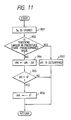
- the operation program for determining the retarding angles ⁇ K is carried out in accordance with a flow chart shown in Fig. 11 in the microcomputer contained in the engine control unit 100.
- step R51 the detection output signal Sk is stored, and it is checked based on the detection output signal Sk whether the knocking in the vehicle engine 1 is larger in magnitude than a predetermined value or not, in step R52. If the knocking in the vehicle engine 1 is larger in magnitude than the predetermined value, the retarding angle ⁇ K is determined in response to the magnitude of the knocking, in step R53, and the process returns to the step R51.
- the retarding angle ⁇ K is renewed by subtracting the small angle ⁇ , in step R54. Then, it is checked whether the retarding angle ⁇ K is smaller than 0°, namely, negative or not, in step R55. If the retarding angle ⁇ K is smaller than 0°, the retarding angle ⁇ K is set to be 0°, in step R56, and then the process returns to the step R51. Further, if the retarding angle ⁇ K is equal to or larger than 0° as a result of the check in the step R55, the process returns to the step R51 directly from the step R55.
- the retarding angle ⁇ A is set to be 0 by the engine control unit 100 when the fourth to third shifting-down operation carried out in the automatic transmission 10 is detected by the transmission control unit 200 and the command pulse signal Pj is not supplied from the transmission control unit 200 to the engine control unit 100
- the engine control unit 100 can be arranged to set the retarding angle ⁇ A to be a value smaller than a value provided for the retarding angle ⁇ A on the occasion where the second to first or third to second shifting-down is detected, so as to restrict the reduction of the torque TR caused by the ignition timing control when the fourth to third shifting-down operation is detected by the transmission control unit 200.
- the ignition timing is controlled by the engine control unit 100 for reducing the torque TR so as to suppress the torque shock resulting from the speed change operation and the knocking in the vehicle engine 1 in the above described embodiment
- the engine control unit 100 can be arranged to control one or more controllable subjects other than the ignition timing, for example, fuel supply to the vehicle engine 1 or intake air mass flow to the vehicle engine 1, for reducing the torque TR so as to suppress the torque shock resulting from the speed change operation and the knocking in the vehicle engine 1.
Abstract
Description
- The present invention relates generally to control systems for vehicle engines coupled with automatic transmissions, and more particularly, to a system for controlling an output of a vehicle engine which is coupled with an automatic transmission employed in a vehicle so as to suppress torque shocks brought about by speed change operations performed in the automatic transmission.
- There has been commonly used in vehicles an automatic transmission which is coupled with an engine provided in the vehicle and includes a torque converter comprising a pump impeller, a turbine runner and a stator, and a power transmitting gear arrangement including a speed change mechanism connected to the turbine runner in the torque converter. Such an automatic transmission employed to be coupled with the engine in the vehicle is usually accompanied with a hydraulic pressure control device including an oil hydraulic control circuit, by which engaging friction elements, such as clutch and brake elements, operating with oil pressure in the speed change mechanism are caused to work for a speed change operation.
- When the speed change operation is carried out in the automatic transmission accompanied with the hydraulic pressure control device, sudden rise or down in speed of the engine is caused in response to variations in gear ratio in the speed change mechanism and thereby sudden variations in torque are caused on an output shaft of the automatic transmission. This results in that torque shock on the vehicle is brought about by each speed change operation performed in the automatic transmission.
- With the intention of suppressing the torque shock resulting from the speed change operation, it is considered to adjust oil pressure applied to the engaging friction elements so that each engaging friction element comes into engagement or disengagement gradually and smoothly. In such a case, however, a period of time in which the engaging friction element is kept in a slipping condition in process of the speed change operation is protracted and therefore it is feared that the engaging friction element is subjected to seizing and abrasion of great degree.
- In view of this, there has been proposed to reduce torque produced by the engine (engine torque) for a predetermined duration on the occasion of the speed change operation so as to suppress the torque shock resulting from the speed change operation, as disclosed in, for example, the Japanese patent application published before examination under publication number 61-104128. In the case where the engine torque is thus reduced for suppressing the torque shocks, for example, ignition timing is selected as a controlled subject for varying the engine torque and controlled to be retarded, compared with a normal ignition timing, so as to reduce the engine torque during the speed change operation.
- Usually, in the vehicle which is equipped with the engine coupled with the automatic transmission, a variation in gear ratio in the speed change mechanism caused on the occasion of a speed change between high speed ranges each provided with a relatively small gear ratio is smaller than a variation in gear ratio in the speed change mechanism caused on the occasion of a speed change between low speed ranges each provided with a relatively large gear ratio. Further, in a condition in which the high speed range is taken in the speed change mechanism, rotary inertia on an output shaft of the automatic transmission is relatively large compared with that in a condition in which the low speed range is taken in the speed change mechanism, so that variations in torque on the output shaft of the automatic transmission are restricted and therefore the torque shock on the vehicle is substantially reduced.
- Besides, when the high speed range is taken in the speed change mechanism, the vehicle is, in general, traveling at high speed and therefore it is to be understood that to prevent the engine torque from being reduced takes precedence of to suppress the torque shock resulting from the speed change operation. Especially, in the case where a shifting-down operation for causing a change from a speed range of the smallest gear ratio, for example, the fourth speed range to a speed range of the second smallest gear ratio, for example, the third speed change is carried out in the automatic transmission, the vehicle is likely to require to be accelerated to pass another vehicle ahead and therefore it is desirable that the control for reducing the engine torque so as to suppress the torque shock resulting from the speed change operation is not performed.
- However, in the prior art, the above mentioned differences between the speed change operation causing the change from one to another of the low speed ranges and the speed change operation causing the change from one to another of the high speed ranges, has not been taken into consideration and a controlled variable in the control for reducing the engine torque so as to suppress the torque shock resulting from the speed change operation is set to be constant regardless of a mode of the speed change operation. Accordingly, in the case where the speed change between the high speed ranges is brought about in the automatic transmission, it is feared that the controlled variable in the control for reducing the engine torque so as to suppress the torque shock resulting from the speed change operation is large excessively and thereby excessive reduction of the engine torque is induced so that required engine torque can not be obtained.
- Accordingly, it is an object of the present invention to provide a control system for a vehicle engine coupled with an automatic transmission, in which a control for varying torque produced by the vehicle engine so as to suppress torque shock resulting from a speed change operation carried out in the automatic transmission are performed, and which avoids the aforementioned disadvantages and problems encountered with the prior art.
- Another object of the present invention to provide a control system for a vehicle engine coupled with an automatic transmission, in which a control for varying torque produced by the vehicle engine so as to suppress torque shock resulting from a speed change operation carried out in the automatic transmission is performed and the torque shock is suppressed sufficiently without inducing excessive reduction of the torque produced by the vehicle engine on the occasion of the speed change operation.
- In accordance with the present invention, there is provided a control system for a vehicle engine coupled with an automatic transmission comprising a torque controller operative to vary torque produced by the vehicle engine, in accordance with a controlled variable determined for controlling the torque, so as to suppress torque shock resulting from a speed change operation carried out in the automatic transmission, a speed change operation detector for detecting the speed change operation carried out to vary a gear ratio in a power transmitting gear arrangement provided in the automatic transmission, a controlled variable setting device for determining the controlled variable based on an operating condition of the vehicle engine and the speed change operation carried out in the automatic transmission, and a controlled variable revising device for varying the controlled variable so as to reduce variation in the torque brought about by the torque controller under a condition in which the speed change operation causing a change from one to another of speed ranges of relatively small gear ratios is detected by the speed change operation detector, as compared with variation in the torque brought about by the torque controller under a condition in which the speed change operation causing a change from one to another of speed ranges of relatively large gear ratios is detected by the speed change operation detector.
- In one embodiment control system for a vehicle engine coupled with an automatic transmission according to the present invention, the controlled variable revising device is operative to vary the controlled variable so as to cause the variation in the torque brought about by the torque controller to be substantially zero when a shifting-down operation causing a change from a speed range of the smallest gear ratio to a speed range of the second smallest gear ratio is detected by the speed change operation detector.
- With the control system thus constituted in accordance the present invention, on the occasion of the speed change operation carried out to cause the change between the speed ranges of relatively large gear ratios in the automatic transmission, the variation in the torque produced by the vehicle engine is brought about by the torque controller without being reduced and thereby the torque shock resulting from the speed change operation is suppressed sufficiently. On the other hand, when the speed change operation is carried out to cause the change between the speed ranges of relatively small gear ratios in the automatic transmission and therefore the torque shock resulting from the speed change operation is substantially reduced, the variation in the torque brought about by the torque controller is reduced so as to restrain reduction of the torque and thereby excessive reduction of the torque produced by the vehicle engine is prevented so that required torque can be obtained from the vehicle engine.
- The above, and other objects, features and advantages of the present invention will become apparent from the following detailed description which is to be read in conjunction with the accompanying drawings.
-
- Fig. 1 is a block diagram illustrating the basic arrangement of a control system for a vehicle engine coupled with an automatic transmission according to the present invention;
- Fig. 2 is a schematic illustration showing one embodiment of control system for a vehicle engine coupled with an automatic transmission according to the present invention, together with essential portions of a vehicle engine to which the embodiment is applied;
- Fig. 3 is a schematic illustration showing an example of an automatic transmission accompanying with the engine to which the embodiment shown in Fig. 2 is applied;
- Fig. 4 shows a speed change characteristic map used for explaining the operation of the embodiment shown in Fig. 2;
- Figs. 5A to 5D, 6A to 6D, 7A, 7B, 8A and 8B are time charts used for explaining the operation of the embodiment shown in Fig. 2; and
- Figs. 9, 10-a, 10-b and 11 are flow charts showing examples of operational programs for a microcomputer used in a control unit employed in the embodiment shown in Fig. 2.
- Fig. 1 illustrates a functional block diagram of a system incorporating the present invention. In the functional block diagram of Fig. 1, the system comprises a vehicle engine B1 coupled with an automatic transmission B2, a speed change operation detector B3, a controlled variable setting section B4, a torque controller B5, and a controlled variable revising section B6.
- The speed change operation detector B3 is operative to detect a speed change operation carried out to vary a gear ratio in a power transmitting gear arrangement provided in the automatic transmission B2. The controlled variable setting section B4 is operative to determine a controlled variable for controlling torque produced by the vehicle engine B1 based on an operating condition of the vehicle engine B1 and the speed change operation carried out in the automatic transmission B2. The torque controller B5 is operative to vary the torque produced by the vehicle engine B1, in response to the controlled variable which is determined by the controlled variable setting section B4, so as to suppress torque shock resulting from the speed change operation carried out in the automatic transmission B2. Then, the controlled variable revising section B6 is operative to vary the controlled variable, which is determined by the controlled variable setting section B4, so as to reduce variation in the torque brought about by the torque controller B5 under a condition in which the speed change operation causing a change from one to another of speed ranges of relatively small gear ratios is detected by the speed change operation detector B3, as compared with variation in the torque brought about by the torque controller B5 under a condition in which the speed change operation causing a change from one to another of speed ranges of relatively large gear ratios is detected by the speed change operation detector B3.
- Fig. 2 illustrates an embodiment of control system for a vehicle engine coupled with an automatic transmission according to the present invention, together with a vehicle engine which is mounted on a vehicle of the front engine - front drive type and to which the embodiment is applied.
- Referring to Fig. 2, a
vehicle engine 1 has fourcylinders 2 each supplied with air-fuel mixture through an intake passage 4 provided with athrottle valve 3. The air-fuel mixture taken in each of thecylinders 2 is subjected to combustion caused by the operation of an ignition system includingspark plugs 5, a distributor 6, anignition coil 7 and anignitor 8, and exhaust gas resulted from the combustion is discharged through anexhaust passage 9. With such combustion of the air-fuel mixture in each of thecylinders 2, a torque is produced on a crank shaft of thevehicle engine 1. The torque obtained from thevehicle engine 1 is transmitted through anautomatic transmission 10 which is coupled with thevehicle engine 1, a differential gear mechanism 11 and afront axle 12 to a couple offront wheels 13. - The
automatic transmission 10 is accompanied with an oilhydraulic control circuit 30 provided withsolenoid valves automatic transmission 10 selectively with operating oil pressure and, as shown in Fig. 3, comprises atorque converter 14 and a powertransmitting gear arrangement 20. Thetorque converter 14 comprises a pump impeller 14a, aturbine runner 14b, a stator 14c and a case 21. The pump impeller 14a is secured to acrank shaft 1a of thevehicle engine 1 on which an oil pump 15 is mounted. Theturbine runner 14b is coupled through atubular turbine shaft 17 with the power transmittinggear arrangement 20 and coupled also through a lock-up clutch 22 with thecrank shaft 1a. The stator 14c is coupled rotatably through a one-way clutch 19 with the case 21 and the one-way clutch 19 permits the stator 14c to revolve only in a direction common to the revolution of the pump impeller 14a. - The power transmitting
gear arrangement 20 is provided with aplanetary gear unit 24 for obtaining four forward speeds and one reverse speed. Theplanetary gear unit 24 comprises alarge sun gear 25, asmall sun gear 26, along pinion gear 27, ashort pinion gear 28 and aring gear 29. A series connection of aforward clutch 31 for forward traveling and a one-way clutch 32 is disposed in parallel with acoast clutch 33 between thesmall sun gear 26 and thetubular turbine shaft 17. Areverse clutch 35 for reverse traveling and a 2-4brake device 36 are connected in series between thelarge sun gear 25 and thetubular turbine shaft 17. A 3-4clutch 38 is provided between thelong pinion gear 27 and thetubular turbine shaft 17, and thelong pinion gear 27 is coupled through acarrier 39 of theplanetary gear unit 24 and a one-way clutch 41 with acase 42 of the power transmittinggear arrangement 20. Thecarrier 39 is selectively engaged through a low/reverse brake device 44 with thecase 42. Thering gear 29 is connected through anoutput shaft 45 of theplanetary gear unit 24 to anoutput gear 47, so that the torque obtained on theoutput shaft 45 is transmitted through idlers or the like to the differential gear mechanism 11. - In the power transmitting
gear arrangement 20 constituted as described above, a plurality of shift positions including P (parking) position, R (reverse) position, N (neutral) position, D (driving) position, 1st position and 2nd position, and a plurality of speed range including first to fourth speed ranges at the D position, first to third speed ranges at the 2nd position, and first and second speed ranges at the 1st position, are obtained by causing theforward clutch 31,coast clutch 33,reverse clutch 35, 3-4clutch 38, 2-4brake device 36 and low/reverse brake device 44, each of which is formed into an engaging friction element, to work selectively. The first and second speed ranges are provided with relatively large gear ratios, respectively, and the third and fourth speed ranges are provided with relatively small gear ratios, respectively. The gear ratios provided for the first to fourth speed ranges respectively are decreased in order. - In the following Table 1, there are given the relationship in operation of the respective shift positions and speed ranges with the clutches and brake devices in the above configuration:
Table 1 Shift position Speed range Clutch Brake device One- way clutch 31 33 38 35 36 44 32 41 P R o o N D 1st speed o o o 2nd speed o o o 3rd speed o o o o 4th speed o o o (o) 2nd 1st speed o o o 2nd speed o o o o 3rd speed o o o o 1st 1st speed o o o o 2nd speed o o o o - In Table 1, each circular mark:o represents that the device is held in engagement to transmit power and a parenthesized circular mark:(o) represent that the device is held in engagement without participating in power transmission.
- The operating oil pressure for working each of the
clutches brakes hydraulic control circuit 30. - In the embodiment shown in Fig. 2, an
engine control unit 100 which contained a microcomputer and a transmission control unit 200 which contains also a microcomputer are provided for controlling the operation of a combination of thevehicle engine 1 and theautomatic transmission 10 constituted as described above. - The
engine control unit 100 is supplied with a detection output signal Sn obtained from anengine speed sensor 51 provided on the distributor 6, a detection output signal Sc obtained from acrank angle sensor 52 provided on the distributor 6, a detection output signal Sw obtained from a temperature sensor 53 provided on anengine block 1b, a detection output signal Sk obtained from aknocking sensor 54 provided on theengine block 1b, a detection output signal St obtained from athrottle sensor 55, a detection output signal Sb obtained from anegative pressure sensor 56 disposed at a portion of the intake passage 4 downstream to thethrottle valve 3 and other necessary detection output signals Sx, and operative to generate an ignition control signal SCq based on the detection output signals Sn, Sc, Sw, Sk, St and Sb and a command pulse signal Pj which is supplied selectively to theengine control unit 100 from the transmission control unit 200 and to supply theignitor 8 with the ignition control signal SCq so as to perform an ignition timing control. - The transmission control unit 200 is supplied with the detection output signal Sw from the temperature sensor 53, the detection output signal St from the
throttle sensor 55, a detection output signal Su obtained from aturbine speed sensor 57, a detection output signal Sv obtained from aspeed sensor 58, a detection output signal Ss obtained from ashift position sensor 59 and other necessary detection output signals Sy, and operative to supply thesolenoid valves 61 to 65 respectively with driving pulse signals SCa, SCb, SCc, SCd and SCe produced based on the detection output signals Sw, St, Su, Sv and Ss so as to perform a speed change control for theautomatic transmission 10 in which each of theclutches brakes torque converter 14 is selectively engaged. - On the occasion of the speed change control, in the transmission control unit 200, en engine load embodied by the throttle opening degree represented by the detection output signal St and the traveling speed of the vehicle represented by the detection output signal Sv are checked up on shifting-up and shifting-down lines in a predetermined speed change characteristic map, for example, as shown in Fig. 4, which has shifting-up lines a, b, and c for first to second shifting up (1 → 2), second to third shifting up (2 → 3) and third to fourth shifting up (3 → 4), respectively, and shifting-down lines d, e and f for second to first shifting down (2 → 1), third to second shifting down (3 → 2) and fourth to third shifting down (4 → 3), and a first to second shifting-up operation which causes a change from the first speed range to the second speed range, a second to third shifting-up operation which causes a change from the second speed range to the third speed range, a third to fourth shifting-up operation which causes a change from the third speed range to the fourth speed range, a second to first shifting-down operation which causes a change from the second speed range to the first speed range, a third to second shifting-down operation which causes a change from the third speed range to the second speed range, or a fourth to third shifting-down operation which causes a change from the fourth speed range to the third speed range is detected based on a result of the checking up.
- When one of the shifting-down operations except the fourth to third shifting-down operation, that is, the second to first shifting-down operation or the third to second shifting-down operation which is apt to cause relatively large torque shock on the vehicle, is detected under a condition in which the
vehicle engine 1 is operating with, for example, the throttle opening degree which is equal to or larger than TH₁ corresponding to one eighth the maximum value and the cooling water temperature which is equal to or higher than TW₁ set to be equal to or higher than 70°C, the command pulse signal Pj is supplied to theengine control unit 100 from the transmission control unit 200 after a predetermined period, for example, 100 msec, which is selected to correspond to time lag in operation of the powertransmitting gear arrangement 20, has elapsed since the second to first or third to second shifting-down operation was detected, on the condition that a different shifting-up or shifting-down operation is not detected in the predetermined period. - In the ignition timing control by the
engine control unit 100, a fundamental advanced angle of crank rotation corresponding to a fundamental ignition timing is determined based on the engine speed represented by the detection output signal Sn and the negative pressure in the intake passage represented by the detection output signal Sb, and when the command pulse signal Pj is supplied to theengine control unit 100 from the transmission control unit 200, a first retarding angle of crank rotation is provided for causing an actual ignition timing to be retarded compared with the fundamental ignition timing so as to suppress torque shock resulting from the speed change operation carried out in theautomatic transmission 10. Further, when the knocking in thevehicle engine 1 represented by the detection output signal Sk is larger in magnitude than a predetermined value, a second retarding angle of crank rotation is provided for causing the actual ignition timing to be retarded compared with the fundamental ignition timing so as to suppress the knocking. - Under a condition in which the speed change control and the ignition timing control are thus carried out by the transmission control unit 200 and the
engine control unit 100, respectively, in the case where a throttle opening degree Th is commenced to increase at a time point t₀ and the second to first or third to second shifting-down operation is detected at a time point t₁, as shown in Fig. 5A, the command pulse signal Pj is supplied to theengine control unit 100 from the transmission control unit 200 at a time point t₂ after a predetermined period Ta, which is selected to correspond to time lag in operation of the powertransmitting gear arrangement 20, has lapsed from the time point t₁, as shown in Fig. 5B, and a retarding angle ϑA is set to have an initial value ϑa at the time point t₂, as shown in Fig. 5C. The retarding angle ϑA is maintained to be ϑa during a period Tr from the time point t₂ to a time point t₃ in which theclutches brakes transmitting gear arrangement 20 work selectively for the speed change operation, and then reduced step by step by a small angle Δϑ at each step after the time point t₃ so as to be zero at a time point t₄, as shown in Fig. 5C. An effective angle ϑ of crank rotation corresponding to the actual ignition timing is obtained by subtracting the retarding angle ϑA from the fundamental advanced angle, so that a spark advance is reduced by the retarding angle ϑA in a period from the time point t₂ to the time point t₄. Accordingly, a torque TR produced by thevehicle engine 1 and obtained on theoutput shaft 45 of theautomatic transmission 10 is reduced after the time point t₂, as shown by a solid line in Fig. 5D, as compared with a torque obtained without the reduction in spark advance as shown in a broken line in Fig. 5D, so that the torque shock resulting from the second to first or third to second shifting-down operation is suppressed effectively. - In the case where the command pulse signal Pj is supplied to the
engine control unit 100 from the transmission control unit 200 and thereby the retarding angle ϑA is set to have the initial value ϑa at a time point t₁′, as shown in Figs. 6A and 6B, and a knocking which is larger in magnitude than a predetermined value arises in thevehicle engine 1 at a time point t₂′ immediately after the time point t₁′, a retarding angle ϑK of crank rotation is provided to have an initial value corresponding to the magnitude of the knocking, as shown in Fig. 6C. In such a case, a final retarding angle ϑR of crank rotation is formed with one of the retarding angles ϑA and ϑK which is larger than the other of the retarding angles ϑA and ϑK, as shown in 6D, and the effective angle ϑ corresponding to the actual ignition timing is obtained by subtracting the final retarding angle ϑR from a fundamental advanced angle ϑB. Accordingly, the final retarding angle ϑR is prevented from being large excessively, such as shown by a broken line in Fig. 6D, under a condition in which the retarding angles ϑA and ϑK are provided simultaneously and therefore the output of thevehicle engine 1 is prevented from being reduced in excess of necessity. - In the case where the second to first or third to second shifting-down is detected at a time point ta and the command pulse signal Pj is supplied to the
engine control unit 100 from the transmission control unit 200 so that the retarding angle ϑA is set to have the initial value ϑa at a time point tb after the predetermined period Ta has lapsed from the time point ta, as shown in Figs. 7A and 7B, and then a further second to first or third to second shifting-down operation is newly detected at a time point tc immediately after the time point tb, the command pulse signal Pj is again supplied to theengine control unit 100 from the transmission control unit 200 and the retarding angle ϑA is reset to have the initial value ϑa at a time point td after the predetermined period Ta has lapsed from the time point tc, as shown in Figs. 7A and 7B. Accordingly, the control for suppressing torque shock caused by each second to first or third to second shifting-down operation is surely achieved. - Further, in the case where the second to first or third to second shifting-down operation is detected at a time point ta′ and the next second to first or third to second shifting-down operation is detected at a time point tb′ before a time point tc′ at which the predetermined period Ta has lapsed from the time point ta′, as shown in Figs. 8A and 8B, the command pulse signal Pj is not supplied to the
engine control unit 100 from the transmission control unit 200 at the time point tc′ but supplied to theengine control unit 100 from the transmission control unit 200 at a time point td′ after the predetermined period Ta has lapsed from the time point tb′, as shown in Figs. 8A and 8B. Consequently, the control for suppressing torque shock caused by each second to first and third to second shifting-down operation is surely achieved under a condition in which the second to first and third to second shifting-down operation is carried out in a relatively short period. - The control for suppressing the torque shock resulting from the speed change operation as described above is not carried out when the shifting-up operation is detected because it is not feared that the shifting-up operation brings about a relatively large torque shock on the
output shaft 45 of theautomatic transmission 10. Further, the control for suppressing the torque shock resulting from the speed change operation as described above is not carried out so as to prevent the torque TR from being reduced when the fourth to third shifting-down operation is detected, for the following reason. In a condition in which the third or fourth speed range is taken in the powertransmitting gear arrangement 20, the 3-4clutch 38 is maintained in engagement and thereby rotary inertia on theoutput shaft 45 of theautomatic transmission 10 is relatively large, so that variations in torque on theoutput shaft 45 of theautomatic transmission 10 are restricted. In addition to this, a variation in gear ratio in the powertransmitting gear arrangement 20 caused by the fourth to third shifting-down operation is smaller than a variation in gear ratio in the powertransmitting gear arrangement 20 caused by the second to first or third to second shifting-down operation. Consequently, it is not feared that the fourth to third shifting-down operation brings about a relatively large torque shock on theoutput shaft 45 of theautomatic transmission 10. - The above described speed change control by the transmission control unit 200 is effected mainly by the microcomputer contained in the transmission control unit 200 and the ignition timing control by the
engine control unit 100 is effected mainly by the microcomputer contained in theengine control unit 100. - One example of an operation program for the speed change control is carried out in the microcomputer contained in the transmission control unit 200 in accordance with a flow chart shown in Fig. 9.
- According to the flow chart shown in Fig. 9, first, in step R1, the detection output signals St, Sv, Ss and Sy are stored, and in step R2, throttle opening degree Th represented by the detection output signal St and vehicle traveling speed V represented by the detection output signal Sv are checked up on a speed change characteristic map, such as shown in Fig. 4, memorized in a memory contained in the transmission control unit 200. Then, in step R3, it is checked, based on a result of the checking up in the step R2, whether a speed change operation is to be performed or not. If the speed change operation is to be performed, a counted value C of a counter contained in the transmission control unit 200 is set to be 0, in step R5, and an operation program for speed change is carried out, in step R7.
- After that, in step R8, it is checked whether the speed change operation is conducted for shifting down or not. When it is clarified in the step R8 that the speed change operation is conducted for sifting down, it is further checked whether the speed change operation is conducted for fourth to third shifting down or not, in step R9. If the speed change operation is not conducted for fourth to third shifting down, it is checked whether the throttle opening degree Th is equal to or larger than TH₁ or not, in step R10. If the throttle opening degree Th is equal to or larger than TH₁, it is checked whether cooling water temperature Tw represented by the detection output signal Sw is equal to or higher than TW₁ or not, in step R11. If the cooling water temperature Tw is equal to or higher than TW₁, the counted value C is increased by 1, in step R12,
- Then, in step R13, it is checked whether the counted value C is equal to or larger than a predetermined value A which corresponds to the predetermined period Ta or not. If the counted value C is smaller than the predetermined value A, the process returns to the step R1. On the other hand, the counted value C is equal to or larger than the predetermined value A, the command pulse signal Pj is sent out, in step R14. After that, in step R15, the counter is stopped to operate and the counted value C is set to be 0, then the process returns to the step R1.
- When it is clarified in the step R3 that the speed change operation is not to be performed, it is checked whether the counted value C is larger than 0 or not, in step R6. If the counted value C is 0, the process returns to the step R1, and if the counted value C is larger than 0, the process advances to the step R10.
- Further, in the case where the speed change operation is not conducted for shifting down as a result of the check in the step R8, the speed change operation is conducted for fourth to third shifting down as a result of the check in the step R9, the throttle opening degree Th is smaller than TH₁ as a result of the check in the step R10, or the cooling water temperature Tw is lower than TW₁ as a result of the check in the step R11, it is checked whether the counted value C is 0 or not, in step R16. If the counted value C is not 0, the process advances to the step R15, and if the counted value C is 0, the process returns to the step R1.
- One example of an operation program for the ignition timing control is carried out in the microcomputer contained in the
engine control unit 100 in accordance with a flow chart shown in Figs. 10-a and 10-b. - According to the flow chart shown in Figs. 10-a and 10-b, first, in step R21, the detection output signals Sn, Sc, Sw, Sk, Sb, St and Sx are stored, and then, the fundamental advanced angle ϑB of crank rotation corresponding to the fundamental ignition timing is calculated based on the engine speed represented by the detection output signal Sn and the negative pressure in the intake passage represented by the detection output signal Sb, in step R22.
- Next, in step R23, it is checked whether throttle opening degree Th represented by the detection output signal St is equal to or larger than TH₁ or not. If the throttle opening degree Th is equal to or larger than TH₁, it is further checked whether cooling water temperature Tw is equal to or higher than TW₁, in step R24. When the cooling water temperature Tw is equal to or higher than TW₁, it is checked whether the command pulse signal Pj has been sent out or not, in step R26.
- If it is clarified in the step R26 that the command pulse signal Pj has been sent out, the retarding angle ϑA is set to have the initial value ϑa in step R27, and a flag FR is set to be 1 in step R28. After that, a counted value U of a counter contained in the
engine control unit 100 is set to be 0 in step R29, and the process advances to step R31. - In the step R31, the retarding angle ϑK, which is determined in another operation program for determining the retarding angle described later, is stored. Then, in step R32, it is checked whether the retarding angle ϑA is larger than the retarding angle ϑK or not. If the the retarding angle ϑA is larger than the retarding angle ϑK, the retarding angle ϑA is adopted as the final retarding angle ϑR, in step R33, and if the retarding angle ϑA is equal to or smaller than the retarding angle ϑK, the retarding angle ϑK is adopted as the final retarding angle ϑR, in step R34.
- After the retarding angle ϑA or ϑK is adopted as the final retarding angle ϑR, the effective angle ϑ of crank rotation corresponding to the actual ignition timing is calculated by subtracting the final retarding angle ϑR from the fundamental advanced angle ϑB, in step R35. Then, in step R36, the ignition control signal SCq which corresponds to the effective angle ϑ obtained in the step R36 is produced and sent out to the
ignitor 8, and thereafter, the process returns to the step R21. - In the case where the throttle opening degree Th is smaller than TH₁ as a result of the check in the step R23 or the cooling water temperature Tw is lower than TW₁ as a result of the check in the step R24, the flag FR is set to be 0 in step R37 and the retarding angle ϑA is set to be 0° in step R38. Then, the process advances to the step R31.
- Further, when it is clarified in the step R26 that the command pulse signal Pj has not been sent out, it is checked whether the flag FR is set to be 1 or not, in step R40. If the flag FR is set to be 0, the process advances to the step R38, and if the flag FR is set to be 1, the process advances to step R41.
- In the step R41, the counted value U is increased by 1, and then it is checked whether the counted value U is equal to or larger than a predetermined value E which is set to correspond to the period Tr, in step R42. If the counted value U is equal to or larger than the predetermined value E, the retarding angle ϑA is renewed by subtracting the small angle Δϑ, in step 43, and it is checked whether the retarding angle ϑA renewed in the step R43 is smaller than 0°, namely, negative or not, in step R44. If the retarding angle ϑA renewed in the step R43 is smaller than 0°, the retarding angle ϑA is set to be 0° in step R45, and the flag FR is set to be 0 in step R46, then the process advances to the step R32. If the retarding angle ϑA is equal to or larger than 0 as a result of the check in the step R44, the process advances to the step R46 directly from the step R44. Further, if the counted value U is smaller than the predetermined value E, the process advances to the step R32 directly from the step R42.
- The operation program for determining the retarding angles ϑK is carried out in accordance with a flow chart shown in Fig. 11 in the microcomputer contained in the
engine control unit 100. - According to the flow chart shown in Fig. 11, in step R51, the detection output signal Sk is stored, and it is checked based on the detection output signal Sk whether the knocking in the
vehicle engine 1 is larger in magnitude than a predetermined value or not, in step R52. If the knocking in thevehicle engine 1 is larger in magnitude than the predetermined value, the retarding angle ϑK is determined in response to the magnitude of the knocking, in step R53, and the process returns to the step R51. - To the contrary, when it is clarified in the step R52 that the knocking in the
vehicle engine 1 is not larger in magnitude than the predetermined value, the retarding angle ϑK is renewed by subtracting the small angle Δϑ, in step R54. Then, it is checked whether the retarding angle ϑK is smaller than 0°, namely, negative or not, in step R55. If the retarding angle ϑK is smaller than 0°, the retarding angle ϑK is set to be 0°, in step R56, and then the process returns to the step R51. Further, if the retarding angle ϑK is equal to or larger than 0° as a result of the check in the step R55, the process returns to the step R51 directly from the step R55. - Although, in the above described embodiment, the retarding angle ϑA is set to be 0 by the
engine control unit 100 when the fourth to third shifting-down operation carried out in theautomatic transmission 10 is detected by the transmission control unit 200 and the command pulse signal Pj is not supplied from the transmission control unit 200 to theengine control unit 100, theengine control unit 100 can be arranged to set the retarding angle ϑA to be a value smaller than a value provided for the retarding angle ϑA on the occasion where the second to first or third to second shifting-down is detected, so as to restrict the reduction of the torque TR caused by the ignition timing control when the fourth to third shifting-down operation is detected by the transmission control unit 200. - Further, although the ignition timing is controlled by the
engine control unit 100 for reducing the torque TR so as to suppress the torque shock resulting from the speed change operation and the knocking in thevehicle engine 1 in the above described embodiment, theengine control unit 100 can be arranged to control one or more controllable subjects other than the ignition timing, for example, fuel supply to thevehicle engine 1 or intake air mass flow to thevehicle engine 1, for reducing the torque TR so as to suppress the torque shock resulting from the speed change operation and the knocking in thevehicle engine 1.
Claims (13)
characterized by controlled variable revising means in the engine control unit (100) for varying said controlled variable so as to reduce variation in the torque brought about by said torque controlling means under a condition in which the speed change operation causing a change from one to another of speed ranges of relatively small gear ratios is detected by said detecting means, as compared with variation in the torque brought about by said torque controlling means under a condition in which the speed change operation causing a change from one to another of speed ranges of relatively large gear ratios is detectedby said detecting means.
characterized by controlled variable revising means in the engine control unit (100) for varying said controlled variable into a first revised controlled variable which is supplied to said torque controlling means to bring about a first variation in the torque when the speed change operation causing a change from one to another of speed ranges of relatively large gear ratios is detected by said detecting means and a second revised controlled variable which is also supplied to said torque control means to bring about a second variation in the torque smaller then the first variation in the torque when the speed change operation causing a change from one to another of speed ranges of relatively small gear ratios is detected by said detecting means.
Applications Claiming Priority (2)
| Application Number | Priority Date | Filing Date | Title |
|---|---|---|---|
| JP63121199A JPH0730721B2 (en) | 1988-05-18 | 1988-05-18 | Engine control device in vehicle with automatic transmission |
| JP121199/88 | 1988-05-18 |
Publications (3)
| Publication Number | Publication Date |
|---|---|
| EP0342643A2 true EP0342643A2 (en) | 1989-11-23 |
| EP0342643A3 EP0342643A3 (en) | 1990-01-31 |
| EP0342643B1 EP0342643B1 (en) | 1995-02-01 |
Family
ID=14805319
Family Applications (1)
| Application Number | Title | Priority Date | Filing Date |
|---|---|---|---|
| EP89108859A Expired - Lifetime EP0342643B1 (en) | 1988-05-18 | 1989-05-17 | Control systems for vehicle engines coupled with automatic transmissions |
Country Status (4)
| Country | Link |
|---|---|
| US (1) | US4938100A (en) |
| EP (1) | EP0342643B1 (en) |
| JP (1) | JPH0730721B2 (en) |
| DE (1) | DE68920904T2 (en) |
Cited By (4)
| Publication number | Priority date | Publication date | Assignee | Title |
|---|---|---|---|---|
| EP0362885A2 (en) * | 1988-10-07 | 1990-04-11 | Mazda Motor Corporation | Gear-shifting shock suppressing system for automatic transmission vehicle |
| EP0573901A1 (en) * | 1992-06-10 | 1993-12-15 | Honda Giken Kogyo Kabushiki Kaisha | System for controlling automobile transmission |
| US5307270A (en) * | 1990-03-06 | 1994-04-26 | Siemens Aktiengesellschaft | Control system for a motor vehicle drive |
| GB2326682A (en) * | 1997-06-25 | 1998-12-30 | Siemens Ag | Drive train control varies engine torque during gear shift |
Families Citing this family (12)
| Publication number | Priority date | Publication date | Assignee | Title |
|---|---|---|---|---|
| US4939956A (en) * | 1987-08-10 | 1990-07-10 | Nissan Motor Company Limited | System for controlling servo activating hydraulic pressure occurring in vehicular power train |
| JP2948230B2 (en) * | 1989-02-21 | 1999-09-13 | マツダ株式会社 | Engine control device for vehicle with automatic transmission |
| JP2522112Y2 (en) * | 1989-09-12 | 1997-01-08 | 本田技研工業株式会社 | Control device for internal combustion engine for vehicle with automatic transmission |
| JP2949156B2 (en) * | 1990-03-26 | 1999-09-13 | トヨタ自動車株式会社 | Downshift control device for automatic transmission |
| JP2600982B2 (en) * | 1990-06-08 | 1997-04-16 | 日産自動車株式会社 | Integrated control system for automatic transmission and engine |
| JP2784277B2 (en) * | 1991-04-22 | 1998-08-06 | 株式会社日立製作所 | Control device for automatic transmission |
| US5323667A (en) * | 1992-10-02 | 1994-06-28 | Caterpillar Inc. | Integrated engine and transmission control system |
| JP3315799B2 (en) * | 1994-02-15 | 2002-08-19 | ジヤトコ株式会社 | Shift shock reduction device |
| US5855533A (en) * | 1996-12-09 | 1999-01-05 | General Motors Corporation | Automotive powertrain control |
| US6497212B2 (en) * | 2000-02-10 | 2002-12-24 | Denso Corporation | Control apparatus for a cylinder injection type internal combustion engine capable of suppressing undesirable torque shock |
| US6843755B2 (en) * | 2002-03-27 | 2005-01-18 | Caterpillar Inc | Power management system |
| US7300381B2 (en) * | 2002-11-30 | 2007-11-27 | Ford Global Technologies, Llc | Method for managing engine torque during a gear shift in an automatic shift manual transmission |
Citations (6)
| Publication number | Priority date | Publication date | Assignee | Title |
|---|---|---|---|---|
| GB2058255A (en) * | 1979-09-06 | 1981-04-08 | Bosch Gmbh Robert | Control apparatus for engine and transmission on motor vehicles |
| GB2151727A (en) * | 1983-12-21 | 1985-07-24 | Nissan Motor | Method for alleviating transmission shift shocks |
| EP0166894A1 (en) * | 1984-05-30 | 1986-01-08 | Robert Bosch Gmbh | Method for controlling the downward change operation in a stepped automatic transmission |
| EP0182376A2 (en) * | 1984-11-22 | 1986-05-28 | Nissan Motor Co., Ltd. | Device for controlling shift in automatic transmission |
| FR2582350A1 (en) * | 1985-05-24 | 1986-11-28 | Toyota Motor Co Ltd | System for controlling the drive torque of an internal combustion engine for a vehicle with automatic transmission |
| US4630583A (en) * | 1980-12-04 | 1986-12-23 | Nissan Motor Company, Limited | Spark ignition timing control system for an internal combustion engine with retarding means responsive to transmission gear shifting |
Family Cites Families (7)
| Publication number | Priority date | Publication date | Assignee | Title |
|---|---|---|---|---|
| DE2726377B2 (en) * | 1977-06-10 | 1980-10-30 | Robert Bosch Gmbh, 7000 Stuttgart | Fuel metering device for internal combustion engines |
| JPS5934440A (en) * | 1982-08-19 | 1984-02-24 | Honda Motor Co Ltd | Control method of air-fuel ratio of mixture for internal conbustion engine for vehicle |
| DE3404154A1 (en) * | 1984-02-07 | 1985-08-14 | Daimler-Benz Ag, 7000 Stuttgart | CONTROL DEVICE INFLUENCING A MIX-MAKING SYSTEM OF AN INTERNAL COMBUSTION ENGINE OF A MOTOR VEHICLE |
| JPS6226130A (en) * | 1985-07-26 | 1987-02-04 | Toyota Motor Corp | Method for controlling speed change for automatic transmission for vehicle |
| JPH0648025B2 (en) * | 1985-11-13 | 1994-06-22 | トヨタ自動車株式会社 | Synchronous meshing automatic transmission for vehicles equipped with multiple clutches |
| CA1283965C (en) * | 1985-12-23 | 1991-05-07 | Hideki Yasue | System for integrally controlling automatic transmission and engine |
| US4724723A (en) * | 1986-07-30 | 1988-02-16 | General Motors Corporation | Closed loop shift quality control system |
-
1988
- 1988-05-18 JP JP63121199A patent/JPH0730721B2/en not_active Expired - Fee Related
-
1989
- 1989-05-04 US US07/347,028 patent/US4938100A/en not_active Expired - Fee Related
- 1989-05-17 DE DE68920904T patent/DE68920904T2/en not_active Expired - Fee Related
- 1989-05-17 EP EP89108859A patent/EP0342643B1/en not_active Expired - Lifetime
Patent Citations (6)
| Publication number | Priority date | Publication date | Assignee | Title |
|---|---|---|---|---|
| GB2058255A (en) * | 1979-09-06 | 1981-04-08 | Bosch Gmbh Robert | Control apparatus for engine and transmission on motor vehicles |
| US4630583A (en) * | 1980-12-04 | 1986-12-23 | Nissan Motor Company, Limited | Spark ignition timing control system for an internal combustion engine with retarding means responsive to transmission gear shifting |
| GB2151727A (en) * | 1983-12-21 | 1985-07-24 | Nissan Motor | Method for alleviating transmission shift shocks |
| EP0166894A1 (en) * | 1984-05-30 | 1986-01-08 | Robert Bosch Gmbh | Method for controlling the downward change operation in a stepped automatic transmission |
| EP0182376A2 (en) * | 1984-11-22 | 1986-05-28 | Nissan Motor Co., Ltd. | Device for controlling shift in automatic transmission |
| FR2582350A1 (en) * | 1985-05-24 | 1986-11-28 | Toyota Motor Co Ltd | System for controlling the drive torque of an internal combustion engine for a vehicle with automatic transmission |
Cited By (9)
| Publication number | Priority date | Publication date | Assignee | Title |
|---|---|---|---|---|
| EP0362885A2 (en) * | 1988-10-07 | 1990-04-11 | Mazda Motor Corporation | Gear-shifting shock suppressing system for automatic transmission vehicle |
| EP0362885A3 (en) * | 1988-10-07 | 1991-01-23 | Mazda Motor Corporation | Gear-shifting shock suppressing system for automatic transmission vehicle |
| US5307270A (en) * | 1990-03-06 | 1994-04-26 | Siemens Aktiengesellschaft | Control system for a motor vehicle drive |
| EP0518855B1 (en) * | 1990-03-06 | 1994-06-01 | Siemens Aktiengesellschaft | Control system for a motor vehicle drive |
| EP0573901A1 (en) * | 1992-06-10 | 1993-12-15 | Honda Giken Kogyo Kabushiki Kaisha | System for controlling automobile transmission |
| US5456643A (en) * | 1992-06-10 | 1995-10-10 | Honda Giken Kogyo Kabushiki Kaisha | System for controlling automobile transmission |
| GB2326682A (en) * | 1997-06-25 | 1998-12-30 | Siemens Ag | Drive train control varies engine torque during gear shift |
| US6128564A (en) * | 1997-06-25 | 2000-10-03 | Siemens Aktiengesellschaft | Controller for a drive train of a motor vehicle |
| GB2326682B (en) * | 1997-06-25 | 2001-11-14 | Siemens Ag | Control for the drive train of a motor vehicle |
Also Published As
| Publication number | Publication date |
|---|---|
| EP0342643A3 (en) | 1990-01-31 |
| JPH0730721B2 (en) | 1995-04-10 |
| DE68920904T2 (en) | 1995-05-24 |
| DE68920904D1 (en) | 1995-03-16 |
| JPH01290932A (en) | 1989-11-22 |
| EP0342643B1 (en) | 1995-02-01 |
| US4938100A (en) | 1990-07-03 |
Similar Documents
| Publication | Publication Date | Title |
|---|---|---|
| EP0342643A2 (en) | Control systems for vehicle engines coupled with automatic transmissions | |
| US5184577A (en) | Running state control system for motor vehicle | |
| US5091854A (en) | Control systems for vehicle engines coupled with automatic transmissions | |
| EP0937917B1 (en) | Cruise control signal failure detecting system and method for automatic transmission | |
| US4841447A (en) | System for controlling idling speed in internal combustion engine for vehicle with automatic transmission | |
| US5021956A (en) | Control systems for vehicle engines coupled with automatic transmissions | |
| US5109826A (en) | Shift shock attenuation system for automotive power train including automatic transmission and turbocharged internal combustion engine | |
| US4889014A (en) | System for controlling an internal combustion engine for motor vehicles equipped with an automatic transmission | |
| US4891759A (en) | Control system for automotive automatic transmission including downshift select shock suppression arrangement | |
| US5382201A (en) | Control system for automotive automatic transmission | |
| US5460581A (en) | Automatic transmission control apparatus | |
| US5079973A (en) | Hydraulic speed change stage control system | |
| US6941210B2 (en) | Apparatus and method for controlling ignition timing during shift in vehicular automatic transmission | |
| EP0402863B1 (en) | System and method for controlling vehicle speed to prevent gear shift shock applicable to automatic transmission equipped vehicles | |
| JPH0422718A (en) | Engine and automatic transmission control device | |
| JPH0454366A (en) | Control device of automatic transmission | |
| US6371879B1 (en) | Automatic transmission control unit | |
| JPH0460267A (en) | Speed change control device of automatic transmission | |
| JPH05240336A (en) | Transmission controller for vehicle provided with automatic transmission with auxiliary transmission | |
| JPH07109230B2 (en) | Shift control device for automatic transmission for vehicle | |
| JP3098840B2 (en) | Control device for automatic transmission | |
| JPH0784851B2 (en) | Engine control device in vehicle with automatic transmission | |
| JPH0361615A (en) | Travelling controller for vehicle | |
| JPH0754111B2 (en) | Ignition timing control method for vehicle equipped with automatic transmission | |
| JP2602283B2 (en) | Engine control device for vehicle with automatic transmission |
Legal Events
| Date | Code | Title | Description |
|---|---|---|---|
| PUAI | Public reference made under article 153(3) epc to a published international application that has entered the european phase |
Free format text: ORIGINAL CODE: 0009012 |
|
| AK | Designated contracting states |
Kind code of ref document: A2 Designated state(s): DE FR GB |
|
| PUAL | Search report despatched |
Free format text: ORIGINAL CODE: 0009013 |
|
| AK | Designated contracting states |
Kind code of ref document: A3 Designated state(s): DE FR GB |
|
| 17P | Request for examination filed |
Effective date: 19900327 |
|
| 17Q | First examination report despatched |
Effective date: 19910620 |
|
| GRAA | (expected) grant |
Free format text: ORIGINAL CODE: 0009210 |
|
| AK | Designated contracting states |
Kind code of ref document: B1 Designated state(s): DE FR GB |
|
| REF | Corresponds to: |
Ref document number: 68920904 Country of ref document: DE Date of ref document: 19950316 |
|
| ET | Fr: translation filed | ||
| PLBE | No opposition filed within time limit |
Free format text: ORIGINAL CODE: 0009261 |
|
| STAA | Information on the status of an ep patent application or granted ep patent |
Free format text: STATUS: NO OPPOSITION FILED WITHIN TIME LIMIT |
|
| 26N | No opposition filed | ||
| PGFP | Annual fee paid to national office [announced via postgrant information from national office to epo] |
Ref country code: GB Payment date: 19960508 Year of fee payment: 8 |
|
| PGFP | Annual fee paid to national office [announced via postgrant information from national office to epo] |
Ref country code: FR Payment date: 19960510 Year of fee payment: 8 |
|
| PG25 | Lapsed in a contracting state [announced via postgrant information from national office to epo] |
Ref country code: GB Effective date: 19970517 |
|
| GBPC | Gb: european patent ceased through non-payment of renewal fee |
Effective date: 19970517 |
|
| PG25 | Lapsed in a contracting state [announced via postgrant information from national office to epo] |
Ref country code: FR Free format text: LAPSE BECAUSE OF NON-PAYMENT OF DUE FEES Effective date: 19980130 |
|
| REG | Reference to a national code |
Ref country code: FR Ref legal event code: ST |
|
| PGFP | Annual fee paid to national office [announced via postgrant information from national office to epo] |
Ref country code: DE Payment date: 20010508 Year of fee payment: 13 |
|
| PG25 | Lapsed in a contracting state [announced via postgrant information from national office to epo] |
Ref country code: DE Free format text: LAPSE BECAUSE OF NON-PAYMENT OF DUE FEES Effective date: 20021203 |