EP0182012B1 - Device for producing a conductor splice - Google Patents
Device for producing a conductor splice Download PDFInfo
- Publication number
- EP0182012B1 EP0182012B1 EP85110494A EP85110494A EP0182012B1 EP 0182012 B1 EP0182012 B1 EP 0182012B1 EP 85110494 A EP85110494 A EP 85110494A EP 85110494 A EP85110494 A EP 85110494A EP 0182012 B1 EP0182012 B1 EP 0182012B1
- Authority
- EP
- European Patent Office
- Prior art keywords
- housing
- cutting
- channels
- channel
- cores
- Prior art date
- Legal status (The legal status is an assumption and is not a legal conclusion. Google has not performed a legal analysis and makes no representation as to the accuracy of the status listed.)
- Expired - Lifetime
Links
Images

Classifications
-
- H—ELECTRICITY
- H01—ELECTRIC ELEMENTS
- H01R—ELECTRICALLY-CONDUCTIVE CONNECTIONS; STRUCTURAL ASSOCIATIONS OF A PLURALITY OF MUTUALLY-INSULATED ELECTRICAL CONNECTING ELEMENTS; COUPLING DEVICES; CURRENT COLLECTORS
- H01R4/00—Electrically-conductive connections between two or more conductive members in direct contact, i.e. touching one another; Means for effecting or maintaining such contact; Electrically-conductive connections having two or more spaced connecting locations for conductors and using contact members penetrating insulation
- H01R4/24—Connections using contact members penetrating or cutting insulation or cable strands
- H01R4/2416—Connections using contact members penetrating or cutting insulation or cable strands the contact members having insulation-cutting edges, e.g. of tuning fork type
- H01R4/242—Connections using contact members penetrating or cutting insulation or cable strands the contact members having insulation-cutting edges, e.g. of tuning fork type the contact members being plates having a single slot
- H01R4/2425—Flat plates, e.g. multi-layered flat plates
- H01R4/2429—Flat plates, e.g. multi-layered flat plates mounted in an insulating base
-
- H—ELECTRICITY
- H01—ELECTRIC ELEMENTS
- H01R—ELECTRICALLY-CONDUCTIVE CONNECTIONS; STRUCTURAL ASSOCIATIONS OF A PLURALITY OF MUTUALLY-INSULATED ELECTRICAL CONNECTING ELEMENTS; COUPLING DEVICES; CURRENT COLLECTORS
- H01R4/00—Electrically-conductive connections between two or more conductive members in direct contact, i.e. touching one another; Means for effecting or maintaining such contact; Electrically-conductive connections having two or more spaced connecting locations for conductors and using contact members penetrating insulation
- H01R4/24—Connections using contact members penetrating or cutting insulation or cable strands
- H01R4/2416—Connections using contact members penetrating or cutting insulation or cable strands the contact members having insulation-cutting edges, e.g. of tuning fork type
- H01R4/2445—Connections using contact members penetrating or cutting insulation or cable strands the contact members having insulation-cutting edges, e.g. of tuning fork type the contact members having additional means acting on the insulation or the wire, e.g. additional insulation penetrating means, strain relief means or wire cutting knives
- H01R4/245—Connections using contact members penetrating or cutting insulation or cable strands the contact members having insulation-cutting edges, e.g. of tuning fork type the contact members having additional means acting on the insulation or the wire, e.g. additional insulation penetrating means, strain relief means or wire cutting knives the additional means having two or more slotted flat portions
Definitions
- the invention is directed to a device for producing a wire splice, in particular wires of telephone cables, with a cutting / clamping element electrically connecting the conductors of the individual others with a housing surrounding the connection point, the housing being provided with at least two channels allowing the passage of wires is, wherein the channels are arranged substantially at right angles to each other and are provided with the common electrically conductive cutting / clamping element for insulation-free electrically conductive connection of the cable cores inserted into the channels.
- Such a device is known, for example, from DE-B-1 212 180, which has a plurality of parallel, mutually adjacent channels for receiving insulated electrical lines to be connected, a connector designed as a cutting / clamping element transverse to the longitudinal direction of the channels can be used with a number of slots corresponding to the number of channels for insulation-free contacting of the lines.
- a similar solution is shown in DE-B-1 257 921, in which a receiving channel is also provided for each line.
- DE-A-2 405 418 in which at least one receiving channel is arranged at right angles to the other channels, which can be advantageous in certain applications for reasons of space.
- the object of the invention is to provide a solution which enables uninterrupted splicing in operation, in particular for pairs of wires, the splicing being easy to handle and ensuring reliable contacting of the wire to be spliced in.
- this object is achieved according to the invention in that, in addition to the two through channels, at least one channel parallel to one of the channels and ending in the device is provided for the blunt insertion of a free end of a wire, the cutting / Clamping element is also arranged in areas engaging in this channel.
- a continuous wire is first inserted into a channel of the device, while the wire to be spliced is inserted with its free end into the channel ending in the device. Because of the insulation-free, electrically conductive connection which then takes place via the cutting / clamping element, the wire to be spliced is connected without interruption to the continuous wire.
- the pre-arrested, spliced-in wire is inserted in a loop-like manner into the through channel not yet occupied and contacted by the cutting / clamping element in such a way that it can be shortened to the desired installation length loop-shaped part can be removed without an interruption taking place during operation.
- the invention provides that the contact point in the common cutting / clamping element, after contacting the cable wires inserted in the channels, is designed as an upwardly open cutting blade which enables the subsequent insertion of a cable wire. This configuration enables particularly simple handling.
- the invention also provides that guides for engaging cutting knives are provided perpendicular to the channels in the passage areas of the cable wires.
- the continuous wire is inserted into a channel as described above.
- the free end of the wire to be spliced is inserted into the blunt channel and then inserted through the device into the other through-channel, forming a loop.
- the cutting / clamping element first contacts the continuous wire and twice the wire to be spliced through its loop formation.
- cutting knives are inserted in the guides arranged perpendicular to the channels, which then cut off both the old wire and form the loop Area of the wire to be spliced in without the electrical line being interrupted during the entire process.
- the invention also provides that the cutting knives are arranged in a separate rough part.
- This separate component can, for example, be arranged on a pressure plate of a pair of pliers.
- it can also be expedient to provide the cutting knives directly in the end cover of the device, so that the cutting process is carried out when the cover is applied.
- the housing and the end cover are each equipped with corresponding elements of a snap connection, e.g. Grooves can be provided on the edge side in the housing, which are overlapped by corresponding locking beads in the interior of the cover.
- the device In order to simplify assembly - the device is a comparatively very small component in many applications - the invention also provides that the housing with engagement grooves for engaging a pressing tool to carry out the engagement movement of the cutting / clamping element and / or the cutting knife and / or snap connection between cover and housing is equipped.
- a locking device is provided for temporarily holding the inserted cable core.
- This locking device can be formed, for example, by corresponding tabs in the insertion opening, or else by a molded-in clamping hook behind which the inserted wire can be clamped.
- the invention also provides that the housing is equipped on at least one side with a receiving bore and on the side opposite this receiving bore with a latch pin for engaging in the receiving bore of an adjacent housing, so that a plurality of devices can be plugged together into strips .
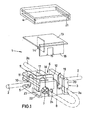
- the device for generating a vein splice i.e. for the electrically conductive connection of an initially continuous core 2 with a core 2a to be spliced, in the example shown consists of an essentially rectangular housing 3 with a housing cover 4.
- the housing 3 has two channels 5 at right angles to one another for the wire 2 and 6 for the wire 2a and an additional channel 7 which ends in the housing 3 and runs parallel to the channel 6 and into which the free end (designated 8 in FIG. 1) the wire 2a can be inserted.
- a cutting / clamping element 9 engages, which is equipped with contact cutting edges for penetrating the insulation of the wires 2 and 2a.
- the contact point for the initially continuous wire 2 is labeled 10.
- the contact point for the free end 8 of the wire 2a with 11 and the second contact point for the wire 2a after return and insertion into the channel 6 is finally designated 12.
- 3 guide slots are provided in the housing for cutting knives 14, 15 and 16 shown on a separate carrier plate 13 in FIG. 1, these guide slots being designated 17, 18 and 19. These guide slots 17-19 are arranged perpendicular to the channels 5, 6 and 7.
- the support member 13 for the cutting knife 14-16 can be, for example, the claw of a pair of pliers, not shown, or an integral part of the cover 4, so that the cutting movement is exerted when the cover 4 is pressed onto the housing 3.
- a snap connection between the housing 3 and cover 4 is provided, which in the example shown are composed of locking grooves 20 in the housing 3 and locking cams 21 in the cover 4.
- the housing 3 also has engaging grooves 22 for engaging a press tool, not shown.
- the pliers which can be equipped with the cutting knives, can also be designed in a fork-like manner in order to be able to engage in these grooves 22. If necessary, after inserting the cable wires 2 and 2a, both the contacting, i.e. the cutting / clamping element 9 is pressed in, as is the subsequent separation of the free end 8 or the part of the continuous cable core 2 which is no longer required by inserting the cutting knives 14-16 into the grooves 17-19 and then pressing the cover 4 on.
- a lock 23 is provided on the channel 7, which there consists of plastic lamellae which, after insertion of the free end 8 into this channel, holds this free end there without the invention being specific to this Design of locking would be limited.
- At least a receiving bore 24 is provided on the housing 3 for receiving a ratchet pin 25 of an adjacent housing 3 so that the devices can be fixed to one another line by line.
- This plug connection results in particular in connection with FIG. 2.
- a continuous cable core 2 is exposed from an existing cable 26, the right-hand side of which is to be spliced off at 26 ', and inserted into the continuous channel 5.
- the new cable is labeled 27, the new cable spliced with 2a. This is first inserted with its free end 8 into the housing 3, namely there in the channel 7.
- the substantially L-shaped cutting / clamping element 9 is now pushed on, so that the continuous wire 2 is connected to the free end 8 of the wire 2a in an electrically conductive manner.
- the wire 2a to be spliced is placed in a loop and is returned through the housing 3, as shown in FIG. 4, through the continuous channel 6 running parallel to channel 7. Clamping element 9 pressed from above that an electrically conductive connection is made. In this state, the wire 2 a is double electrically connected to the wire 2 that is still continuous.
- the described exemplary embodiment of the invention can be modified in many ways without departing from the basic idea.
- the invention is not limited to the special spatial arrangement of the channels in the device.
- Other angular parallelism or the like can also be provided here. This also applies to the design of the cutting / contact element as well as the separating knife 14-16 and / or the connection cover / housing.
Description
Die Erfindung richtet sich auf eine Vorrichtung zur Erzeugung eines Aderspleißes, insbesondere von Adern von Telefonkabeln, mit einem die Leiter der einzelnen Andern elektrisch verbindenden Schneid/Klemmelement mit einem die Verbindungsstelle umgebende Gehäuse, wobei das Gehäuse mit mindestens zwei den Durchgang von Adern ermöglichenden Kanälen versehen ist, wobei die Kanäle im wesentlichen im rechten Winkel zueinander angeordnet und mit dem gemeinsamen elektrisch leitenden Schneid/ Klemmelement zur isolierungsfreien elektrisch leitenden Verbindung der in die Kanäle eingelegten Kabeladern versehen sind.The invention is directed to a device for producing a wire splice, in particular wires of telephone cables, with a cutting / clamping element electrically connecting the conductors of the individual others with a housing surrounding the connection point, the housing being provided with at least two channels allowing the passage of wires is, wherein the channels are arranged substantially at right angles to each other and are provided with the common electrically conductive cutting / clamping element for insulation-free electrically conductive connection of the cable cores inserted into the channels.
Eine solche Vorrichtung ist beispielsweise aus der DE-B-1 212 180 bekannt, welche mehrere, parallel zueinander verlaufende, nebeneinander angeordnete Kanäle zur Aufnahme von miteinander zu verbindenden isolierten elektrischen Leitungen aufweist, wobei quer zur Längsrichtung der Kanälle ein als Schneid/Klemmelement ausgebildeter Verbinder mit einer der Anzahl der Kanäle entsprechenden Anzhal von Schlitzen zur isolierungsfreien Kontaktierung der Leitungen einsetzbar ist. Eine ähnliche Lösung zeigt die DE-B-1 257 921, bei der ebenfalls für jede Leitung ein Aufnahmekanal vorgesehen ist.Such a device is known, for example, from DE-B-1 212 180, which has a plurality of parallel, mutually adjacent channels for receiving insulated electrical lines to be connected, a connector designed as a cutting / clamping element transverse to the longitudinal direction of the channels can be used with a number of slots corresponding to the number of channels for insulation-free contacting of the lines. A similar solution is shown in DE-B-1 257 921, in which a receiving channel is also provided for each line.
Ferner ist aus der DE-A-2 405 418 eine Anordnung bekannt, bei der wenigstens ein Aufnahmekanal rechtwinkling zu den übrigen Kanälen angeordnet ist, was bei bestimmten Einsatzfällen aus Platzgründen von Vorteil sein kann. Darüber hinaus zeigt auch die US-A=3 718 888 eine gattungsgemäße Vorrichtung, bei der insbesondere einseitig ge schlossene, parallel angeordneter Aufnahmekanäle zur Aufnahme von miteinander zu verbindenden Leitungsenden vorgesehen sind.Furthermore, an arrangement is known from DE-A-2 405 418 in which at least one receiving channel is arranged at right angles to the other channels, which can be advantageous in certain applications for reasons of space. In addition, the US-A = 3 718 888 shows a generic device in which in particular one-sided closed, parallel receiving channels are provided for receiving line ends to be connected.
Gemeinsam ist den bekannten Lösungen, daß eine unterbrechungsfreie Verbindung der Leitungen auch unter Betrieb möglich ist. Soll jedoch zur Erzeugung eines Aderspleißes eine neue Ader unterbrechungsfrei unter Betrieb an eine durchlaufende Ader angeschlossen und die Durchlaufende Ader in ihrem wegfallenden Teil anschließend entfernt werden, so ist die Handhabung bei den bekannten Lösungen schwierig, insbesondere dann, wenn in der Umgebung des Aderspleißes noch eine Vielzahl anderer Adern angeordnet ist und somit nur ein geringer Montageraum zu Verfügung steht. Es ist dann nämlich notwendig, die einzuspleißende Ader bereits vor der Einführung in die Vorrichtung exakt auf die Endlänge einzukürzen und dann in den zugeordneten Aufnahmekanal einzuführen, was im Einzelfall schwierig sein kann und insbesondere dazu führen kann, daß die einzuspleißende Ader nicht weit genug in den Aufnahmekanal eingeführt wird, der Folge, daß dann anschließend keine Konbtaktierung erfolgt.Common to the known solutions is that an uninterrupted connection of the lines is also possible during operation. However, if a new wire is to be connected without interruption to a continuous wire during operation in order to produce a wire splice, and the missing wire in its omitted part is then to be removed, handling with the known solutions is difficult, especially if there is still one in the vicinity of the wire splice A large number of other wires is arranged and therefore only a small installation space is available. It is then necessary to shorten the wire to be spliced exactly to the final length before inserting it into the device and then insert it into the assigned receiving channel, which can be difficult in individual cases and in particular can lead to the wire not to be spliced far enough into the Recording channel is introduced, the consequence that then no contact is made.
Aufgabe der Erfindung ist die Schaffung einer Lösung, mit der insbesondere für Paare von Adern unterbrechungsfreies Einspleißen unter Betrieb möglich ist, wobei das Einspleißen leicht handhabbar und eine sichere Kontaktierung der einzuspleißenden Ader gewährleistet sein soll.The object of the invention is to provide a solution which enables uninterrupted splicing in operation, in particular for pairs of wires, the splicing being easy to handle and ensuring reliable contacting of the wire to be spliced in.
Bei einer Vorrichtung der eingangs bezeichneten Art wird diese Aufgabe gemäß de Erfindung dadurch gelöst, daß neben den beiden Durchgangskanälen noch wenigstens ein zu einem der Kanäle paralleler, in der Vorrichtung endender Kanal zum stumpfen Einführen eines freien Endes einer Ader vorgesehen ist, wobei das Schneid/ Klemmelement auch bereichsweise in diesen Kanal eingreifend angeordnet ist.In a device of the type described in the introduction, this object is achieved according to the invention in that, in addition to the two through channels, at least one channel parallel to one of the channels and ending in the device is provided for the blunt insertion of a free end of a wire, the cutting / Clamping element is also arranged in areas engaging in this channel.
Mit der Erfindung ist auf besonders leicht handhabbare Weise ein völlig unterbrechungsfreies Einspleißen eines neuen Kabels möglich, wobei gleichzeitig eine sichere Kontaktierung des eingespleißten Kabels gewährleistet ist. Eine durchlaufende Ader wird zunächst in einen Kanal der Vorrichtung eingelegt, während die einzuspleißende Ader mit ihrem freien Ende in den in der Vorrichtung endenden Kanal eingeführt wird. Durch die dann über das Schneid/Klemmelement erfolgende abisolierungsfreie elektrisch leitende Verbindung wird die einzuspleißende Ader unterbrechungsfrei mit der durchlaufenden Ader verbunden. Anschließend wird die vorarretierte, einzuspleißende Ader schlaufenförmig in den noch nicht belegten Durchgangskanal eingelegt" und vom Schneid/Klemmelement kontaktiert, derart, daß eine Einkürzung auf die gewünschte Einbaulänge möglich ist. Die durchlaufende Ader kann dann in ihrem wegfallenden Teil un die einzuspleißende Ader in ihrem schlaufenförmigen Teil entfernt werden, ohne daß während des Betriebes eine Unterbrechung erfolgt ist.With the invention, a completely uninterrupted splicing of a new cable is possible in a particularly easy-to-use manner, while at the same time a reliable contacting of the spliced-in cable is ensured. A continuous wire is first inserted into a channel of the device, while the wire to be spliced is inserted with its free end into the channel ending in the device. Because of the insulation-free, electrically conductive connection which then takes place via the cutting / clamping element, the wire to be spliced is connected without interruption to the continuous wire. Subsequently, the pre-arrested, spliced-in wire is inserted in a loop-like manner into the through channel not yet occupied and contacted by the cutting / clamping element in such a way that it can be shortened to the desired installation length loop-shaped part can be removed without an interruption taking place during operation.
In Ausgestaltung sieht die Erfindung vor, daß die Kontaktstelle im gemeinsamen Schneid/ Klemmelement nach Kontaktieren der in die Kanäle eingelegten Kabeladern als den Durchgangskanal nach oben offene, das nachträgliche Einlegen einer Kabelader ermöglichende Schneidklinge ausgebildet ist. Diese Ausgestaltung ermöglicht eine besonders einfache Handhabung.In an embodiment, the invention provides that the contact point in the common cutting / clamping element, after contacting the cable wires inserted in the channels, is designed as an upwardly open cutting blade which enables the subsequent insertion of a cable wire. This configuration enables particularly simple handling.
Die Erfindung sieht auch vor, daß senkrecht zu den Kanälen in den Durchgangsbereichen der Kabeladern Führungen zum Eingriff von Schneidmessern vorgesehen sind.The invention also provides that guides for engaging cutting knives are provided perpendicular to the channels in the passage areas of the cable wires.
Das unterbrechungsfreie Einspleißen und das Einkürzen kann dann wie folgt vorgenommen werden:The uninterrupted splicing and shortening can then be carried out as follows:
Zunächst wird die durchlaufende Ader, wie oben beschrieben, in einen Kanal eingelegt. Die einzuspleißende Ader wird in den stumpfen Kanal mit ihrem freien Ende eingeführt, und dann unter Bildung einer Schlaufe durch die Vorrichtung in den anderen Durchgangskanal eingelegt. Das Schneid/Klemmelement kontaktiert dabei zunächst die durchlaufende Ader und zweifach die einzuspleißende Ader durch deren Schlaufenbildung.First, the continuous wire is inserted into a channel as described above. The free end of the wire to be spliced is inserted into the blunt channel and then inserted through the device into the other through-channel, forming a loop. The cutting / clamping element first contacts the continuous wire and twice the wire to be spliced through its loop formation.
Zum Einkürzen werden in den senkrecht zu den Kanälen angeordneten Führungen Schneidmesser eingebracht, die dann sowohl die alte Ader abtrennen als auch den schlaufenbilden Bereich der einzuspleißenden Ader, ohne daß während des Gesamtvorganges eine Unterbrechung de elektrischen Leitung erfolgt wäre.To shorten them, cutting knives are inserted in the guides arranged perpendicular to the channels, which then cut off both the old wire and form the loop Area of the wire to be spliced in without the electrical line being interrupted during the entire process.
Die Erfindung sieht auch vor, daß die Schneidmesser in einem gesonderten Rauteil angeordnet sind. Dies gesonderte Bauteil kann beispielsweise an einer Druckplatte einer Zange angeordnet sein. Zweckmäßig kann es aber auch sein, die Schneidmesser direkt im Abschlußdeckel der Vorrichtung vorzusehen, so daß beim Aufbringen des Deckels der Schneidvorgang ausgeführt wird.The invention also provides that the cutting knives are arranged in a separate rough part. This separate component can, for example, be arranged on a pressure plate of a pair of pliers. However, it can also be expedient to provide the cutting knives directly in the end cover of the device, so that the cutting process is carried out when the cover is applied.
Nach der Erfindung ist das Gehäuse und der Abschlußdeckel mit jeweils korrespondierenden Elementen einer Schnappverbindung ausgerüstet, z.B. können randseitig im Gehäuse Nuten vorgesehen sein, di von entsprechenden Rastwülsten im Inneren des Deckels übergriffen werden.According to the invention, the housing and the end cover are each equipped with corresponding elements of a snap connection, e.g. Grooves can be provided on the edge side in the housing, which are overlapped by corresponding locking beads in the interior of the cover.
Um die Montage zu vereinfachen - es handelt sich bei der Vorrichtung in vielen Anwendungsfällen um ein vergleichsweise sehr kleines Bauteil - sieht die Erfindung auch vor, daß das Gehäuse mit Eingriffsnuten zum Eingriff eines Preßwerkzeuges zur Ausübung der Eingriffsbewegung des Schneid/Klemmelementes und/oder der Schneidmesser und/oder Rastverbindung zwischen Deckel und Gehäuse ausgerüstet ist.In order to simplify assembly - the device is a comparatively very small component in many applications - the invention also provides that the housing with engagement grooves for engaging a pressing tool to carry out the engagement movement of the cutting / clamping element and / or the cutting knife and / or snap connection between cover and housing is equipped.
Zweckmäßig kann es sein, wenn wenigstens im Bereich des im Gehäuse endenden Kanales eine Arretierungseinrichtung zum zeitweisen Festhalten der eingeführten Kabelader vorgesehen ist. Diese Arretierungseinrichtung kann beispielsweise durch entsprechende Laschen in der Einführungsöffnung gebildet sein, oder aber durch einen angeformten Klemmhaken hinter den die eingeführte Ader geklemmt werden kann.It may be expedient if, at least in the region of the channel ending in the housing, a locking device is provided for temporarily holding the inserted cable core. This locking device can be formed, for example, by corresponding tabs in the insertion opening, or else by a molded-in clamping hook behind which the inserted wire can be clamped.
Schließlich sieht die Erfindung noch vor, daß das Gehäuse an wenigstens einer Seite mit einer Aufnahmebohrung und an der dieser Aufnahmebohrung gegenüberliegenden Seite mit einem Klinkenstift zum Eingriff in die Aufnahmebohrung eines benachbarten Gehäuses ausgerüstet ist, so daß eine Vielzahl von Vorrichtung im Spleiß zu Leisten zusammensteckbar ist.Finally, the invention also provides that the housing is equipped on at least one side with a receiving bore and on the side opposite this receiving bore with a latch pin for engaging in the receiving bore of an adjacent housing, so that a plurality of devices can be plugged together into strips .
Die Erfindung ist nachstehend anhand der Zeichnung beispielsweise näher erläutert. Diese zeigt in
- Fig. 1 eine Explosionsdarstellung der Vorrichtung, in
- Fig. 2 eine Zeile von zusammengeklebten Vorrichtungen,
- Fig. 3 eine Einbausituation beim unterbrechungsfreien Einspleißen sowie in
- Fig. 4 die Einbausituation beim nachfolgenden Einkürzen.
- Fig. 1 is an exploded view of the device, in
- 2 shows a line of devices glued together,
- Fig. 3 shows an installation situation with uninterrupted splicing and in
- Fig. 4 shows the installation situation in the subsequent shortening.
Die in den Figuren allgemein mit 1 bezeichnete Vorrichtung zur Erzeugung eines Aderspleißes, d.h. zur elektrisch leitenden Verbindung einer zunächst durchlaufenden Ader 2 mit einer einzuspleißenden Ader 2a, besteht im dargestellten Beispiel aus einem im wesentlichen rechteckigen Gehäuse 3 mit einem Gehäusedeckel 4.The device for generating a vein splice, generally designated 1 in the figures, i.e. for the electrically conductive connection of an initially
Das Gehäuse 3 weist zwei im rechten Winkel zueinanderstehende Kanäle 5 für die Ader 2 und 6 für die Ader 2a auf sowie einen zum Kanal 6 parallelen im Gehäuse 3 endenden Zusatzkanal 7, in den stumpf das freie Ende (in Fig. 1 mit 8 bezeichnet) der Ader 2a eingeschoben werden kann.The
In die Kanäle 5, 6 und 7 greift bereichsweise ein Schneid/Klemmelement 9 ein, welches mit Kontaktschneiden ausgerüstet ist zum Durchdringen der Isolierung der Adern 2 bzw. 2a. Die Kontaktstelle für die zunächst durchgehende Ader 2 ist mit 10 benzeichnet. Die Kontaktstelle für das freie Ende 8 der Ader 2a mit 11 und die zweite Kontaktstelle für die Ader 2a nach Rückführung und Einlegen in den Kanal 6 ist schließlich mit 12 bezeichnet.In
Wie sich insbesondere aus Fig. 1 ergibt, sind in Gehäuse 3 Führungsschlitze für in der Fig. 1 an einer gesonderten Trägerplatte 13 dargestellte Schneidmesser 14, 15 und 16 vorgesehen, wobei diese Führungsschlitze mit 17, 18 und 19 bezeichnet sind. Diese Führungsschlitzte 17-19 sind senkrecht zu den Kanälen 5, 6 und 7 angeordnet. Das Tragelement 13 für die Schneidmesser 14-16 kan beispielsweise die Klaue einer nicht näher dargestellten Zange sein, oder aber integraler Bestandteil des Deckels 4, so daß die Schnittbewegung bei Aufdrücken des Deckels 4 auf das Gehäuse 3 ausgeübt wird.As can be seen in particular from FIG. 1, 3 guide slots are provided in the housing for
In der Fig. 1 ist noch dargestellt, daß eine Schnappverbindung zwischen Gehäuse 3 und Deckel 4 vorgesehen ist, die sich im dargestellten Beispiel aus Rastnuten 20 im Gehäuse 3 und Rastnocken 21 im Deckel 4 zusammensetzen. Schließlich weist das Gehäuse 3 auch noch Eingriffsnuten 22 auf zum Eingriff eines nicht näher dargestellten Preßwerkzeuges. So kann beispielsweise die Zange, die mit den Schneidmessern ausrüstbar ist, auch entsprechend gabelförmig ausgebildet sein, um in diese Nuten 22 eingreifen zu können. Gegebenenfalls kann nach Einlegen der Kabeladern 2 und 2a dann in einem Arbeitsgang sowohl die Kontaktierung, d.h. das Einpressen des Schneid/Klemmelementes 9 erfolgen, wie das nachfolgende Abtrennen des freien Endes 8 bzw. des nicht mehr benötigten Teiles der durchlaufenden Kabelader 2 durch Einführen der Schneidmesser 14-16 in die Nuten 17-19 und nachfolgendem Aufpressen des Deckels 4.In Fig. 1 it is also shown that a snap connection between the
Für die Montage kann es in der Praxis nützlich sein, Halteeinrichtungen für die eingelegten Adern vorzusehen. Insbesondere zur Festlegung des freien Endes 8 der einzuspleißenden Ader 2a ist am Kanal 7 eine Arretierung 23 vorgesehen, die dort aus Kunststofflamellen besteht, die nach-Einführen des freien Endes 8 in diiesen Kanal dieses freie Ende dort hält, ohne daß die Erfindung auf diese spezielle Gestaltungsform der Arretierung beschränkt wäre.In practice, it may be useful for assembly to provide holding devices for the inserted wires. In particular for fixing the
Schließlich ist am Gehäuse 3 noch wenigtens eine Aufnahmebohrung 24 zur Aufnahme eines Klinkenstiftes 25 eines benachbarten Gehäuses 3 vorgesehen, um so die Vorrichtungen zeilenweise aneinander festlegen zu können. Diese Steckverbindung ergibt sich insbesondere auch in Verbindung mit Fig. 2.Finally, at least a receiving
Die Wirkungsweise der Vorrichtung sei in Verbindung mit den Fig. 3 und 4 nochmals kurz wie folgt erläutert:The operation of the device is in Ver Binding with Figures 3 and 4 again briefly explained as follows:
Aus einem vorhandenen Kabel 26, dessen rechte abzuspleißende Seite mit 26' bezeichnet ist, wird eine durchgehende Kabelader 2 freigelegt und in den durchlaufenden Kanal 5 eingelegt. Das neue Kabel ist mit 27 bezeichnet, die neue einzuspleißende Kabelader mit 2a. Diese wird zunächst mit ihrem freien Ende 8 in das Gehäuse 3, und zwar dort in den Kanal 7, eingeführt. Das im wesentlichen L-förmige Schneid/Klemmelement 9 wird nunmehr aufgeschoben, so daß die durchlaufende Ader 2 mit dem freien Ende 8 der Ader 2a elektrisch leitend verbunden ist.A
Nunmehr wird die einzuspleißende Ader 2a in eine Schlaufe gelegt und so durch das Gehäuse 3 zurückgeführt, wie dies in Fig. 4 dargestellt ist, und zwar durch den parallel zu Kanal 7 verlaufenden durchgehenden Kanal 6. Dabei wird die Ader 2a so mit dem Schneid/Klemmelement 9 von oben verpreßt, daß eine elektrisch leitende Verbindung hergestellt wird. Die Ader 2a ist in diesem Zustand 2-fach elektrisch leitend mit der zunächst noch durchgehenden Ader 2 verbunden.Now the
Werden nun die Schneidmesser 14-16 von oben in die entsprechenden Kanäle 17-19 eingeführt, so ergibt sich bei der durchgehenden Ader 2 eine Schnittstelle 28, während die Schlaufe der Ader 2a durch zwei Schnittstellen 29 und 30 abgetrennt, d.h. eingekürzt wird. Während des gesamten Vorganges bleibt die elektrisch leitende Verbindung immer aufrechterhalten.If the cutting knives 14-16 are now inserted into the corresponding channels 17-19 from above, an
Natürlich ist das beschreibene Ausführungsbeispiel der Erfindung noch in vielfacher Hinsicht abzuändern ohne den Grundgedanken zu verlassen. So its die Erfindung nicht auf die spezielle räumliche Anordnung der Kanäle in der Vorrichtung beschränkt. Hier können auch andere Winkelparallelitäten od. dgl. vorgesehen sein. Dies gilt auch für die Gestaltung des Schneid/ Kontaktelementes ebenso wie der Trennmesser 14-16 und/oder der Verbindung Deckel/Gehäuse.Of course, the described exemplary embodiment of the invention can be modified in many ways without departing from the basic idea. Thus, the invention is not limited to the special spatial arrangement of the channels in the device. Other angular parallelism or the like can also be provided here. This also applies to the design of the cutting / contact element as well as the separating knife 14-16 and / or the connection cover / housing.
Claims (9)
Applications Claiming Priority (2)
| Application Number | Priority Date | Filing Date | Title |
|---|---|---|---|
| DE8433159U DE8433159U1 (en) | 1984-11-13 | 1984-11-13 | Device for creating a wire splice |
| DE8433159U | 1984-11-13 |
Publications (3)
| Publication Number | Publication Date |
|---|---|
| EP0182012A2 EP0182012A2 (en) | 1986-05-28 |
| EP0182012A3 EP0182012A3 (en) | 1989-03-15 |
| EP0182012B1 true EP0182012B1 (en) | 1990-06-20 |
Family
ID=6772638
Family Applications (1)
| Application Number | Title | Priority Date | Filing Date |
|---|---|---|---|
| EP85110494A Expired - Lifetime EP0182012B1 (en) | 1984-11-13 | 1985-08-21 | Device for producing a conductor splice |
Country Status (4)
| Country | Link |
|---|---|
| US (1) | US4725247A (en) |
| EP (1) | EP0182012B1 (en) |
| DE (2) | DE8433159U1 (en) |
| ES (1) | ES8702087A1 (en) |
Families Citing this family (7)
| Publication number | Priority date | Publication date | Assignee | Title |
|---|---|---|---|---|
| CA2009282C (en) * | 1989-02-06 | 2001-01-23 | Paul Lindsay Rishworth | Multi conductor electrical cable connector |
| US5586905A (en) * | 1993-11-01 | 1996-12-24 | Molex Incorporated | Insulation displacement electrical connector with improved strain relief |
| US5791933A (en) * | 1994-08-23 | 1998-08-11 | Sumitomo Wiring Systems, Ltd. | Wiring construction of electrical connection box |
| JPH08162177A (en) * | 1994-12-05 | 1996-06-21 | Yazaki Corp | Pressure contact method of wire to pressure contact connector and pressure contact connector |
| FR2819977B1 (en) * | 2001-01-23 | 2003-04-11 | Sofanou Sa | SUPPORT AND FIXING PART OF AN ELECTRICAL COMPONENT |
| US7186132B2 (en) | 2005-05-31 | 2007-03-06 | Raul Quintanilla | Electrical and electronic connector with blade closed by lever |
| JP7265458B2 (en) * | 2019-09-26 | 2023-04-26 | 日本航空電子工業株式会社 | Connector and connection method |
Family Cites Families (12)
| Publication number | Priority date | Publication date | Assignee | Title |
|---|---|---|---|---|
| US1290153A (en) * | 1918-03-30 | 1919-01-07 | Joseph Fitzpatrick | Wire-tapper. |
| US1488636A (en) * | 1920-05-24 | 1924-04-01 | Geiser John Albert | Wire connecter |
| US2469397A (en) * | 1945-11-14 | 1949-05-10 | Melvin E Mezek | Electrical connector |
| US2928066A (en) * | 1956-11-28 | 1960-03-08 | Gordon James | Electrical terminal block |
| NL129681C (en) * | 1959-03-19 | |||
| US3718888A (en) * | 1971-01-04 | 1973-02-27 | Bell Telephone Labor Inc | Universal connector for cable conductors |
| CA1001250A (en) * | 1973-02-02 | 1976-12-07 | Thomas J. Antolak | Solderless electrical contact element assembly, receptacle and applicator |
| NL155989B (en) * | 1973-12-19 | 1978-02-15 | Amp Inc | ELECTRICAL CONNECTOR WITH INSULATION CUTTING SLOTS. |
| US4326767A (en) * | 1979-03-12 | 1982-04-27 | Minnesota Mining And Manufacturing Company | Wire cutting electrical connector |
| US4232927A (en) * | 1979-03-16 | 1980-11-11 | E. I. Du Pont De Nemours And Company | Electrical connector |
| US4364622A (en) * | 1980-05-09 | 1982-12-21 | Minnesota Mining And Manufacturing Company | Connector for flat cable |
| US4441779A (en) * | 1980-12-31 | 1984-04-10 | E. I. Du Pont De Nemours & Company | Contact device for a multiconductor cable |
-
1984
- 1984-11-13 DE DE8433159U patent/DE8433159U1/en not_active Expired
-
1985
- 1985-08-21 DE DE8585110494T patent/DE3578365D1/en not_active Expired - Fee Related
- 1985-08-21 EP EP85110494A patent/EP0182012B1/en not_active Expired - Lifetime
- 1985-09-05 ES ES546732A patent/ES8702087A1/en not_active Expired
-
1987
- 1987-06-08 US US07/059,234 patent/US4725247A/en not_active Expired - Fee Related
Also Published As
| Publication number | Publication date |
|---|---|
| ES8702087A1 (en) | 1986-12-01 |
| EP0182012A2 (en) | 1986-05-28 |
| EP0182012A3 (en) | 1989-03-15 |
| DE8433159U1 (en) | 1985-02-07 |
| ES546732A0 (en) | 1986-12-01 |
| DE3578365D1 (en) | 1990-07-26 |
| US4725247A (en) | 1988-02-16 |
Similar Documents
| Publication | Publication Date | Title |
|---|---|---|
| DE3711675C2 (en) | ||
| DE2314330C2 (en) | Electrical connector | |
| EP0196495B1 (en) | Pliers | |
| DE2443476C2 (en) | Electrical connector | |
| DE4437022C1 (en) | Connector | |
| EP0244347B1 (en) | Connection block for cable cores, particularly those of telephone cables | |
| DE3239708C2 (en) | ||
| EP0595234A1 (en) | Cable connector for multicore cables | |
| DE2338056B2 (en) | Electrical connector | |
| DE602005004414T2 (en) | DEVICE FOR ELECTRIC CONNECTION OF DISCONTINUOUS LADDER | |
| DE19735835A1 (en) | Electrical lead wire terminal clamp | |
| DE3009675C2 (en) | ||
| DE2740962A1 (en) | DEVICE FOR ASSEMBLING CABLES IN THE CONTACT ELEMENTS OF AN ELECTRICAL CONNECTOR | |
| DE2948725A1 (en) | CONTACT ELEMENT FOR AN ELECTRICAL CONNECTOR | |
| DE2328505C2 (en) | Electrical connector for the electrical connection of at least two conductor wires | |
| EP0182012B1 (en) | Device for producing a conductor splice | |
| DE19838423C2 (en) | Ribbon cable connectors | |
| DE19903030C1 (en) | Device for stripping-free contacting of a flat cable | |
| DE2131769B2 (en) | Resilient electrical solderless connector - has conductor contact and support slits in different planes for clamping action | |
| DE4320539C2 (en) | Line wire connector | |
| DE19949386C2 (en) | Device connection box with cutting technology | |
| DE3108931A1 (en) | Terminal block | |
| DE1963313B2 (en) | Solderless terminal tag for bared wires - has spring fingers at one end with gripping hollows to hold two orthogonal wires | |
| DE19817433C2 (en) | Electrical connection unit | |
| DE3602812A1 (en) | ELECTRIC CONNECTOR |
Legal Events
| Date | Code | Title | Description |
|---|---|---|---|
| PUAI | Public reference made under article 153(3) epc to a published international application that has entered the european phase |
Free format text: ORIGINAL CODE: 0009012 |
|
| AK | Designated contracting states |
Kind code of ref document: A2 Designated state(s): DE FR GB IT SE |
|
| PUAL | Search report despatched |
Free format text: ORIGINAL CODE: 0009013 |
|
| AK | Designated contracting states |
Kind code of ref document: A3 Designated state(s): DE FR GB IT SE |
|
| 17P | Request for examination filed |
Effective date: 19890206 |
|
| 17Q | First examination report despatched |
Effective date: 19890728 |
|
| GRAA | (expected) grant |
Free format text: ORIGINAL CODE: 0009210 |
|
| AK | Designated contracting states |
Kind code of ref document: B1 Designated state(s): DE FR GB IT SE |
|
| REF | Corresponds to: |
Ref document number: 3578365 Country of ref document: DE Date of ref document: 19900726 |
|
| GBT | Gb: translation of ep patent filed (gb section 77(6)(a)/1977) | ||
| ITF | It: translation for a ep patent filed |
Owner name: MODIANO & ASSOCIATI S.R.L. |
|
| ET | Fr: translation filed | ||
| PLBE | No opposition filed within time limit |
Free format text: ORIGINAL CODE: 0009261 |
|
| STAA | Information on the status of an ep patent application or granted ep patent |
Free format text: STATUS: NO OPPOSITION FILED WITHIN TIME LIMIT |
|
| 26N | No opposition filed | ||
| ITTA | It: last paid annual fee | ||
| PGFP | Annual fee paid to national office [announced via postgrant information from national office to epo] |
Ref country code: SE Payment date: 19930802 Year of fee payment: 9 |
|
| PGFP | Annual fee paid to national office [announced via postgrant information from national office to epo] |
Ref country code: GB Payment date: 19930803 Year of fee payment: 9 |
|
| PGFP | Annual fee paid to national office [announced via postgrant information from national office to epo] |
Ref country code: FR Payment date: 19930813 Year of fee payment: 9 |
|
| PG25 | Lapsed in a contracting state [announced via postgrant information from national office to epo] |
Ref country code: GB Effective date: 19940821 |
|
| PG25 | Lapsed in a contracting state [announced via postgrant information from national office to epo] |
Ref country code: SE Effective date: 19940822 |
|
| EAL | Se: european patent in force in sweden |
Ref document number: 85110494.3 |
|
| GBPC | Gb: european patent ceased through non-payment of renewal fee |
Effective date: 19940821 |
|
| PG25 | Lapsed in a contracting state [announced via postgrant information from national office to epo] |
Ref country code: FR Effective date: 19950428 |
|
| EUG | Se: european patent has lapsed |
Ref document number: 85110494.3 |
|
| REG | Reference to a national code |
Ref country code: FR Ref legal event code: ST |
|
| PGFP | Annual fee paid to national office [announced via postgrant information from national office to epo] |
Ref country code: DE Payment date: 19980827 Year of fee payment: 14 |
|
| PG25 | Lapsed in a contracting state [announced via postgrant information from national office to epo] |
Ref country code: DE Free format text: LAPSE BECAUSE OF NON-PAYMENT OF DUE FEES Effective date: 20000601 |