EP0182012A2 - Device for producing a conductor splice - Google Patents
Device for producing a conductor splice Download PDFInfo
- Publication number
- EP0182012A2 EP0182012A2 EP85110494A EP85110494A EP0182012A2 EP 0182012 A2 EP0182012 A2 EP 0182012A2 EP 85110494 A EP85110494 A EP 85110494A EP 85110494 A EP85110494 A EP 85110494A EP 0182012 A2 EP0182012 A2 EP 0182012A2
- Authority
- EP
- European Patent Office
- Prior art keywords
- channels
- housing
- cutting
- wires
- wire
- Prior art date
- Legal status (The legal status is an assumption and is not a legal conclusion. Google has not performed a legal analysis and makes no representation as to the accuracy of the status listed.)
- Granted
Links
Images
Classifications
-
- H—ELECTRICITY
- H01—ELECTRIC ELEMENTS
- H01R—ELECTRICALLY-CONDUCTIVE CONNECTIONS; STRUCTURAL ASSOCIATIONS OF A PLURALITY OF MUTUALLY-INSULATED ELECTRICAL CONNECTING ELEMENTS; COUPLING DEVICES; CURRENT COLLECTORS
- H01R4/00—Electrically-conductive connections between two or more conductive members in direct contact, i.e. touching one another; Means for effecting or maintaining such contact; Electrically-conductive connections having two or more spaced connecting locations for conductors and using contact members penetrating insulation
- H01R4/24—Connections using contact members penetrating or cutting insulation or cable strands
- H01R4/2416—Connections using contact members penetrating or cutting insulation or cable strands the contact members having insulation-cutting edges, e.g. of tuning fork type
- H01R4/242—Connections using contact members penetrating or cutting insulation or cable strands the contact members having insulation-cutting edges, e.g. of tuning fork type the contact members being plates having a single slot
- H01R4/2425—Flat plates, e.g. multi-layered flat plates
- H01R4/2429—Flat plates, e.g. multi-layered flat plates mounted in an insulating base
-
- H—ELECTRICITY
- H01—ELECTRIC ELEMENTS
- H01R—ELECTRICALLY-CONDUCTIVE CONNECTIONS; STRUCTURAL ASSOCIATIONS OF A PLURALITY OF MUTUALLY-INSULATED ELECTRICAL CONNECTING ELEMENTS; COUPLING DEVICES; CURRENT COLLECTORS
- H01R4/00—Electrically-conductive connections between two or more conductive members in direct contact, i.e. touching one another; Means for effecting or maintaining such contact; Electrically-conductive connections having two or more spaced connecting locations for conductors and using contact members penetrating insulation
- H01R4/24—Connections using contact members penetrating or cutting insulation or cable strands
- H01R4/2416—Connections using contact members penetrating or cutting insulation or cable strands the contact members having insulation-cutting edges, e.g. of tuning fork type
- H01R4/2445—Connections using contact members penetrating or cutting insulation or cable strands the contact members having insulation-cutting edges, e.g. of tuning fork type the contact members having additional means acting on the insulation or the wire, e.g. additional insulation penetrating means, strain relief means or wire cutting knives
- H01R4/245—Connections using contact members penetrating or cutting insulation or cable strands the contact members having insulation-cutting edges, e.g. of tuning fork type the contact members having additional means acting on the insulation or the wire, e.g. additional insulation penetrating means, strain relief means or wire cutting knives the additional means having two or more slotted flat portions
Definitions
- the invention is directed to a device for testing a wire splice, in particular wires of telephone cables, with an element electrically connecting the conductors of the individual wires and a sheath surrounding the connecting point.
- wire connecting sleeves are known as simple connecting means, which consist of an inner contact part with inwardly projecting tips for penetrating the conductor insulation, a pressure part for easier deformability and an outer insulating part, e.g. a plastic sleeve.
- the ends of cable wires to be connected are inserted into these known wire connecting sleeves, the connecting sleeve is then pressed with a tool, so that the inner contact part penetrates the insulation of the inserted two cable ends and connects the conductors to one another in an electrically conductive manner.
- wire connection strips are also known, which are equipped with comb-like cutting / clamping elements, into which the cable wires to be connected are inserted and by pressing the housing parts, these strips are both electrically conductive which can also be shortened (for example DF-GM 82 20 212 by the applicant).
- the object of the invention is to provide a solution with which an uninterrupted splicing in operation is possible, in particular for pairs of wires, the device for remaining in the final splice being just as suitable as is the case with the cable core connecting sleeves.
- this object is achieved according to the invention in that the sheath or the housing is provided with at least two channels which allow the passage of wires, the channels having a common electrically conductive cutting / clamping element for stripping-free electrically conductive Connection of the cable wires inserted in the channels are provided.
- a continuous wire is first inserted into a channel of the device while the wire to be spliced is inserted into the other channel.
- the wire is designedsplskyende interruption of the connected to the passing through A.
- the trailing wire can then be removed in its omitted part without an interruption taking place during operation.
- the invention provides that the two channels are arranged essentially at right angles to one another within the device, in which case the cutting / clamping element is also expediently designed at right angles.
- the invention also provides that, in addition to the two through-channels, at least one channel parallel to one of the channels and ending in the device for blunt insertion of a free end of a wire is provided, the cutting / clamping element also being arranged to engage in this channel in some areas.
- the invention also provides that guides for the engagement of cutting knives are provided perpendicular to the channels in the through-quan regions of the cable cores.
- cutting knives are inserted in the guides arranged perpendicular to the channels, which then cut off both the old wire and the loop-forming area of the A to be spliced in without the electrical line being interrupted during the entire process.
- the invention also provides that the cutting knives are arranged in a separate component.
- This separate member may be arranged for example on a printing plate of a Zan- g e.
- the housing and the end cover are each equipped with corresponding elements of a snap connection, for. B. can be provided on the edge of the housing grooves, which are overlapped by corresponding locking beads inside the cover.
- the device In order to simplify assembly - the device is a comparatively very small component in many applications - the invention also provides that the housing with engagement grooves for engaging a pressing tool to carry out the engagement movement of the cutting / clamping element and / or the cutting knife and / or snap connection between cover and housing is equipped.
- a locking device is provided for temporarily holding the inserted cable core.
- This locking device can be formed, for example, by corresponding tabs in the insertion opening, or else by a molded-in clamping hook behind which the inserted wire can be clamped.
- the housing is equipped on at least one side with a receiving bore and on the opposite side of this receiving bore with a ratchet pin for engaging in the receiving bore of an adjacent housing, so that a lot number of devices in the splice can be plugged together into strips.
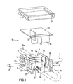
- the device generally designated 1 in the figures for producing a wire splice, ie for the electrically conductive connection of an initially continuous A of FIG. 2 to a wire 2a to be spliced, in the example shown consists of an essentially rectangular housing 3 with a housing cover 4.
- the housing 3 has two channels 5 at right angles to one another for the wire 2 and 6 for the wire 2a and an additional channel 7 which ends in the housing 3 and runs parallel to the channel 6 and into which the free end (designated 8 in FIG. 1) the wire 2a can be inserted.
- a cutting / clamping element 9 engages, which is equipped with contact cutting edges for penetrating the insulation of the wires 2 and 2a.
- the contact point for the initially continuous wire 2 is designated 10.
- the contact point for the free end 8 of the wire 2a with 11 and the second contact point for the wire 2a after return and insertion into the channel 6 is finally designated 12.
- 3 guide slots are provided in the housing for cutting knives 14, 15 and 16 shown on a separate carrier plate 13 in FIG. 1, these guide slots being designated 17, 18 and 19. These guide slots 17-19 are arranged perpendicular to the channels 5, 6 and 7.
- the support element 13 for the cutting knives 14-16 can, for example, be the claw of a pair of pliers (not shown in more detail) or an integral part of the cover 4, so that the cutting movement is exerted on the housing 3 when the cover 4 is pressed on.
- a snap connection between the housing 3 and cover 4 is provided, which in the example shown are composed of locking grooves 20 in the housing 3 and locking cams 21 in the cover 4.
- the housing 3 also has finger grooves 22 to engage a press tool, not shown.
- the pliers which can be equipped with the cutting blades, can also be designed in a fork-like manner in order to be able to engage in these grooves 22.
- both the contacting that is to say the pressing in of the cutting / clamping element 9, and the subsequent separation of the free end 8 or the part of the continuous cable core 2 which is no longer required by inserting the cutting knives can then take place in one work step 14 - 16 into the grooves 17 - 19 and then pressing on the cover 4.
- a lock 23 is at the channel 7 is provided, which there consists of plastic blades, which holds in this channel, this free E n-de therein after insertion of the free end 8, without the invention to this special form of locking would be limited.
- At least a receiving bore 24 is provided on the housing 3 for receiving a ratchet pin 25 of an adjacent housing 3 so that the devices can be fixed to one another line by line.
- This plug connection results in particular in connection with FIG. 2.
- the wire 2a to be spliced is placed in a loop and is returned through the housing 3, as shown in FIG. 4, through the continuous channel 6 running parallel to channel 7. Clamping element 9 pressed from above that an electrically conductive connection is made. In this state, the wire 2 a is double electrically connected to the wire 2 that is still continuous.
- the continuous core 2 has an interface 28, while the loop of the core 2a is separated, ie shortened, by two interfaces 29 and 30.
- the electrically conductive connection is always maintained throughout the entire process.
- the described embodiment of the invention can be modified in many ways without departing from the basic idea.
- the invention is not limited to the special spatial arrangement of the channels in the device.
- Other angular parallelism or the like can also be provided here. This also applies to the design of the cutting / contact element as well as the separating knife 14-16 and / or the connection cover / housing.
Abstract
Mit einer Vorrichtung zur Erzeugung eines Aderspleißes, insbesondere von Adern von Telefonkabeln, mit einem die Leiter der einzelnen Adern elektrisch verbindenden Element und einer die Verbindungsstelle umgebenden Umhüllung, soll eine Lösung geschaffen werden, mit der insbesondere für Paare von Adern ein unterbrechungsfreies Einspleißen unter Betrieb möglich ist, wobei die Vorrichtung zum Verbleib in dem endgültigen Spleiß ebenso geeignet ist, wie dies bei den Kabelverbindungshülsen der Fall ist. Dies wird dadurch erreicht, daß die Umhüllung bzw. das Gehäuse (3) mit wenigstens zwei den Durchgang von Adern (2, 2a) ermöglichenden Kanälen (5, 6) versehen ist, wobei die Kanäle (5, 6) mit einem gemeinsamen elektrisch leitenden Schneid/Klemmelement (9) zur abisolierungsfreien elektrisch leitenden Verbindung der in die Kanäle (5, 6) eingelegten Kabeladern (2, 2a) versehen sind.With a device for producing a wire splice, in particular wires of telephone cables, with an element electrically connecting the conductors of the individual wires and a sheath surrounding the connection point, a solution is to be created with which, particularly for pairs of wires, an uninterrupted splicing in during operation is possible , the device being suitable for remaining in the final splice, as is the case with the cable connecting sleeves. This is achieved in that the sheath or the housing (3) is provided with at least two channels (5, 6) which allow the passage of wires (2, 2a), the channels (5, 6) having a common electrically conductive one Cutting / clamping element (9) for stripping-free, electrically conductive connection of the cable cores (2, 2a) inserted in the channels (5, 6) are provided.
Description
Die Frfindung richtet sich auf eine Vorrichtung zur Przeugung eines Aderspleißes, insbesondere von Adern von Telefonkabeln, mit einem die Leiter der einzelnen Adern elektrisch verbindenden Element und einer die Verbindungsstel-Je umgebenden Umhüllung.The invention is directed to a device for testing a wire splice, in particular wires of telephone cables, with an element electrically connecting the conductors of the individual wires and a sheath surrounding the connecting point.
Es sind neben anderen bekannten Lösungen als einfache Verbindungsmittel sogenannte Aderverbindungshülsen bekannt, die aus einem inneren Kontaktteil mit nach Innen ragenden Spitzen zur Durchdringung der Leiterisolierung, aus einem Druckteil zur leichteren Verformbarkeit und aus einem äußeren Isolierteil, z.B. einer Kunststoffhülse, bestehen. In diese bekannte Aderverbindunashülsen werden die zu verbindenen Enden von Kabeladern eingeschoben, die Verbindunqshülse wird dann mit einem Werkzeug verpreßt, so daß das innere Kontaktteil die Isolierung der eingeführten beiden Kabelenden durchdringt und die Leiter elektrisch leitend miteinander verbindet.In addition to other known solutions, so-called wire connecting sleeves are known as simple connecting means, which consist of an inner contact part with inwardly projecting tips for penetrating the conductor insulation, a pressure part for easier deformability and an outer insulating part, e.g. a plastic sleeve. The ends of cable wires to be connected are inserted into these known wire connecting sleeves, the connecting sleeve is then pressed with a tool, so that the inner contact part penetrates the insulation of the inserted two cable ends and connects the conductors to one another in an electrically conductive manner.
Vermag diese zweckmäßige Aderverbindungshülse jeweils pur ein Paar von Adern zu verbinden, so sind auch sogenannte Aderverbindungsleisten bekannt, die mit kammartigen Schneid/Kleminelementen ausgerüstet sind, in die die zu verbindenen Kabeladern eingelegt und durch Verpressen der Gehäuseteile diese Leisten sowohl elektrisch leitend verbupden als auch eingekürzt werden (so z. R. DF-GM 82 20 212 der Anmelderin).If this expedient wire connection sleeve is able to connect a pair of wires, then so-called wire connection strips are also known, which are equipped with comb-like cutting / clamping elements, into which the cable wires to be connected are inserted and by pressing the housing parts, these strips are both electrically conductive which can also be shortened (for example DF-GM 82 20 212 by the applicant).
Beiden Verbindungsarten ist gemeinsam, daß bei der Spleißherstellung, z. B. bei Umschaltarbeiten, kurzzeitig der Betrieb unterbrochen werden muß, wenn das alte Kabel entfernt und das neue eingespleißt wird.Both types of connection have in common that in splicing, e.g. B. during switching work, the operation must be interrupted briefly when the old cable is removed and the new one is spliced in.
Aufgabe der Erfindung ist die Schaffung einer Lösung, mit der insbesondere für Paare von Adern ein unterbrechunqsfreies Einspleißen unter Betrieb möglich ist, wobei die Vorrichtung zum Verbleib in dem endgültigen Spleiß ebenso geeignet ist, wie dies bei den Kabeladerverbindungshülsen der Fall ist.The object of the invention is to provide a solution with which an uninterrupted splicing in operation is possible, in particular for pairs of wires, the device for remaining in the final splice being just as suitable as is the case with the cable core connecting sleeves.
Bei einer Vorrichtung der eingangs bezeichneten Art wird diese Aufgabe gemäß der Erfindung dadurch gelöst, daß die Umhüllung bzw. das Gehäuse mit wenigstens zwei den Durchgang von Adern ermöglichenden Kanälen versehen ist, wobei die Kanäle mit einem gemeinsamen elektrisch leitenden Schneid/Klemmelement zur abisolierungsfreien elektrisch leitenden Verbindung der in die Kanäle eingelegten Kabeladern versehen sind.In a device of the type mentioned at the outset, this object is achieved according to the invention in that the sheath or the housing is provided with at least two channels which allow the passage of wires, the channels having a common electrically conductive cutting / clamping element for stripping-free electrically conductive Connection of the cable wires inserted in the channels are provided.
Mit der Erfindüng ist das völlig unterbrechungsfreie rinspleißen eines neuen Kabels möglich. Eine durchlaufende Ader wird zunächst in einen Kanal der Vorrichtung eingelegt, während die einzuspleißende Ader in den anderen Kanal eingelegt wird. Durch die dann über das Schneid/Klemmelement erfolgende abisolierungsfreie elektrisch leitende Verbindung, wird die einzuspleißende Ader unterbrechungsfrei mit der durchlaufenden Ader verbunden. Die durchlaufende Ader kann dann in ihrem wegfallenden Teil entfernt werden, ohne daß während des Betriebes eine Unterbrechung erfolgt ist.With the invention, the completely uninterrupted splicing of a new cable is possible. A continuous wire is first inserted into a channel of the device while the wire to be spliced is inserted into the other channel. By then using the cutting / clamping element taking place abisolierungsfreie electrically conductive connection, the wire is einzuspleißende interruption of the connected to the passing through A. The trailing wire can then be removed in its omitted part without an interruption taking place during operation.
In Ausgestaltung sieht die Erfindung vor, daß die beiden Kanäle im wesentlichen im rechten Winkel zueinander innerhalb der Vorrichtung angeordnet sind, wobei in diesem Falle auch zweckmäßig das Schneid/Klemmelement rechtwinklig ausgeführt ist.In an embodiment, the invention provides that the two channels are arranged essentially at right angles to one another within the device, in which case the cutting / clamping element is also expediently designed at right angles.
Die Erfindung sieht auch vor, daß neben den beiden Durchgangskanälen noch wenigstens ein zu einem der Kanäle paralleler, in der Vorrichtung endender Kanal zum stumpfen Einführen eines freien Endes einer Ader vorgesehen ist, wobei das Schneid/Klemmelement auch bereichsweise in diesen Kanal eingreifend angeordnet ist.The invention also provides that, in addition to the two through-channels, at least one channel parallel to one of the channels and ending in the device for blunt insertion of a free end of a wire is provided, the cutting / clamping element also being arranged to engage in this channel in some areas.
In Verbindung mit dieser Lösung sieht die Erfindung auch vor, daß senkrecht zu den Kanälen in den Durchqanasbereichen der Kabeladern Führungen zum Eingriff von Schneidmessern vorgesehen sind.In connection with this solution, the invention also provides that guides for the engagement of cutting knives are provided perpendicular to the channels in the through-quan regions of the cable cores.
Das unterbrechungsfreie Einspleißen und das Finkürzen kann dann wie folgt vorgenommen werden:
- Zunächst wird die durchlaufende Ader, wie oben beschrieben, in einen Kanal eingelegt. Die einzuspleißende Ader wird in den stumpfen Kanal mit ihrem freien Ende eingeführt, und dann unter Bildung einer Schlaufe durch die Vorrichtung in den anderen Durchgangskanal eingelegt. Das Schneid/Klemmelement kontaktiert dabei zunächst die durchlaufende Ader und zweifach die einzuspleißende Ader durch deren Schlaufenbildung.
- First, the continuous wire is inserted into a channel as described above. The free end of the wire to be spliced is inserted into the blunt channel and then inserted through the device into the other through-channel, forming a loop. The cutting / clamping element first contacts the continuous wire and twice the wire to be spliced through its loop formation.
Zum Einkürzen werden in den senkrecht zu den Kanälen angeordneten Führungen Schneidmesser eingebracht, die dann sowohl die alte Ader abtrennen als auch den schlaufenbildenden Bereich der einzuspleißenden Ader, ohne daß während des Gesamtvorganges eine Unterbrechung der elektrischen Leitung erfolgt wäre.To shorten E, cutting knives are inserted in the guides arranged perpendicular to the channels, which then cut off both the old wire and the loop-forming area of the A to be spliced in without the electrical line being interrupted during the entire process.
Die Erfindung sieht auch vor, daß die Schneidmesser in einem gesonderten Bauteil angeordnet sind. Dies gesonderte Bauteil kann beispielsweise an einer Druckplatte einer Zan- ge angeordnet sein. Zweckmäßig kann es aber auch sein, die Schneidmesser direkt im Abschlußdeckel der Vorrichtung vorzusehen, so daß beim Aufbringen des Deckels der Schneidvorgang ausgeführt wird.The invention also provides that the cutting knives are arranged in a separate component. This separate member may be arranged for example on a printing plate of a Zan- g e. However, it can also be expedient to provide the cutting knives directly in the end cover of the device, so that the cutting process is carried out when the cover is applied.
Nach der Erfindung ist das Gehäuse und der Abschlußdeckel mit jeweils korrespondierenden Elementen einer Schnappverbindung ausgerüstet, z. B. können randseitig im Gehäuse Nuten vorgesehen sein, die von entsprechenden Rastwülsten im Inneren des Deckels übergriffen werden.According to the invention, the housing and the end cover are each equipped with corresponding elements of a snap connection, for. B. can be provided on the edge of the housing grooves, which are overlapped by corresponding locking beads inside the cover.
Um die Montage zu vereinfachen - es handelt sich bei der Vorrichtung in vielen Anwendungsfällen um ein vergleichsweise sehr kleines Bauteil - sieht die Erfindung auch vor, daß das Gehäuse mit Eingriffsnuten zum Eingriff eines Preßwerkzeuges zur Ausübung der Eingriffsbewegung des Schneid/ Klemmelementes und/oder der Schneidmesser und/oder Rastverbindung zwischen Deckel und Gehäuse ausgerüstet ist.In order to simplify assembly - the device is a comparatively very small component in many applications - the invention also provides that the housing with engagement grooves for engaging a pressing tool to carry out the engagement movement of the cutting / clamping element and / or the cutting knife and / or snap connection between cover and housing is equipped.
Zweckmäßig kann es sein, wenn wenigstens im Bereich des im Gehäuse endenden Kanales eine Arretierungseinrichtung zum zeitweisen Festhalten der eingeführten Kabelader voraesehen ist. Diese Arretierungseinrichtung kann beispielsweise durch entsprechende Laschen in der Einführungsöffnung gebildet sein, oder aber durch einen angeformten Klemmhaken hinter den die eingeführte Ader geklemmt werden kann.It may be expedient if, at least in the region of the channel ending in the housing, a locking device is provided for temporarily holding the inserted cable core. This locking device can be formed, for example, by corresponding tabs in the insertion opening, or else by a molded-in clamping hook behind which the inserted wire can be clamped.
Schließlich sieht die Erfindung noch vor, daß das Gehäuse an wenigstens einer Seite mit einer Aufnahmebohrung und an der dieser Aufnahmebohrung gegenüberliegenden Seite mit einem Klinkenstift zum Eingriff in die Aufnahmebohrung eines benachbarten Gehäuses ausgerüstet ist, so daß eine Vielzahl von Vorrichtungen im Spleiß zu Leisten zusammensteckbar ist.Finally, the invention provides that the housing is equipped on at least one side with a receiving bore and on the opposite side of this receiving bore with a ratchet pin for engaging in the receiving bore of an adjacent housing, so that a lot number of devices in the splice can be plugged together into strips.
Die Erfindung ist nachstehend anhand der Zeichnung beispielsweise näher erläutert. Diese zeigt in
- Fiq. 1 eine Explosionsdarstellung der Vorrichtung, in
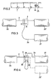
- Fig. 2 eine Zeile von zusammengeklebten Vorrichtungen,
- Fig. 3 eine Einbausituation beim unterbrechungsfreien Einspleißen sowie in
- Fig. 4 die Einbausituation beim nachfolgenden Einkürzen.
- Fiq. 1 is an exploded view of the device, in
- 2 shows a line of devices glued together,
- Fig. 3 shows an installation situation with uninterrupted splicing and in
- Fig. 4 shows the installation situation in the subsequent shortening.
Die in den Figuren allgemein mit 1 bezeichnete Vorrichtung zur Erzeugung eines Aderspleißes, d. h. zur elektrisch leitenden Verbindung einer zunächst durchlaufenden Ader 2 mit einer einzuspleißenden Ader 2a, besteht im dargestellten Beispiel aus einem im wesentlichen rechteckigen Gehäuse 3 mit einem Gehäusedeckel 4.The device generally designated 1 in the figures for producing a wire splice, ie for the electrically conductive connection of an initially continuous A of FIG. 2 to a
Das Gehäuse 3 weist zwei im rechten Winkel zueinanderstehende Kanäle 5 für die Ader 2 und 6 für die Ader 2a auf sowie einen zum Kanal 6 parallelen im Gehäuse 3 endenden Zusatzkanal 7, in den stumpf das freie Ende (in Fig. 1 mit 8 bezeichnet) der Ader 2a eingeschoben werden kann.The
In die Kanäle 5, 6 und 7 greift bereichsweise ein Schneid/ Klemmelement 9 ein, welches mit Kontaktschneiden ausgerüstet ist zum Durchdringen der Isolierung der Adern 2 bzw. 2a. Die Kontaktstelle für die zunächst durchgehende Ader 2 ist mit 10 bezeichnet. Die Kontaktstelle für das freie Ende 8 der Ader 2a mit 11 und die zweite Kontaktstelle für die Ader 2a nach Rückführung und Einlegen in den Kanal 6 ist schließlich mit 12 bezeichnet.In
Wie sich insbesondere aus Fig. 1 ergibt, sind im Gehäuse 3 Führungsschlitze für in der Fig. 1 an einer gesonderten Trägerplatte 13 dargestellte Schneidmesser 14, 15 und 16 vorgesehen, wobei diese Führungsschlitze mit 17, 18 und 19 bezeichnet sind. Diese Führungsschlitze 17 - 19 sind senkrecht zu den Kanälen 5, 6 und 7 angeordnet. Das Tragelement 13 für die Schneidmesser 14 - 16 kann beispielsweise die Klaue einer nicht näher dargestellten Zange sein, oder aber integraler Bestandteil des Deckels 4, so daß die Schnittbewegung bei Aufdrücken des Deckels 4 auf das Gehäuse 3 ausgeübt wird.As can be seen in particular from FIG. 1, 3 guide slots are provided in the housing for
In der Fig. 1 ist noch dargestellt, daß eine Schnappverbindung zwischen Gehäuse 3 und Deckel 4 vorgesehen ist, die sich im dargestellten Beispiel aus Rastnuten 20 im Gehäuse 3 und Rastnocken 21 im Deckel 4 zusammensetzen. Schließlich weist das Gehäuse 3 auch noch Fingriffsnuten 22 auf zum Eingriff eines nicht näher dargestellten Preßwerkzeuges. So kann beispielsweise die Zange, die mit den Schneidmessern ausrüstbar ist, auch entsprechend gabelförmig ausgebildet sein, um in diese Nuten 22 eingreifen zu können. Gegebenenfalls kann nach Einlegen der Kabeladern 2 und 2a dann in einem Arbeitsgang sowohl die Kontaktierung, d. h. das Einpressen des Schneid/Klemmelementes 9 erfolgen, wie das nachfolgende Abtrennen des freien Endes 8 bzw. des nicht mehr benötigten Teiles der durchlaufenden Kabelader 2 durch Einführen der Schneidmesser 14 - 16 in die Nuten 17 - 19 und nachfolgendem Aufpressen des Deckels 4.In Fig. 1 it is also shown that a snap connection between the
Für die Montage kann es in der Praxis nützlich sein, Halteeinrichtungen für die eingelegten Adern vorzusehen. Insbesondere zur Festlegung des freien Endes 8 der einzuspleißenden Ader 2a ist am Kanal 7 eine Arretierung 23 vorgesehen, die dort aus Kunststofflamellen besteht, die nach Einführen des freien Endes 8 in diesen Kanal dieses freie En-de dort hält, ohne daß die Erfindung auf diese spezielle Gestaltungsform der Arretierung beschränkt wäre.In practice, it may be useful for assembly to provide holding devices for the inserted wires. For determining in particular the
Schließlich ist am Gehäuse 3 noch wenigtens eine Aufnahmebohrung 24 zur Aufnahme eines Klinkenstiftes 25 eines benachbarten Gehäuses 3 vorgesehen, um so die Vorrichtungen zeilenweise aneinander festlegen zu können. Diese Steckverbindung ergibt sich insbesondere auch in Verbindung mit Fig. 2.Finally, at least a receiving
Die Wirkungsweise der Vorrichtung sei in Verbindung mit den Fig. 3 und 4 nochmals kurz wie folgt erläutert:
- Aus einem
vorhandenen Kabel 26, dessen rechte abzuspleißende Seite mit 26' bezeichnet ist, wird einedurchgehende Kabelader 2 freigelegt und in dendurchlaufenden Kanal 5 eingelegt. Das neue Kabel ist mit 27 bezeichnet, die neue einzuspleißende Kabelader mit 2a. Diese wird zunächst mit ihremfreien Ende 8 in dasGehäuse 3, und zwar dort in denKanal 7, eingeführt. Das im wesentlichen L-förmige Schneid/Klemmelement 9 wird nunmehr aufgeschoben, so daß die durchlaufende Ader 2 mit demfreien Ende 8 der Ader 2a elektrisch leitend verbunden ist.
- A
continuous cable core 2 is exposed from an existingcable 26, the right-hand side of which is to be spliced off at 26 ', and inserted into thecontinuous channel 5. The new cable is labeled 27, the new cable spliced with 2a. This is first inserted with itsfree end 8 into thehousing 3, namely there in thechannel 7. The essentially L-shaped cutting /clamping element 9 is now pushed on, so that the continuous A of FIG. 2 is electrically conductively connected to thefree end 8 of A of FIG. 2a.
Nunmehr wird die einzuspleißende Ader 2a in eine Schlaufe gelegt und so durch das Gehäuse 3 zurückgeführt, wie dies in Fig. 4 dargestellt ist, und zwar durch den parallel zu Kanal 7 verlaufenden durchgehenden Kanal 6. Dabei wird die Ader 2a so mit dem Schneid/Klemmelement 9 von oben verpreßt, daß eine elektrisch leitende Verbindung hergestellt wird. Die Ader 2a ist in diesem Zustand 2-fach elektrisch leitend mit der zunächst noch durchgehenden Ader 2 verbunden.Now the
Werden nun die Schneidmesser 14 - 16 von oben in die entsprechenden Kanäle 17 - 19 eingeführt, so ergiht sich bei der durchgehenden Ader 2 eine Schnittstelle 28, während die Schlaufe der Ader 2a durch zwei Schnittstellen 29 und 30 abgetrennt, d. h. eingekürzt wird. Während des gesamten Vorganges bleibt die elektrisch leitende Verbindung immer aufrechterhalten.If the cutting knives 14-16 are now inserted into the corresponding channels 17-19 from above, the result is: the
Natürlich ist das beschriebene Ausführungsbeispiel der Erfindung noch in vielfacher Hinsicht abzuändern ohne den Grundgedanken zu verlassen. So ist die Erfindung nicht auf die spezielle räumliche Anordnung der Kanäle in der Vorrichtung beschränkt. Hier können auch andere Winkelparallelitäten od. dgl. vorgesehen sein. Dies gilt auch für die Gestaltung des Schneid/Kontaktelementes ebenso wie der Trennmesser 14 - 16 und/oder der Verbindung Deckel/Gehäuse.Of course, the described embodiment of the invention can be modified in many ways without departing from the basic idea. Thus, the invention is not limited to the special spatial arrangement of the channels in the device. Other angular parallelism or the like can also be provided here. This also applies to the design of the cutting / contact element as well as the separating knife 14-16 and / or the connection cover / housing.
Claims (10)
Applications Claiming Priority (2)
| Application Number | Priority Date | Filing Date | Title |
|---|---|---|---|
| DE8433159U | 1984-11-13 | ||
| DE8433159U DE8433159U1 (en) | 1984-11-13 | 1984-11-13 | Device for creating a wire splice |
Publications (3)
| Publication Number | Publication Date |
|---|---|
| EP0182012A2 true EP0182012A2 (en) | 1986-05-28 |
| EP0182012A3 EP0182012A3 (en) | 1989-03-15 |
| EP0182012B1 EP0182012B1 (en) | 1990-06-20 |
Family
ID=6772638
Family Applications (1)
| Application Number | Title | Priority Date | Filing Date |
|---|---|---|---|
| EP85110494A Expired - Lifetime EP0182012B1 (en) | 1984-11-13 | 1985-08-21 | Device for producing a conductor splice |
Country Status (4)
| Country | Link |
|---|---|
| US (1) | US4725247A (en) |
| EP (1) | EP0182012B1 (en) |
| DE (2) | DE8433159U1 (en) |
| ES (1) | ES8702087A1 (en) |
Cited By (1)
| Publication number | Priority date | Publication date | Assignee | Title |
|---|---|---|---|---|
| EP0382482A2 (en) * | 1989-02-06 | 1990-08-16 | Molex Incorporated | Multi conductor electrical cable connector |
Families Citing this family (6)
| Publication number | Priority date | Publication date | Assignee | Title |
|---|---|---|---|---|
| US5586905A (en) * | 1993-11-01 | 1996-12-24 | Molex Incorporated | Insulation displacement electrical connector with improved strain relief |
| EP0698950B1 (en) * | 1994-08-23 | 2001-06-13 | Sumitomo Wiring Systems, Ltd. | Wiring construction of electrical connection box |
| JPH08162177A (en) * | 1994-12-05 | 1996-06-21 | Yazaki Corp | Pressure contact method of wire to pressure contact connector and pressure contact connector |
| FR2819977B1 (en) * | 2001-01-23 | 2003-04-11 | Sofanou Sa | SUPPORT AND FIXING PART OF AN ELECTRICAL COMPONENT |
| US7186132B2 (en) | 2005-05-31 | 2007-03-06 | Raul Quintanilla | Electrical and electronic connector with blade closed by lever |
| JP7265458B2 (en) * | 2019-09-26 | 2023-04-26 | 日本航空電子工業株式会社 | Connector and connection method |
Citations (7)
| Publication number | Priority date | Publication date | Assignee | Title |
|---|---|---|---|---|
| DE1212180B (en) * | 1959-03-19 | 1966-03-10 | Minnesota Mining & Mfg | Connector for thin insulated electrical line |
| US3718888A (en) * | 1971-01-04 | 1973-02-27 | Bell Telephone Labor Inc | Universal connector for cable conductors |
| DE2405418A1 (en) * | 1973-02-02 | 1974-08-08 | Minnesota Mining & Mfg | LOETLESS ELECTRIC CONTACT ELEMENT ARRANGEMENT, SOCKET AND ELECTRODE |
| US3977754A (en) * | 1973-12-19 | 1976-08-31 | Amp Incorporated | Electrical connector |
| EP0016507A1 (en) * | 1979-03-16 | 1980-10-01 | E.I. Du Pont De Nemours And Company | Electrical terminal |
| US4364622A (en) * | 1980-05-09 | 1982-12-21 | Minnesota Mining And Manufacturing Company | Connector for flat cable |
| US4441779A (en) * | 1980-12-31 | 1984-04-10 | E. I. Du Pont De Nemours & Company | Contact device for a multiconductor cable |
Family Cites Families (5)
| Publication number | Priority date | Publication date | Assignee | Title |
|---|---|---|---|---|
| US1290153A (en) * | 1918-03-30 | 1919-01-07 | Joseph Fitzpatrick | Wire-tapper. |
| US1488636A (en) * | 1920-05-24 | 1924-04-01 | Geiser John Albert | Wire connecter |
| US2469397A (en) * | 1945-11-14 | 1949-05-10 | Melvin E Mezek | Electrical connector |
| US2928066A (en) * | 1956-11-28 | 1960-03-08 | Gordon James | Electrical terminal block |
| US4326767A (en) * | 1979-03-12 | 1982-04-27 | Minnesota Mining And Manufacturing Company | Wire cutting electrical connector |
-
1984
- 1984-11-13 DE DE8433159U patent/DE8433159U1/en not_active Expired
-
1985
- 1985-08-21 EP EP85110494A patent/EP0182012B1/en not_active Expired - Lifetime
- 1985-08-21 DE DE8585110494T patent/DE3578365D1/en not_active Expired - Fee Related
- 1985-09-05 ES ES546732A patent/ES8702087A1/en not_active Expired
-
1987
- 1987-06-08 US US07/059,234 patent/US4725247A/en not_active Expired - Fee Related
Patent Citations (8)
| Publication number | Priority date | Publication date | Assignee | Title |
|---|---|---|---|---|
| DE1212180B (en) * | 1959-03-19 | 1966-03-10 | Minnesota Mining & Mfg | Connector for thin insulated electrical line |
| DE1257921B (en) * | 1959-03-19 | 1968-01-04 | Minnesota Mining & Mfg | Wire connector |
| US3718888A (en) * | 1971-01-04 | 1973-02-27 | Bell Telephone Labor Inc | Universal connector for cable conductors |
| DE2405418A1 (en) * | 1973-02-02 | 1974-08-08 | Minnesota Mining & Mfg | LOETLESS ELECTRIC CONTACT ELEMENT ARRANGEMENT, SOCKET AND ELECTRODE |
| US3977754A (en) * | 1973-12-19 | 1976-08-31 | Amp Incorporated | Electrical connector |
| EP0016507A1 (en) * | 1979-03-16 | 1980-10-01 | E.I. Du Pont De Nemours And Company | Electrical terminal |
| US4364622A (en) * | 1980-05-09 | 1982-12-21 | Minnesota Mining And Manufacturing Company | Connector for flat cable |
| US4441779A (en) * | 1980-12-31 | 1984-04-10 | E. I. Du Pont De Nemours & Company | Contact device for a multiconductor cable |
Cited By (2)
| Publication number | Priority date | Publication date | Assignee | Title |
|---|---|---|---|---|
| EP0382482A2 (en) * | 1989-02-06 | 1990-08-16 | Molex Incorporated | Multi conductor electrical cable connector |
| EP0382482A3 (en) * | 1989-02-06 | 1991-02-27 | Molex Incorporated | Multi conductor electrical cable connector |
Also Published As
| Publication number | Publication date |
|---|---|
| EP0182012B1 (en) | 1990-06-20 |
| ES546732A0 (en) | 1986-12-01 |
| DE3578365D1 (en) | 1990-07-26 |
| ES8702087A1 (en) | 1986-12-01 |
| DE8433159U1 (en) | 1985-02-07 |
| US4725247A (en) | 1988-02-16 |
| EP0182012A3 (en) | 1989-03-15 |
Similar Documents
| Publication | Publication Date | Title |
|---|---|---|
| DE10250933B3 (en) | Connector arrangement between a flex ribbon cable and an electrical circuit board | |
| DE3711675C2 (en) | ||
| EP0196495B1 (en) | Pliers | |
| DE4437022C1 (en) | Connector | |
| DE602005004414T2 (en) | DEVICE FOR ELECTRIC CONNECTION OF DISCONTINUOUS LADDER | |
| DE69735924T2 (en) | Method of making telephone or data terminal blocks and terminal block obtained by this method | |
| EP0062771A1 (en) | Connexion of conductors for a telecommunication cable | |
| DE19838423C2 (en) | Ribbon cable connectors | |
| DE19854200A1 (en) | Device for contacting an electrical line, in particular a ribbon cable | |
| EP0182012B1 (en) | Device for producing a conductor splice | |
| DE1615659A1 (en) | Method and device for connecting the conductor wires of an electrical conductor bundle with the corresponding conductor wires of another conductor bundle | |
| DE102010034790A1 (en) | Device for contact of electric guard of cable with strip guard of circuit board, has locking element that is provided in surface of contact carrier in opposite to press contacts for lock in contact carrier | |
| DE7303044U (en) | Connection box | |
| EP1158611B1 (en) | Cable connector | |
| DE19751699C2 (en) | Device for connecting cable wires | |
| DE19903030C1 (en) | Device for stripping-free contacting of a flat cable | |
| DE2458239A1 (en) | ELECTRIC CONNECTOR | |
| DE19757672A1 (en) | Waterproof structure for wire-guiding part and manufacturing process therefor | |
| CH687113A5 (en) | Wire connection device for low voltage systems. | |
| DE3024643A1 (en) | FLAT ELECTRIC MULTI-WIRE CONNECTION SYSTEM | |
| DE3601788C2 (en) | ||
| EP0852080B1 (en) | Method for contacting a multiway socket connector | |
| EP0667650A2 (en) | Modular connection system | |
| EP0852078B1 (en) | Process for contacting a multi-pole connector | |
| EP0141086B1 (en) | Clamping connection member for low-voltage systems, especially for interrupters |
Legal Events
| Date | Code | Title | Description |
|---|---|---|---|
| PUAI | Public reference made under article 153(3) epc to a published international application that has entered the european phase |
Free format text: ORIGINAL CODE: 0009012 |
|
| AK | Designated contracting states |
Kind code of ref document: A2 Designated state(s): DE FR GB IT SE |
|
| PUAL | Search report despatched |
Free format text: ORIGINAL CODE: 0009013 |
|
| AK | Designated contracting states |
Kind code of ref document: A3 Designated state(s): DE FR GB IT SE |
|
| 17P | Request for examination filed |
Effective date: 19890206 |
|
| 17Q | First examination report despatched |
Effective date: 19890728 |
|
| GRAA | (expected) grant |
Free format text: ORIGINAL CODE: 0009210 |
|
| AK | Designated contracting states |
Kind code of ref document: B1 Designated state(s): DE FR GB IT SE |
|
| REF | Corresponds to: |
Ref document number: 3578365 Country of ref document: DE Date of ref document: 19900726 |
|
| GBT | Gb: translation of ep patent filed (gb section 77(6)(a)/1977) | ||
| ITF | It: translation for a ep patent filed |
Owner name: MODIANO & ASSOCIATI S.R.L. |
|
| ET | Fr: translation filed | ||
| PLBE | No opposition filed within time limit |
Free format text: ORIGINAL CODE: 0009261 |
|
| STAA | Information on the status of an ep patent application or granted ep patent |
Free format text: STATUS: NO OPPOSITION FILED WITHIN TIME LIMIT |
|
| 26N | No opposition filed | ||
| ITTA | It: last paid annual fee | ||
| PGFP | Annual fee paid to national office [announced via postgrant information from national office to epo] |
Ref country code: SE Payment date: 19930802 Year of fee payment: 9 |
|
| PGFP | Annual fee paid to national office [announced via postgrant information from national office to epo] |
Ref country code: GB Payment date: 19930803 Year of fee payment: 9 |
|
| PGFP | Annual fee paid to national office [announced via postgrant information from national office to epo] |
Ref country code: FR Payment date: 19930813 Year of fee payment: 9 |
|
| PG25 | Lapsed in a contracting state [announced via postgrant information from national office to epo] |
Ref country code: GB Effective date: 19940821 |
|
| PG25 | Lapsed in a contracting state [announced via postgrant information from national office to epo] |
Ref country code: SE Effective date: 19940822 |
|
| EAL | Se: european patent in force in sweden |
Ref document number: 85110494.3 |
|
| GBPC | Gb: european patent ceased through non-payment of renewal fee |
Effective date: 19940821 |
|
| PG25 | Lapsed in a contracting state [announced via postgrant information from national office to epo] |
Ref country code: FR Effective date: 19950428 |
|
| EUG | Se: european patent has lapsed |
Ref document number: 85110494.3 |
|
| REG | Reference to a national code |
Ref country code: FR Ref legal event code: ST |
|
| PGFP | Annual fee paid to national office [announced via postgrant information from national office to epo] |
Ref country code: DE Payment date: 19980827 Year of fee payment: 14 |
|
| PG25 | Lapsed in a contracting state [announced via postgrant information from national office to epo] |
Ref country code: DE Free format text: LAPSE BECAUSE OF NON-PAYMENT OF DUE FEES Effective date: 20000601 |