EP0181971B1 - Rotary actuator - Google Patents
Rotary actuator Download PDFInfo
- Publication number
- EP0181971B1 EP0181971B1 EP84307815A EP84307815A EP0181971B1 EP 0181971 B1 EP0181971 B1 EP 0181971B1 EP 84307815 A EP84307815 A EP 84307815A EP 84307815 A EP84307815 A EP 84307815A EP 0181971 B1 EP0181971 B1 EP 0181971B1
- Authority
- EP
- European Patent Office
- Prior art keywords
- piston
- piston head
- arm
- housing
- bolt
- Prior art date
- Legal status (The legal status is an assumption and is not a legal conclusion. Google has not performed a legal analysis and makes no representation as to the accuracy of the status listed.)
- Expired
Links
Images


Classifications
-
- F—MECHANICAL ENGINEERING; LIGHTING; HEATING; WEAPONS; BLASTING
- F15—FLUID-PRESSURE ACTUATORS; HYDRAULICS OR PNEUMATICS IN GENERAL
- F15B—SYSTEMS ACTING BY MEANS OF FLUIDS IN GENERAL; FLUID-PRESSURE ACTUATORS, e.g. SERVOMOTORS; DETAILS OF FLUID-PRESSURE SYSTEMS, NOT OTHERWISE PROVIDED FOR
- F15B15/00—Fluid-actuated devices for displacing a member from one position to another; Gearing associated therewith
- F15B15/08—Characterised by the construction of the motor unit
- F15B15/12—Characterised by the construction of the motor unit of the oscillating-vane or curved-cylinder type
- F15B15/125—Characterised by the construction of the motor unit of the oscillating-vane or curved-cylinder type of the curved-cylinder type
-
- F—MECHANICAL ENGINEERING; LIGHTING; HEATING; WEAPONS; BLASTING
- F15—FLUID-PRESSURE ACTUATORS; HYDRAULICS OR PNEUMATICS IN GENERAL
- F15B—SYSTEMS ACTING BY MEANS OF FLUIDS IN GENERAL; FLUID-PRESSURE ACTUATORS, e.g. SERVOMOTORS; DETAILS OF FLUID-PRESSURE SYSTEMS, NOT OTHERWISE PROVIDED FOR
- F15B15/00—Fluid-actuated devices for displacing a member from one position to another; Gearing associated therewith
- F15B15/08—Characterised by the construction of the motor unit
- F15B15/14—Characterised by the construction of the motor unit of the straight-cylinder type
- F15B15/1423—Component parts; Constructional details
- F15B15/1447—Pistons; Piston to piston rod assemblies
Definitions
- the invention hereinafter described and claimed pertains to rotary actuators which are used to convert fluid pressure to mechanical movement. More particularly, this invention pertains to such actuators which produce rotary motion by means of an annular piston or pistons.
- Rotary actuators are used to open and close doors or windows, raise and lower flaps on an airplane wing, turn switches or operate valves and any other device which must be moved in rotary fashion about a center point.
- Such actuators are generally fluid driven, meaning that a fluid, typically hydraulic or pneumatic, is used to cause the rotary movement.
- Actuators may be single acting or double acting.
- a single acting actuator motion is produced in one direction only.
- the piston is caused to travel in the piston chamber by the input of fluid pressure medium into the chamber. Once the pressure is released, the piston will be returned to its starting position, usually by the gravitational weight of the device which was originally moved by the piston or by a spring.
- a double acting actuator rotary motion is produced in both the counterclockwise and clockwise directions. This is shown, for example, in U.S. Patent No. 3,446,120, in which opposing annular segment shaped pistons, working in similarly opposing piston chambers, can be made to move in opposing directions by the oscillation of pressure to the opposing chambers.
- the double acting feature will be preferred, if not required.
- the prior art rotary actuators have suffered from a number of drawbacks.
- the first drawback arises as a result of the difficulty in providing for a sufficiently durable seal between the piston head and the annular chamber. Because of the variances in the dimensions of the annular chamber which can arise during manufacture, difficulty was encountered in designing a piston head which would provide a sufficiently durable seal against the walls of the annular chamber during operation, without creating excessive friction between the piston head and the wall. From a design standpoint it is the ultimate goal to produce the maximum torque from the rotary actuator for a given chamber pressure. It will be easily understood that any excess friction between the piston head and the walls of the annular chamber will greatly reduce the resultant torque from a given chamber pressure.
- the rotary actuator herein described and claimed overcomes the drawbacks of the prior art in an actuator which utilizes only one annular chamber integrally formed in a housing and a piston operating in that single annular chamber, and which provides friction reduction means between the piston head and piston arm to improve performance.
- a novel design for the actuator provides a single annular chamber formed integrally within a cylindrical cavity in the housing.
- a single piston head, attached to a single arm, is caused to travel in the annular chamber, in both directions, by providing for the pressurization of the larger cavity in which the piston arm resides, and allowing that pressure to act on the underside of the piston head to drive the piston into the annular chamber, and providing the conventional pressurizing means to pressurize the annular chamber ahead of the piston head to force the piston arm out of the annular chamber, thereby providing for the oscillating or double-acting rotary motion required for most applications of the actuator in a very simple, inexpensively manufactured embodiment.
- a single piston, double acting rotary actuator comprising a housing having a closed first end, and an open second end, said housing defining a cylindrical hollow space except for an annular chamber in the shape of an arc segment of a toroid in said housing against said closed end, said annular chamber opening into said hollow space in said housing; a centrally located aperture in said closed first end of said housing; a drive shaft rotatably mounted in said housing and extending exteriorly of said housing through said aperture in said closed end; an annular piston arm attached to said drive shaft, such that the distal end of said piston arm rotates in said housing coaxially with and said annular chamber; piston head means attached to said piston arm for providing sealing contact with said annular chamber during the movement of said piston arm therein; cap means for closing said second end of said housing; port means for introducing fluid under pressure into said annular chamber and into said hollow space in said housing such that said piston head means can be moved thereby in either direction in said annular chamber; and attachment means for attaching said piston head means to said
- friction reduction means are provided between the piston head and the piston arm to allow for freer movement of the piston head relative to the piston arm, so that the piston head may float within the annular chamber, thereby allowing the piston head to accommodate any flexing of the piston arm under load and any variances in the dimensions of the annular chamber.
- the actuator of this invention has an outer housing 10.
- the housing 10 is of a circular configuration for greater compactness.
- the housing 10 is constructed from steel.
- the interior of housing 10 is a hollow cylinder containing a first chamber 12 and a second chamber 14.
- the second chamber 14 is annular in configuration and in the preferred embodiment is in the shape of a toroid arc segment. To obtain greater precision, thereby reducing dimensional tolerances in the second chamber 14, the toroid segment is preferably cut, rather than cast.
- the housing 10 has a small opening at one end through which is inserted a drive shaft 16.
- the other end of housing 10 is open.
- housing 10 is generally a cylinder, closed at one end, and open at the other.
- Annular chamber 14 is formed at the bottom edge of the closed end of this cylinder.
- the remaining volume of the cylinder is open, defining a void space.
- This large void space becomes first chamber 12 after diaphragm 18 is inserted, but provides important advantages relating to the construction of the actuator.
- this configuration allows a piston arm 40 and the drive shaft 16 to be of unitized construction, rather than the splined attachment means typically utilized between the piston and drive shaft in other actuators.
- Thrust bearings 20 and 22 fit around the drive shaft 16 and in the apertures in the housing 10 and diaphragm 18, respectively, to hold the drive shaft 16 in place and to allow the drive shaft 16 to rotate.
- Two sets of packing and retainer rings 24 and 26 seal thrust bearing 20 against housing 10 and drive shaft 16 respectively; and two sets of packing and retainer rings 28 and 30 provide the same function between thrust bearing 22 and diaphragm 18 and drive shaft 16.
- Another packing and retainer ring set 32 seals the exterior circumference of the diaphragm 18 against housing 10.
- a metal split ring 34 is inserted into an appropriately sized aperture formed by corresponding grooves in housing 10 and diaphragm 18 to hold diaphragm 18 in place against housing 10.
- An access slot 36 ( Figure 4) is provided in the exterior of housing 10 to allow the split ring 34 to be fed into position.
- a set screw 38 keeps the diaphragm 18 from turning in place relative to the housing 10.
- piston arm 40 is formed integrally with drive shaft 16 as they are of unitized construction. It will be understood that conventional attachment means could be used. It also will be appreciated that the first chamber 12 is of sufficient size to accommodate therein the piston arm 40 and a portion of the drive shaft 16.
- a rubber stop 42 On the heel of piston arm 40 is attached a rubber stop 42.
- a shoulder 44 is formed on the interior of housing 10 against which rubber stop 42 abuts to stop movement of the piston arm 40.
- Piston arm 40 is also formed as an arc segment of a toroid having an arc radius equal to that of second chamber 14.
- the cross-sectional diameter of piston arm 40 is appreciably less than the interior cross-section diameter of second chamber 14 so that piston arm 40 may move freely into second chamber 14. It will be appreciated that in order for piston arm 40 to be able to move completely into second chamber 14, the center point for the arc radius of piston arm 40 must be the same as the center point for the arc radius for second chamber 14. It will further be appreciated that for improved compactness, when piston arm 40 is in the fully retracted position with rubber stop 42 against shoulder 44, the distal end 46 of piston arm 40 is at or near the entrance to second chamber 14.
- Charging ports 48 and 50 provide the means whereby fluid under pressure can be introduced into first chamber 12 and second chamber 14, respectively. Threaded holes 52, 53, 54 and 55 are provided in the exterior portion of housing 10 for ease of attachment of the actuator to another surface.
- a piston head 58 is attached to piston arm 40 by means which allow the piston head 58 to "float" in a lateral, or in the preferred embodiment, a radial manner relative to piston arm 40.
- These attachment means comprise a corner notch 60 formed in piston arm 40 which presents a shoulder 62 which is parallel to the face 64 of the piston arm 40.
- a hole is formed between the face 64 and shoulder 62. The hole is situated at the center point of face 64.
- a bolt 66 having an enlarged head 68 extends through that hole and is secured by nut 70 against shoulder 62. The length of bolt 66 is such that it extends an appreciable distance beyond the face 64 of piston arm 40.
- the enlarged head 68 of bolt 66 presents a shoulder 72 which is parallel to face 64.
- the piston head 58 which is preferably constructed of an aluminum-nickel-bronze alloy, is cup-shaped such that it has an interior cavity 74 of sufficient size to fit over the enlarged head 68 of bolt 66. A portion of the interior surface of cavity 74 is threaded so as to receive a threaded insert 76 which retains the piston head 58 upon enlarged head 68 of bolt 66.
- the hole in piston arm 40 between shoulder 62 and face 64 has an interior diameter equal to the exterior diameter of bolt 66 such that there is no lateral or radial movement by bolt 66 in that hole.
- the interior diameter of hole 78 in threaded insert 76 is appreciably larger than the exterior diameter of bolt 66.
- piston head 58 is capable of lateral or radial movement relative to bolt 66 and hence, relative to piston arm 40. It will further be appreciated that to provide for this lateral or radial movement, there must be some free space provided between piston head 58 and piston arm 40. This free space is obtained by making the interior cavity 74 and piston head 58 appreciably deeper than the distance bolt 66 extends away from face 64 of piston arm 40.
- a lock pin 65 is inserted into corresponding holes in piston head 58 and insert 76 to prevent insert 76 from turning after it has been inserted. Wrenching hole 67 is added to insert 76 to aid in its insertion and removal.
- piston head 58 is axially movable relative to piston arm 40 between a first position (see Figure 1), operable when first chamber 12 is pressurised with fluid, in which washer 80 provides friction reduction for the lateral movement and a second position, operable when second chamber 14 is pressurised with fluid, in which washer 82 provided friction reduction for the lateral movement.
- Suitable thrust washers having a coating of a polytetrafluoroethylene-lead mixture which provides for exceptionally low friction. Therefore, even under substantial loads, the piston head 58 will be able to float relative to the piston arm 40. Therefore, during the travel of the piston arm 40 through its arc in second chamber 14, as the piston arm 40 may flex during surges in pressure, orasthe piston head 58 encounters variances in the configurations of the walls of second chamber 14, the piston head 58 will more readily and with less friction float relative to piston arm 40 so that the piston head 58 will adjust its position to seek the path of least resistance, thereby minimizing friction between it and the walls of second chamber 14, producing maximized performance for the actuator. r.
- FIG 1 one of several embodiments for the configuration of the piston head 58 is shown.
- the exterior configuration of piston head 58 is such that it contacts the walls of second chamber 14 at one circumferential point only.
- a sealing ring 84 is fitted into an appropriately sized groove formed in piston head 58. The best performance is obtained by using a sealing ring 84 which is resistant to extrusion under high pressure.
- FIG. 5 Another method of attachment of the piston head 58 to the piston arm 40 is shown in Figures 5 and 6.
- the piston head 58' and 58" does not have an interior cavity. Rather, the piston head has a centrally located aperture through which bolt 66 is inserted.
- Another modification is made to face 64 of piston arm 40.
- the end of piston arm 40 is reduced in size to create a shoulder 100 and a neck portion 102.
- the piston head 58' and 58" has a small cavity which fits over the neck portion 102.
- the aperture 104 between face 64 and shoulder 62 is made appreciably larger than the size of bolt 66.
- a spacer 106 extends between nut 70 and the underside of the piston head 58' and 58" to allow for pretensioning of the bolt 66. This pretensioning of the bolt 66 increases its fatigue life, and also permits precise looseness between the piston head 58' and 58" and the piston arm 40.
- the thrust washers 80 and 82 are placed between the piston 58' and 58" head and face 64 and between shoulder 62 and nut 70. It will also be understood that because the aperture in the piston head is now exposed to fluid under pressure, packing and retainer ring 108 must be utilized.
- Figures 5 and 6 also display alternative embodiments for the configuration of the piston head.
- piston head 58' is in the shape of a toroid segment so that the sealing contact between the piston head 58' and the walls of second chamber 14 is increased.
- This configuration finds its greatest utility in those applications where extremely high pressures are experienced.
- this configuration of piston head 58' presents a potential for greater friction between the piston head and the wall of second chamber 14, the precision with which the toroidal bore of second chamber 14 is machined, and the provision for low friction float of the piston head 58' during movement of the piston arm 40, minimizes the increased frictional problems.
- FIG 6 another embodiment of piston head 58" is shown.
- the exterior piston surface is generated by a radius equal to that of the interior surface 110 of the exterior wall portion of second chamber 14.
Abstract
Description
- The invention hereinafter described and claimed pertains to rotary actuators which are used to convert fluid pressure to mechanical movement. More particularly, this invention pertains to such actuators which produce rotary motion by means of an annular piston or pistons.
- Rotary actuators are used to open and close doors or windows, raise and lower flaps on an airplane wing, turn switches or operate valves and any other device which must be moved in rotary fashion about a center point. Such actuators are generally fluid driven, meaning that a fluid, typically hydraulic or pneumatic, is used to cause the rotary movement.
- One mechanism used to obtain this rotary movement utilizes one or more annular pistons. This is old in the art. For example, U.S. Patent No. 163,186, issued May 11, 1875, discloses an oscillating engine in which a pair of opposing annular pistons are utilized to generate motion. A similar arrangement of oscillating dual annular pistons is more recently disclosed in U.S. Patent No. 3,446,120, issued November 14, 1966, in an oscillating fluid-driven actuator.
- Methods other than the annular piston arrangement have been used in the past to produce this rotary motion. A straight piston mechanism, in which the linear movement of the piston moves a rack gear across a gear shaft, imparting rotary motion to the gear shaft, has been used. The annular piston arrangement, however, produces greater torque and is more compact and light weight.
- Actuators may be single acting or double acting. In a single acting actuator, motion is produced in one direction only. For example, in a single piston mechanism, the piston is caused to travel in the piston chamber by the input of fluid pressure medium into the chamber. Once the pressure is released, the piston will be returned to its starting position, usually by the gravitational weight of the device which was originally moved by the piston or by a spring. In a double acting actuator, rotary motion is produced in both the counterclockwise and clockwise directions. This is shown, for example, in U.S. Patent No. 3,446,120, in which opposing annular segment shaped pistons, working in similarly opposing piston chambers, can be made to move in opposing directions by the oscillation of pressure to the opposing chambers. Obviously, there are many uses for an actuator where the double acting feature will be preferred, if not required.
- The prior art rotary actuators have suffered from a number of drawbacks. The first drawback arises as a result of the difficulty in providing for a sufficiently durable seal between the piston head and the annular chamber. Because of the variances in the dimensions of the annular chamber which can arise during manufacture, difficulty was encountered in designing a piston head which would provide a sufficiently durable seal against the walls of the annular chamber during operation, without creating excessive friction between the piston head and the wall. From a design standpoint it is the ultimate goal to produce the maximum torque from the rotary actuator for a given chamber pressure. It will be easily understood that any excess friction between the piston head and the walls of the annular chamber will greatly reduce the resultant torque from a given chamber pressure.
- A further drawback encountered with the annular piston arrangement was that under any substantial pressure, the annular piston arm will undergo some flexing as the direction of the force exerted on the piston arm by the fluid pressure against the piston head is linear and is tangential to the axis of the piston arm. Any slight flexing of the piston arm would cause increased friction between the piston head and the wall of the annular chamber thereby reducing performance of the actuator.
- One method which has been utilized to attempt to neutralize this friction buildup resulting from deformations of the chamber wall and of the piston arm is to allow the piston head to "float" relative to the piston arm. This is shown, for example, in Sneen, U.S. Patent No. 3,446,120 (see Figure 11) and in Mehm, U.S. Patent No. 2,649,077 (see Figure 2). This method aided in the reduction of friction, but there was still considerable friction generated in these devices by the friction of the piston head against the piston arm. In other words, when the piston head is under substantial pressure, it is forced, under that great pressure, against the piston arm. Accordingly, there will be great friction between the piston head and the piston arm should the piston head attempt to move laterally relative to the piston arm. Therefore, the fact that the piston head is designed to "float" in the prior art devices does not improve the performance of the actuator as well as it might because the friction between the piston head and the piston arm will tend to hold the piston head against the chamber wall with greater force, thereby producing unnecessary friction between the piston head and the chamber wall.
- Another method used to reduce sidewall friction has been the installation of slide pads of antifriction material on the exterior side of the piston arm which abuts the chamber wall. See Sneen, U.S. Patent No. 3,444,788, issued May 20, 1969. This method also does not address the problem of piston head/piston arm friction.
- Another drawback inherent in the prior art devices resulted from the cumbersome and often complex design and relationship of the component parts resulting in higher costs of manufacture and maintenance and lower performance.
- The rotary actuator herein described and claimed overcomes the drawbacks of the prior art in an actuator which utilizes only one annular chamber integrally formed in a housing and a piston operating in that single annular chamber, and which provides friction reduction means between the piston head and piston arm to improve performance.
- A novel design for the actuator provides a single annular chamber formed integrally within a cylindrical cavity in the housing. A single piston head, attached to a single arm, is caused to travel in the annular chamber, in both directions, by providing for the pressurization of the larger cavity in which the piston arm resides, and allowing that pressure to act on the underside of the piston head to drive the piston into the annular chamber, and providing the conventional pressurizing means to pressurize the annular chamber ahead of the piston head to force the piston arm out of the annular chamber, thereby providing for the oscillating or double-acting rotary motion required for most applications of the actuator in a very simple, inexpensively manufactured embodiment.
- According to the present invention there is provided a single piston, double acting rotary actuator comprising a housing having a closed first end, and an open second end, said housing defining a cylindrical hollow space except for an annular chamber in the shape of an arc segment of a toroid in said housing against said closed end, said annular chamber opening into said hollow space in said housing; a centrally located aperture in said closed first end of said housing; a drive shaft rotatably mounted in said housing and extending exteriorly of said housing through said aperture in said closed end; an annular piston arm attached to said drive shaft, such that the distal end of said piston arm rotates in said housing coaxially with and said annular chamber; piston head means attached to said piston arm for providing sealing contact with said annular chamber during the movement of said piston arm therein; cap means for closing said second end of said housing; port means for introducing fluid under pressure into said annular chamber and into said hollow space in said housing such that said piston head means can be moved thereby in either direction in said annular chamber; and attachment means for attaching said piston head means to said piston arm such that said piston head means can move laterally relative to said piston arm characterised in that said piston head means can also move axially relative to said piston arm and wherein said axial movement is between first and second positions in response to changes in fluid pressure in either side of the piston head means; and friction reduction means to be engaged in both the first position and the second position for reducing friction when said piston head means moves laterally relative to said piston arm.
- Additionally, friction reduction means are provided between the piston head and the piston arm to allow for freer movement of the piston head relative to the piston arm, so that the piston head may float within the annular chamber, thereby allowing the piston head to accommodate any flexing of the piston arm under load and any variances in the dimensions of the annular chamber.
- Accordingly, it is the object of this invention to provide a simplified rotary actuator, which actuator has improved performance characteristics.
- The present invention will be more particularly described with reference to the accompanying drawings, in which:-
- Figure 1 is a top view of a preferred embodiment of a rotary actuator according to the present invention, in cross-section taken along line 1-1 in Figure 2. This figure shows an annular chamber and a single piston which operates therein, and a larger chamber in a cylindrical housing in which a piston arm resides. Also shown in this figure is friction reduction means between the piston head and the piston arm.
- Figure 2 is a side view of the actuator of this invention in cross-section taken along line 2-2 in Figure 1. The relationship between a central drive shaft, the annular piston and the annular chamber is shown. Also shown is the general construction of the actuator.
- Figure 3 is a bottom view of the actuator.
- Figure 4 is a top view of the actuator.
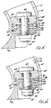
- Figure 5 is a view in isolation of an alternative embodiment of the piston head of the actuator and of an alternative embodiment of the manner in which the piston head is attached to the piston arm.
- Figure 6 is a view in isolation of an alternative embodiment of the piston head.
- The actuator of this invention has an
outer housing 10. In the preferred embodiment, thehousing 10 is of a circular configuration for greater compactness. Thehousing 10 is constructed from steel. The interior ofhousing 10 is a hollow cylinder containing afirst chamber 12 and asecond chamber 14. Thesecond chamber 14 is annular in configuration and in the preferred embodiment is in the shape of a toroid arc segment. To obtain greater precision, thereby reducing dimensional tolerances in thesecond chamber 14, the toroid segment is preferably cut, rather than cast. - The
housing 10 has a small opening at one end through which is inserted adrive shaft 16. The other end ofhousing 10 is open. Adiaphragm 18, having a central opening to fit over the end ofdrive shaft 16, fits into thehousing 10 to enclosechamber 12. - It will be appreciated that
housing 10 is generally a cylinder, closed at one end, and open at the other.Annular chamber 14 is formed at the bottom edge of the closed end of this cylinder. The remaining volume of the cylinder is open, defining a void space. This large void space becomesfirst chamber 12 afterdiaphragm 18 is inserted, but provides important advantages relating to the construction of the actuator. For example, it will be appreciated that this configuration allows apiston arm 40 and thedrive shaft 16 to be of unitized construction, rather than the splined attachment means typically utilized between the piston and drive shaft in other actuators. -
Thrust bearings drive shaft 16 and in the apertures in thehousing 10 anddiaphragm 18, respectively, to hold thedrive shaft 16 in place and to allow thedrive shaft 16 to rotate. Two sets of packing and retainer rings 24 and 26seal thrust bearing 20 againsthousing 10 and driveshaft 16 respectively; and two sets of packing and retainer rings 28 and 30 provide the same function between thrust bearing 22 anddiaphragm 18 and driveshaft 16. Another packing and retainer ring set 32 seals the exterior circumference of thediaphragm 18 againsthousing 10. Ametal split ring 34 is inserted into an appropriately sized aperture formed by corresponding grooves inhousing 10 anddiaphragm 18 to holddiaphragm 18 in place againsthousing 10. An access slot 36 (Figure 4) is provided in the exterior ofhousing 10 to allow thesplit ring 34 to be fed into position. A set screw 38 keeps thediaphragm 18 from turning in place relative to thehousing 10. - Looking at Figure 1, it will be seen that
piston arm 40 is formed integrally withdrive shaft 16 as they are of unitized construction. It will be understood that conventional attachment means could be used. It also will be appreciated that thefirst chamber 12 is of sufficient size to accommodate therein thepiston arm 40 and a portion of thedrive shaft 16. - On the heel of
piston arm 40 is attached a rubber stop 42. A shoulder 44 is formed on the interior ofhousing 10 against which rubber stop 42 abuts to stop movement of thepiston arm 40. -
Piston arm 40 is also formed as an arc segment of a toroid having an arc radius equal to that ofsecond chamber 14. The cross-sectional diameter ofpiston arm 40 is appreciably less than the interior cross-section diameter ofsecond chamber 14 so thatpiston arm 40 may move freely intosecond chamber 14. It will be appreciated that in order forpiston arm 40 to be able to move completely intosecond chamber 14, the center point for the arc radius ofpiston arm 40 must be the same as the center point for the arc radius forsecond chamber 14. It will further be appreciated that for improved compactness, whenpiston arm 40 is in the fully retracted position with rubber stop 42 against shoulder 44, thedistal end 46 ofpiston arm 40 is at or near the entrance tosecond chamber 14. -
Charging ports 48 and 50 provide the means whereby fluid under pressure can be introduced intofirst chamber 12 andsecond chamber 14, respectively. Threadedholes housing 10 for ease of attachment of the actuator to another surface. - A
piston head 58 is attached topiston arm 40 by means which allow thepiston head 58 to "float" in a lateral, or in the preferred embodiment, a radial manner relative topiston arm 40. These attachment means comprise acorner notch 60 formed inpiston arm 40 which presents ashoulder 62 which is parallel to the face 64 of thepiston arm 40. A hole is formed between the face 64 andshoulder 62. The hole is situated at the center point of face 64. Abolt 66 having anenlarged head 68 extends through that hole and is secured bynut 70 againstshoulder 62. The length ofbolt 66 is such that it extends an appreciable distance beyond the face 64 ofpiston arm 40. Theenlarged head 68 ofbolt 66 presents a shoulder 72 which is parallel to face 64. - The
piston head 58, which is preferably constructed of an aluminum-nickel-bronze alloy, is cup-shaped such that it has an interior cavity 74 of sufficient size to fit over theenlarged head 68 ofbolt 66. A portion of the interior surface of cavity 74 is threaded so as to receive a threaded insert 76 which retains thepiston head 58 uponenlarged head 68 ofbolt 66. It will be appreciated that the hole inpiston arm 40 betweenshoulder 62 and face 64 has an interior diameter equal to the exterior diameter ofbolt 66 such that there is no lateral or radial movement bybolt 66 in that hole. On the other hand, the interior diameter ofhole 78 in threaded insert 76 is appreciably larger than the exterior diameter ofbolt 66. Similarly, the interior diameter of cavity 74 is appreciably larger than the exterior diameter ofenlarged head 68. Accordingly,piston head 58 is capable of lateral or radial movement relative to bolt 66 and hence, relative topiston arm 40. It will further be appreciated that to provide for this lateral or radial movement, there must be some free space provided betweenpiston head 58 andpiston arm 40. This free space is obtained by making the interior cavity 74 andpiston head 58 appreciably deeper than thedistance bolt 66 extends away from face 64 ofpiston arm 40. Alock pin 65 is inserted into corresponding holes inpiston head 58 and insert 76 to prevent insert 76 from turning after it has been inserted. Wrenching hole 67 is added to insert 76 to aid in its insertion and removal. - Even though these provisions have been made to allow for radial or lateral movement of
piston head 58 relative topiston arm 40, it will be readily understood after having read the preceding material that ifsecond chamber 14 is subjected to high pressure, a tremendous force will be exerted againstpiston head 58 pushing it against the face 64 orpiston arm 40. The resultant friction betweenpiston head 58 and insert 76 against the face 64 ofpiston arm 40 will virtually preclude the free lateral movement ofpiston head 58. This completely vitiates the beneficial results expected by allowingpiston head 58 to float in the first instance. To counteract this phenomenon, a low friction thrust washer 82 is placed between face 64 ofpiston arm 40 and the threaded insert 76. Similarly, to prevent the resultant friction during engagement between the insert 76 ofpiston head 58 and the shoulder 72 of the enlarged head 68 (whencavity 12 is subjected to pressure) from interfering with free lateral movement, a lowfriction thrust washer 80 is placed between shoulder 72 and insert 76. Hence, it will be seen thatpiston head 58 is axially movable relative topiston arm 40 between a first position (see Figure 1), operable whenfirst chamber 12 is pressurised with fluid, in whichwasher 80 provides friction reduction for the lateral movement and a second position, operable whensecond chamber 14 is pressurised with fluid, in which washer 82 provided friction reduction for the lateral movement. Suitable thrust washers having a coating of a polytetrafluoroethylene-lead mixture which provides for exceptionally low friction. Therefore, even under substantial loads, thepiston head 58 will be able to float relative to thepiston arm 40. Therefore, during the travel of thepiston arm 40 through its arc insecond chamber 14, as thepiston arm 40 may flex during surges in pressure,orasthe piston head 58 encounters variances in the configurations of the walls ofsecond chamber 14, thepiston head 58 will more readily and with less friction float relative topiston arm 40 so that thepiston head 58 will adjust its position to seek the path of least resistance, thereby minimizing friction between it and the walls ofsecond chamber 14, producing maximized performance for the actuator. r. - In Figure 1, one of several embodiments for the configuration of the
piston head 58 is shown. Here it will be noted that the exterior configuration ofpiston head 58 is such that it contacts the walls ofsecond chamber 14 at one circumferential point only. Atthat point, a sealingring 84 is fitted into an appropriately sized groove formed inpiston head 58. The best performance is obtained by using asealing ring 84 which is resistant to extrusion under high pressure. - Another method of attachment of the
piston head 58 to thepiston arm 40 is shown in Figures 5 and 6. Here, thepiston head 58' and 58" does not have an interior cavity. Rather, the piston head has a centrally located aperture through whichbolt 66 is inserted. Another modification is made to face 64 ofpiston arm 40. The end ofpiston arm 40 is reduced in size to create ashoulder 100 and aneck portion 102. Thepiston head 58' and 58" has a small cavity which fits over theneck portion 102. To provide for movement of thepiston head 58' and 58" relative to the piston arm in this arrangement, the aperture 104 between face 64 andshoulder 62 is made appreciably larger than the size ofbolt 66. Aspacer 106 extends betweennut 70 and the underside of thepiston head 58' and 58" to allow for pretensioning of thebolt 66. This pretensioning of thebolt 66 increases its fatigue life, and also permits precise looseness between thepiston head 58' and 58" and thepiston arm 40. In this embodiment, thethrust washers 80 and 82 are placed between thepiston 58' and 58" head and face 64 and betweenshoulder 62 andnut 70. It will also be understood that because the aperture in the piston head is now exposed to fluid under pressure, packing andretainer ring 108 must be utilized. - Figures 5 and 6 also display alternative embodiments for the configuration of the piston head. Looking first to Figure 5, piston head 58' is in the shape of a toroid segment so that the sealing contact between the piston head 58' and the walls of
second chamber 14 is increased. This configuration finds its greatest utility in those applications where extremely high pressures are experienced. Although this configuration of piston head 58' presents a potential for greater friction between the piston head and the wall ofsecond chamber 14, the precision with which the toroidal bore ofsecond chamber 14 is machined, and the provision for low friction float of the piston head 58' during movement of thepiston arm 40, minimizes the increased frictional problems. - In Figure 6, another embodiment of
piston head 58" is shown. Here, the exterior piston surface is generated by a radius equal to that of theinterior surface 110 of the exterior wall portion ofsecond chamber 14.
Claims (11)
Priority Applications (3)
| Application Number | Priority Date | Filing Date | Title |
|---|---|---|---|
| EP84307815A EP0181971B1 (en) | 1984-11-12 | 1984-11-12 | Rotary actuator |
| AT84307815T ATE32369T1 (en) | 1984-11-12 | 1984-11-12 | ROTARY PISTON CYLINDER. |
| DE8484307815T DE3469206D1 (en) | 1984-11-12 | 1984-11-12 | Rotary actuator |
Applications Claiming Priority (1)
| Application Number | Priority Date | Filing Date | Title |
|---|---|---|---|
| EP84307815A EP0181971B1 (en) | 1984-11-12 | 1984-11-12 | Rotary actuator |
Publications (2)
| Publication Number | Publication Date |
|---|---|
| EP0181971A1 EP0181971A1 (en) | 1986-05-28 |
| EP0181971B1 true EP0181971B1 (en) | 1988-02-03 |
Family
ID=8192805
Family Applications (1)
| Application Number | Title | Priority Date | Filing Date |
|---|---|---|---|
| EP84307815A Expired EP0181971B1 (en) | 1984-11-12 | 1984-11-12 | Rotary actuator |
Country Status (3)
| Country | Link |
|---|---|
| EP (1) | EP0181971B1 (en) |
| AT (1) | ATE32369T1 (en) |
| DE (1) | DE3469206D1 (en) |
Cited By (3)
| Publication number | Priority date | Publication date | Assignee | Title |
|---|---|---|---|---|
| EP0493167A1 (en) * | 1990-12-28 | 1992-07-01 | Societe Europeenne De Propulsion | Rotary actuator with annular piston rod |
| WO1999046514A2 (en) | 1998-03-11 | 1999-09-16 | Eugen Rost | Drive arrangement actuated by a medium under pressure |
| WO2007003000A1 (en) * | 2005-06-30 | 2007-01-11 | James Antony Kells | Toroidal ram actuator |
Citations (4)
| Publication number | Priority date | Publication date | Assignee | Title |
|---|---|---|---|---|
| US163186A (en) * | 1875-05-11 | Improvement in oscillating engines | ||
| US2649077A (en) * | 1951-07-30 | 1953-08-18 | North American Aviation Inc | Piston assembly for oscillatory hydraulic actuators |
| US3444788A (en) * | 1965-12-13 | 1969-05-20 | Franz Sneen | Hydraulic annular piston motors |
| US3446120A (en) * | 1965-12-13 | 1969-05-27 | Franz Sneen | Oscillating fluid-driven actuator |
Family Cites Families (4)
| Publication number | Priority date | Publication date | Assignee | Title |
|---|---|---|---|---|
| FR522037A (en) * | 1920-05-20 | 1921-07-24 | Alphonse Haas | Piston |
| GB1140283A (en) * | 1966-01-17 | 1969-01-15 | Associated Cargo Gear Aktiebol | Improvements in or relating to pneumatic or hydraulic servo-motors |
| FR2076326A5 (en) * | 1970-01-09 | 1971-10-15 | Usinage Rationnel | |
| FR2253159A1 (en) * | 1974-11-07 | 1975-06-27 | Tenfjord Mek Verksted Johan | Hydraulic actuator for ship's rudder - ring shaped piston has spherical seating surfaces and houses locking rings |
-
1984
- 1984-11-12 EP EP84307815A patent/EP0181971B1/en not_active Expired
- 1984-11-12 DE DE8484307815T patent/DE3469206D1/en not_active Expired
- 1984-11-12 AT AT84307815T patent/ATE32369T1/en not_active IP Right Cessation
Patent Citations (4)
| Publication number | Priority date | Publication date | Assignee | Title |
|---|---|---|---|---|
| US163186A (en) * | 1875-05-11 | Improvement in oscillating engines | ||
| US2649077A (en) * | 1951-07-30 | 1953-08-18 | North American Aviation Inc | Piston assembly for oscillatory hydraulic actuators |
| US3444788A (en) * | 1965-12-13 | 1969-05-20 | Franz Sneen | Hydraulic annular piston motors |
| US3446120A (en) * | 1965-12-13 | 1969-05-27 | Franz Sneen | Oscillating fluid-driven actuator |
Cited By (6)
| Publication number | Priority date | Publication date | Assignee | Title |
|---|---|---|---|---|
| EP0493167A1 (en) * | 1990-12-28 | 1992-07-01 | Societe Europeenne De Propulsion | Rotary actuator with annular piston rod |
| FR2671145A1 (en) * | 1990-12-28 | 1992-07-03 | Europ Propulsion | ROTARY ACTUATION DEVICE WITH ANNULAR PISTON ROD. |
| US5235900A (en) * | 1990-12-28 | 1993-08-17 | Societe Europeenne De Propulsion | Rotary actuator device having an annular piston rod |
| WO1999046514A2 (en) | 1998-03-11 | 1999-09-16 | Eugen Rost | Drive arrangement actuated by a medium under pressure |
| WO2007003000A1 (en) * | 2005-06-30 | 2007-01-11 | James Antony Kells | Toroidal ram actuator |
| US7895935B2 (en) | 2005-06-30 | 2011-03-01 | James Antony Kells | Toroidal ram actuator |
Also Published As
| Publication number | Publication date |
|---|---|
| DE3469206D1 (en) | 1988-03-10 |
| ATE32369T1 (en) | 1988-02-15 |
| EP0181971A1 (en) | 1986-05-28 |
Similar Documents
| Publication | Publication Date | Title |
|---|---|---|
| US4628797A (en) | Rotary actuator | |
| EP0013266B1 (en) | Hydraulic actuator for a subsea gate valve having a manual override | |
| US4445424A (en) | Actuator having Belleville washer configuration operating in concert with a piston cylinder member | |
| US4523516A (en) | Actuator having Belleville washer configuration operating in concert with a piston cylinder member | |
| EP1896730B1 (en) | Toroidal ram actuator | |
| EP0050466A1 (en) | Rotary valve actuator | |
| KR890001394B1 (en) | Hydraulic actuator | |
| US4564169A (en) | Fluid actuator for stepwise regulation of valves | |
| US3063423A (en) | Seal means for hydraulic actuator | |
| JPH01312207A (en) | Spring return cylinder actuator | |
| EP0181971B1 (en) | Rotary actuator | |
| US4545289A (en) | Adjustable rotary actuator | |
| US5165322A (en) | Three position power cylinder | |
| US2708879A (en) | Power transmission | |
| US5488896A (en) | Self aligning piston rod | |
| US4922805A (en) | Fluid actuated cylinder | |
| CA1226787A (en) | Rotary actuator | |
| US4258902A (en) | Steering valve with annular sealing element for radial annular gap | |
| US7185852B2 (en) | Actuator with helical cam guides | |
| CN113819108B (en) | Digital spiral swing fluid cylinder | |
| US4665764A (en) | Rotary actuator | |
| US4394787A (en) | Hydraulic door closer construction | |
| US3964371A (en) | Power boost steering mechanism | |
| US4706513A (en) | Rack and pinion power steering apparatus | |
| JPH0369003B2 (en) |
Legal Events
| Date | Code | Title | Description |
|---|---|---|---|
| PUAI | Public reference made under article 153(3) epc to a published international application that has entered the european phase |
Free format text: ORIGINAL CODE: 0009012 |
|
| AK | Designated contracting states |
Kind code of ref document: A1 Designated state(s): AT BE CH DE FR GB IT LI LU NL SE |
|
| 17P | Request for examination filed |
Effective date: 19860820 |
|
| 17Q | First examination report despatched |
Effective date: 19861103 |
|
| GRAA | (expected) grant |
Free format text: ORIGINAL CODE: 0009210 |
|
| ITF | It: translation for a ep patent filed |
Owner name: NOTARBARTOLO & GERVASI S.R.L. |
|
| AK | Designated contracting states |
Kind code of ref document: B1 Designated state(s): AT BE CH DE FR GB IT LI LU NL SE |
|
| REF | Corresponds to: |
Ref document number: 32369 Country of ref document: AT Date of ref document: 19880215 Kind code of ref document: T |
|
| REF | Corresponds to: |
Ref document number: 3469206 Country of ref document: DE Date of ref document: 19880310 |
|
| ET | Fr: translation filed | ||
| PLBE | No opposition filed within time limit |
Free format text: ORIGINAL CODE: 0009261 |
|
| STAA | Information on the status of an ep patent application or granted ep patent |
Free format text: STATUS: NO OPPOSITION FILED WITHIN TIME LIMIT |
|
| 26N | No opposition filed | ||
| PGFP | Annual fee paid to national office [announced via postgrant information from national office to epo] |
Ref country code: GB Payment date: 19911017 Year of fee payment: 8 |
|
| PGFP | Annual fee paid to national office [announced via postgrant information from national office to epo] |
Ref country code: SE Payment date: 19911022 Year of fee payment: 8 |
|
| PGFP | Annual fee paid to national office [announced via postgrant information from national office to epo] |
Ref country code: AT Payment date: 19911029 Year of fee payment: 8 |
|
| PGFP | Annual fee paid to national office [announced via postgrant information from national office to epo] |
Ref country code: FR Payment date: 19911120 Year of fee payment: 8 |
|
| PGFP | Annual fee paid to national office [announced via postgrant information from national office to epo] |
Ref country code: DE Payment date: 19911128 Year of fee payment: 8 |
|
| ITTA | It: last paid annual fee | ||
| PGFP | Annual fee paid to national office [announced via postgrant information from national office to epo] |
Ref country code: NL Payment date: 19911130 Year of fee payment: 8 |
|
| PGFP | Annual fee paid to national office [announced via postgrant information from national office to epo] |
Ref country code: BE Payment date: 19911217 Year of fee payment: 8 |
|
| PGFP | Annual fee paid to national office [announced via postgrant information from national office to epo] |
Ref country code: CH Payment date: 19920113 Year of fee payment: 8 |
|
| PGFP | Annual fee paid to national office [announced via postgrant information from national office to epo] |
Ref country code: LU Payment date: 19920325 Year of fee payment: 8 |
|
| EPTA | Lu: last paid annual fee | ||
| PG25 | Lapsed in a contracting state [announced via postgrant information from national office to epo] |
Ref country code: LU Free format text: LAPSE BECAUSE OF NON-PAYMENT OF DUE FEES Effective date: 19921112 Ref country code: GB Effective date: 19921112 Ref country code: AT Effective date: 19921112 |
|
| PG25 | Lapsed in a contracting state [announced via postgrant information from national office to epo] |
Ref country code: SE Effective date: 19921113 |
|
| PG25 | Lapsed in a contracting state [announced via postgrant information from national office to epo] |
Ref country code: LI Effective date: 19921130 Ref country code: CH Effective date: 19921130 Ref country code: BE Effective date: 19921130 |
|
| BERE | Be: lapsed |
Owner name: MENASCO INC. Effective date: 19921130 |
|
| PG25 | Lapsed in a contracting state [announced via postgrant information from national office to epo] |
Ref country code: NL Effective date: 19930601 |
|
| GBPC | Gb: european patent ceased through non-payment of renewal fee |
Effective date: 19921112 |
|
| NLV4 | Nl: lapsed or anulled due to non-payment of the annual fee | ||
| PG25 | Lapsed in a contracting state [announced via postgrant information from national office to epo] |
Ref country code: FR Effective date: 19930730 |
|
| REG | Reference to a national code |
Ref country code: CH Ref legal event code: PL |
|
| PG25 | Lapsed in a contracting state [announced via postgrant information from national office to epo] |
Ref country code: DE Effective date: 19930803 |
|
| REG | Reference to a national code |
Ref country code: FR Ref legal event code: ST |
|
| EUG | Se: european patent has lapsed |
Ref document number: 84307815.5 Effective date: 19930610 |