EP0181402B1 - Fuel injection pump - Google Patents
Fuel injection pump Download PDFInfo
- Publication number
- EP0181402B1 EP0181402B1 EP85901582A EP85901582A EP0181402B1 EP 0181402 B1 EP0181402 B1 EP 0181402B1 EP 85901582 A EP85901582 A EP 85901582A EP 85901582 A EP85901582 A EP 85901582A EP 0181402 B1 EP0181402 B1 EP 0181402B1
- Authority
- EP
- European Patent Office
- Prior art keywords
- plunger
- fuel
- control
- fuel injection
- injection
- Prior art date
- Legal status (The legal status is an assumption and is not a legal conclusion. Google has not performed a legal analysis and makes no representation as to the accuracy of the status listed.)
- Expired
Links
Images








Classifications
-
- F—MECHANICAL ENGINEERING; LIGHTING; HEATING; WEAPONS; BLASTING
- F02—COMBUSTION ENGINES; HOT-GAS OR COMBUSTION-PRODUCT ENGINE PLANTS
- F02M—SUPPLYING COMBUSTION ENGINES IN GENERAL WITH COMBUSTIBLE MIXTURES OR CONSTITUENTS THEREOF
- F02M59/00—Pumps specially adapted for fuel-injection and not provided for in groups F02M39/00 -F02M57/00, e.g. rotary cylinder-block type of pumps
- F02M59/20—Varying fuel delivery in quantity or timing
- F02M59/24—Varying fuel delivery in quantity or timing with constant-length-stroke pistons having variable effective portion of stroke
- F02M59/243—Varying fuel delivery in quantity or timing with constant-length-stroke pistons having variable effective portion of stroke caused by movement of cylinders relative to their pistons
-
- F—MECHANICAL ENGINEERING; LIGHTING; HEATING; WEAPONS; BLASTING
- F02—COMBUSTION ENGINES; HOT-GAS OR COMBUSTION-PRODUCT ENGINE PLANTS
- F02D—CONTROLLING COMBUSTION ENGINES
- F02D1/00—Controlling fuel-injection pumps, e.g. of high pressure injection type
- F02D1/02—Controlling fuel-injection pumps, e.g. of high pressure injection type not restricted to adjustment of injection timing, e.g. varying amount of fuel delivered
- F02D1/08—Transmission of control impulse to pump control, e.g. with power drive or power assistance
- F02D1/12—Transmission of control impulse to pump control, e.g. with power drive or power assistance non-mechanical, e.g. hydraulic
-
- F—MECHANICAL ENGINEERING; LIGHTING; HEATING; WEAPONS; BLASTING
- F02—COMBUSTION ENGINES; HOT-GAS OR COMBUSTION-PRODUCT ENGINE PLANTS
- F02M—SUPPLYING COMBUSTION ENGINES IN GENERAL WITH COMBUSTIBLE MIXTURES OR CONSTITUENTS THEREOF
- F02M41/00—Fuel-injection apparatus with two or more injectors fed from a common pressure-source sequentially by means of a distributor
- F02M41/02—Fuel-injection apparatus with two or more injectors fed from a common pressure-source sequentially by means of a distributor the distributor being spaced from pumping elements
- F02M41/06—Fuel-injection apparatus with two or more injectors fed from a common pressure-source sequentially by means of a distributor the distributor being spaced from pumping elements the distributor rotating
-
- F—MECHANICAL ENGINEERING; LIGHTING; HEATING; WEAPONS; BLASTING
- F02—COMBUSTION ENGINES; HOT-GAS OR COMBUSTION-PRODUCT ENGINE PLANTS
- F02M—SUPPLYING COMBUSTION ENGINES IN GENERAL WITH COMBUSTIBLE MIXTURES OR CONSTITUENTS THEREOF
- F02M59/00—Pumps specially adapted for fuel-injection and not provided for in groups F02M39/00 -F02M57/00, e.g. rotary cylinder-block type of pumps
- F02M59/02—Pumps specially adapted for fuel-injection and not provided for in groups F02M39/00 -F02M57/00, e.g. rotary cylinder-block type of pumps of reciprocating-piston or reciprocating-cylinder type
- F02M59/10—Pumps specially adapted for fuel-injection and not provided for in groups F02M39/00 -F02M57/00, e.g. rotary cylinder-block type of pumps of reciprocating-piston or reciprocating-cylinder type characterised by the piston-drive
- F02M59/102—Mechanical drive, e.g. tappets or cams
-
- F—MECHANICAL ENGINEERING; LIGHTING; HEATING; WEAPONS; BLASTING
- F02—COMBUSTION ENGINES; HOT-GAS OR COMBUSTION-PRODUCT ENGINE PLANTS
- F02M—SUPPLYING COMBUSTION ENGINES IN GENERAL WITH COMBUSTIBLE MIXTURES OR CONSTITUENTS THEREOF
- F02M59/00—Pumps specially adapted for fuel-injection and not provided for in groups F02M39/00 -F02M57/00, e.g. rotary cylinder-block type of pumps
- F02M59/20—Varying fuel delivery in quantity or timing
- F02M59/24—Varying fuel delivery in quantity or timing with constant-length-stroke pistons having variable effective portion of stroke
- F02M59/243—Varying fuel delivery in quantity or timing with constant-length-stroke pistons having variable effective portion of stroke caused by movement of cylinders relative to their pistons
- F02M59/246—Mechanisms therefor
-
- F—MECHANICAL ENGINEERING; LIGHTING; HEATING; WEAPONS; BLASTING
- F02—COMBUSTION ENGINES; HOT-GAS OR COMBUSTION-PRODUCT ENGINE PLANTS
- F02M—SUPPLYING COMBUSTION ENGINES IN GENERAL WITH COMBUSTIBLE MIXTURES OR CONSTITUENTS THEREOF
- F02M59/00—Pumps specially adapted for fuel-injection and not provided for in groups F02M39/00 -F02M57/00, e.g. rotary cylinder-block type of pumps
- F02M59/20—Varying fuel delivery in quantity or timing
- F02M59/24—Varying fuel delivery in quantity or timing with constant-length-stroke pistons having variable effective portion of stroke
- F02M59/26—Varying fuel delivery in quantity or timing with constant-length-stroke pistons having variable effective portion of stroke caused by movements of pistons relative to their cylinders
-
- F—MECHANICAL ENGINEERING; LIGHTING; HEATING; WEAPONS; BLASTING
- F02—COMBUSTION ENGINES; HOT-GAS OR COMBUSTION-PRODUCT ENGINE PLANTS
- F02M—SUPPLYING COMBUSTION ENGINES IN GENERAL WITH COMBUSTIBLE MIXTURES OR CONSTITUENTS THEREOF
- F02M59/00—Pumps specially adapted for fuel-injection and not provided for in groups F02M39/00 -F02M57/00, e.g. rotary cylinder-block type of pumps
- F02M59/20—Varying fuel delivery in quantity or timing
- F02M59/24—Varying fuel delivery in quantity or timing with constant-length-stroke pistons having variable effective portion of stroke
- F02M59/26—Varying fuel delivery in quantity or timing with constant-length-stroke pistons having variable effective portion of stroke caused by movements of pistons relative to their cylinders
- F02M59/28—Mechanisms therefor
-
- F—MECHANICAL ENGINEERING; LIGHTING; HEATING; WEAPONS; BLASTING
- F02—COMBUSTION ENGINES; HOT-GAS OR COMBUSTION-PRODUCT ENGINE PLANTS
- F02M—SUPPLYING COMBUSTION ENGINES IN GENERAL WITH COMBUSTIBLE MIXTURES OR CONSTITUENTS THEREOF
- F02M59/00—Pumps specially adapted for fuel-injection and not provided for in groups F02M39/00 -F02M57/00, e.g. rotary cylinder-block type of pumps
- F02M59/20—Varying fuel delivery in quantity or timing
- F02M59/36—Varying fuel delivery in quantity or timing by variably-timed valves controlling fuel passages to pumping elements or overflow passages
-
- F—MECHANICAL ENGINEERING; LIGHTING; HEATING; WEAPONS; BLASTING
- F02—COMBUSTION ENGINES; HOT-GAS OR COMBUSTION-PRODUCT ENGINE PLANTS
- F02M—SUPPLYING COMBUSTION ENGINES IN GENERAL WITH COMBUSTIBLE MIXTURES OR CONSTITUENTS THEREOF
- F02M59/00—Pumps specially adapted for fuel-injection and not provided for in groups F02M39/00 -F02M57/00, e.g. rotary cylinder-block type of pumps
- F02M59/44—Details, components parts, or accessories not provided for in, or of interest apart from, the apparatus of groups F02M59/02 - F02M59/42; Pumps having transducers, e.g. to measure displacement of pump rack or piston
- F02M59/46—Valves
- F02M59/462—Delivery valves
-
- F—MECHANICAL ENGINEERING; LIGHTING; HEATING; WEAPONS; BLASTING
- F02—COMBUSTION ENGINES; HOT-GAS OR COMBUSTION-PRODUCT ENGINE PLANTS
- F02M—SUPPLYING COMBUSTION ENGINES IN GENERAL WITH COMBUSTIBLE MIXTURES OR CONSTITUENTS THEREOF
- F02M59/00—Pumps specially adapted for fuel-injection and not provided for in groups F02M39/00 -F02M57/00, e.g. rotary cylinder-block type of pumps
- F02M59/44—Details, components parts, or accessories not provided for in, or of interest apart from, the apparatus of groups F02M59/02 - F02M59/42; Pumps having transducers, e.g. to measure displacement of pump rack or piston
- F02M59/48—Assembling; Disassembling; Replacing
-
- F—MECHANICAL ENGINEERING; LIGHTING; HEATING; WEAPONS; BLASTING
- F02—COMBUSTION ENGINES; HOT-GAS OR COMBUSTION-PRODUCT ENGINE PLANTS
- F02M—SUPPLYING COMBUSTION ENGINES IN GENERAL WITH COMBUSTIBLE MIXTURES OR CONSTITUENTS THEREOF
- F02M2200/00—Details of fuel-injection apparatus, not otherwise provided for
- F02M2200/24—Fuel-injection apparatus with sensors
Definitions
- the present invention relates to a fuel injection pump device for injecting fuel into the combustion chamber of an internal combustion engine.
- a fuel injection pump device for pumping fuel into the fuel injection nozzle of a Diesel engine has been hitherto composed so that the control of a fuel injection quantity is carried out by turning a plunger for pressurizing the fuel in the pump, and composed so that the control of a fuel injection beginning time is carried out by changing the rotating phase of a cam shaft for driving said plunger, which is driven by the engine, with respect to the crank angular phase of the engine by use of a centrifugal auto-timer provided on the cam shaft.
- the prior art presents various pump devices for injecting fuel into a combustion chamber.
- US-A-3 847 126 discloses a fuel injection control linkage for timing and metering fuel injection on a multiple plunger fuel injection pump with modulation responsive to engine parameters such as engine speed and load.
- EP-A-0 075 802 describes a pump similar to this last.
- the present invention proposes a fuel injection pump device which comprises a delivery valve communicated with a pressurizing chamber formed in a housing loaded by a spring and communicated with a fuel injection nozzle, a plunger with its one end facing the pressurizing chamber and the other end operatively connected with a cam which is driven by an engine, a fuel chamber provided so as to surround the plunger in the housing; a fuel passage formed inside of the plunger so that its one end communicates to the pressurizing chamber and the other end communicates to the fuel chamber; a control sleeve slidably mounted on the outer periphery of the plunger in the fuel chamber; a control groove arrangement provided on the outer peripheral surface of the plunger and connected with the fuel passage for communicating the pressurizing chamber and fuel chamber to each other or interrupting both of them, said control groove arrangement having an inclined groove portion provided slantedly with respect to the axis of the plunger and a longitudinal groove portion provided parallel to the plunger axis; a control port provided in
- the fuel injection pump device Since the delivery pressure from the fuel injection pump device is furthermore prevented from rising more by moving the control sleeve to advance the injection timing when the engine is in a high speed region, the fuel injection pump is not damaged. In addition, since the fuel injection pump is not damaged even when the engine is in the high speed region, its delivery pressure in the medium and low speed regions of the engine can be increased, the fuel consumption can be lowered and the black smoke in the exhaust gas can be reduced in quantity.
- the reference numeral 2 represents a housing of an in-line fuel injection pump for a Diesel engine
- 4 represents one of a plurality of barrels in the housing, which barrels 4 are positioned so that their axes stand in rows on one plane in the housing 2.
- This barrel 4 is composed of a first barrel part 4a and a second barrel part 4b press-fitted thereon.
- the reference numeral 6 represents a delivery valve holder fixed on the top of each barrel 4, which holder is to be connected to the respective cylinders of an engine; 7a is a delivery valve; 8 is a plunger slidably mounted in each barrel 4; 10 is a spring for biasing the plunger downwards; 12 is a cam interlocked with a driving shaft (not shown) of an engine to push up the plunger 8; 14 is a control sleeve slidably mounted on the outer periphery of the plunger 8; 16 is a guide pin fixed on each barrel 4 and engaged in a guide groove 17 of the control sleeve 14 to restrain its turn; and 18 is a sleeve turnably supported on the barrel 4 but non-turnably engaged with the plunger 8.
- the plunger 8 has an oil passage 8a which communicates its upper end face and its peripheral side to each other, peripheral side openings 8b formed on the peripheral side in communication with the oil passage 8a, a longitudinal groove 8c cut on the peripheral side so as to continue to the opening 8b and to run along the axis of the plunger 8, and an inclined groove 8d intersecting this longitudinal groove 8c and slanting to the plunger axis, wherein a control groove is formed by both these grooves 8c and 8d and the oil feed ports 8b (which will be hereinafter called “the openings").
- control ports 14a are perforated to define a fuel injection end.
- the reference numeral 15 represents a fuel chamber for storing fuel fed from a feed pump (not shown), wherein the fuel is not leaked into a cam shaft case 13, because the plunger 8 is inserted in the cylindrical second barrel part 4b, with an oil-tight state held between them.
- the reference numeral 21 represents an oil feed opening through which lubricating oil is fed to the cam shaft case 13, and 23 represents a guide pin protruded on a tappet 25 and slidably engaged in a guide groove 27 cut in the housing 2.
- the reference numeral 29 shown in Fig. 3 represents an adjustment screw (not shown in Fig. 4 and Fig. 11) screwed in a screw hole of an operation shaft 26 mentioned below, wherein the fuel injection timing can be finely adjusted by relaxing the screw 29 to rotate a lever 28 properly.
- the plunger 8 When the cam 12 is rotated one time by a cam shaft 12a driven by the rotating force received from the driving shaft of the engine and the roller 25a of the tappet 25 is pressed by the cam 12, according to the abovementioned composition, the plunger 8 will be reciprocated upwards by a given lift or vertically at one stroke.
- the pressurizing chamber 20 is interrupted from the fuel chamber 15 and pressurized by the plunger 8.
- This stroke of the plunger 8 which moves between the states (a) and (c) is called a prestroke.
- the delivery pressure in the pressurizing chamber 20 overcomes the spring force of a spring 7b in the delivery valve holder 6 and the delivery valve 7a is opened so that high-pressure fuel is fed to an injection nozzle V through an injection tube 6a.
- the fuel is being pumped out until the inclined groove 8d of the plunger 8 communicates with the control port 14a as shown in Fig. 10(e).
- the pressurizing chamber 20 begins to communicates with the fuel chamber 15 by way of the oil passage 8a, opening 8b and longitudinal groove 8c, and as a result, the pumping of fuel comes to an end. Since the inclined groove 8d extends on the outer periphery of the plunger 8 so as to slant with respect to its axis, as can be seen from Fig. 5, the confrontation time of the inclined groove 8d with the control ports 14a of the control sleeve 14 in the stroke of the plunger 8 can be changed by the turning displacement of the plunger 8 caused by the sleeve 18, whereby the fuel injection quantity in one stroke of the plunger 8 can be regulated. In addition, the displacement of the sleeve 18 in its turning direction is carried out by displacing a rack 24 which engages with a ball 22 secured on the sleeve 18 in its longitudinal direction.
- the present invention is arranged such that the length 1 4 between the control sleeve 14 and the control port 14a is set to be shorter than the length 1 3 between the upper end of the longitudinal groove 8c and the control port 14a when the plunger 8 is in its upmost stroked position, as shown in Fig. 7.
- the two-stage blasting of fuel can be prevented.
- this invention is arranged such that the length 1 1 of the longitudinal groove 8c in the direction of the plunger axis is set to be larger than the length 1 2 between the lower end of the control sleeve 14 and the control port 14a, as shown in Fig. 8. By this arrangement, no injection of fuel can be achieved.
- JP-U-59 52175 is somewhat similar in its construction to this invention, it does not disclose nor suggest the above arrangement for preventing two-stage blasting of fuel.
- US ⁇ A ⁇ 2 813 523 relates to the distributor type fuel injection pump in which the plunger is slided in the axial direction simultaneously with its rotation and which is of a type different from this invention.
- the slots merely act to define the beginning and ending of injection.
- the fuel injection timing control mechanism will be described here.
- the control of the fuel injection timing is conducted by the sliding displacement of the control sleeve 14 along the plunger 8, and this sliding displacment is carried out by means of an operation shaft 26 supported in the housing 2 so as to lie by the side of the control sleeve 14 and having its axis on one straight line parallel to a plane on which the aforementioned barrels 4 stand in rows and perpendicular to the axis of the plunger 8, the lever 28 fixed on the operation shaft 26 and extended from the operation sahft toward the plunger 8, and a notched groove 14b formed on the outer peripheral surface of the control sleeve 14, which is engaged with the fore end of the lever 28 to interlock the turning displacement of the lever 28 around the operation shaft 26 and the sliding displacement of the control sleeve 14.
- the outer peripheral surface of the lever 28 at its end has such a curvature that it is always in contact with the inner peripheral surface of the notched groove 14b, without giving any play between them.
- the support part 26a of the operation shaft 26 at each end is supported on the housing 2 by way of a bearing 30 having an outer diameter which is larger than an external dimension including the operation shaft 26 and lever 28 in the direction of the diameter of the operation shaft 26, with a plate 32 disposed between one end of the bearing 30 and the housing 2.
- the reference numeral 34 represents a snap ring which serves to prevent the bearing 30 secured in the housing 2 from slipping out of the housing
- 36 represents a positioning pin embedded in the bearing 30 and running through the plate 32 to engage with the housing 2.
- the turning displacement of the operation shaft 26 is conducted by means of an operation lever 40 fixed on one end of the operation shaft 26 and an electromagnetic solenoid 44 supported on the housing 2 by a bracket 41, which turns the operation lever 40 by way of a slider 42, as shown in Figs. 1, 2 and 4.
- a potentiometer 46 for measuring the turning displacement of the operation lever 40 is further supported on the bracket 41. As shown in Fig.
- a control unit 52 is composed so that various informations on the operating state of the engine from operating state information sources 50, for example an engine speed, degree of an accelerator pedal depression, temperature of cooling water, temperature of intake air, boost pressure of an air intake system and temperature of exhaust gas, and the information on the turning displacement of the operation shaft 26 from the potentiometer 46 are sent to the control unit and these informations are calculated synthetically, thereby to obtain a control of accurate injection timing. It is possible to adopt a differential transformer type sensor in place of this potentiometer 26. In the aforementioned embodiment, it is also possible to turn the operation lever 40 by a hydraulic cylinder in place of the electromagnetic solenoid 44.
- the rack 24 constitutes a fuel injection quantity control member
- the operation shaft 26, operation lever 40 and slider 42 constitute a fuel injection timing control member.
- a fuel injection control means is made up of a governor (the minimum-maximum type or the all-speed type) (not shown) for driving the rack 24, the control unit 52 and the electromagnetic solenoid 44.
- the pump Since the pump has the aforementioned composition, it has such operational effects as mentioned below.
- the plunger 8 By turning the plunger 8 around its axis to change the relatively related position of the control port 14a to the inclined groove 8d forming a part of the control groove, namely, the effective stroke of the plunger is changed whereby the fuel injection quantity can be regulated.
- the longitudinal groove 8c By causing the longitudinal groove 8c to accord with the control port 14a, the state of no fuel injection can be achieved as shown in Fig. 8.
- the turning displacement of the operation shaft 26 having the lever 28 causes the control sleeve 14 to displace in the direction of the plunger axis.
- the prestroke of the plunger is changed, whereby the injection timing can be adjusted.
- a modification of the control groove in the aforementioned embodiment may be a control groove comprising openings 8b communicating with a longitudinal groove 8c, an inclined groove 8d and the oil passage 8a in the plunger.
- the inner diameter d 1 of the control port is set to be larger than the distance do between both the grooves 8c and 8d, in order to ensure a state of no fuel injection.
- the relation between the revolution number of the cam shaft and the delivery pressure of the pump is represented by the graph M.
- the limit of the withstanding pressure in use of the pump is 800 kg/cm 2 at that time
- the delivery pressure for fuel is increased by the plunger 8 with the increase in the engine speed, when the cam angle shown in the cam diagram of Fig. 20 falls within the range 8 1 in the so-called medium and low engine speed regions wherein the revolution number of the cam shaft varies from 500 to about 900 r.p.m.
- the revolution number of the cam shaft becomes about 900 r.p.m.
- the delivery pressure reaches the withstanding pressure in use of the pump.
- the control sleeve 14 is moved downward by a given distance along the plunger 8.
- the prestroke of the plunger 8 becomes short and as a result, fuel is injected with the speed constant directed in the direction of the arrow, or the cam angle falling within the range 6 2 , as shown in Fig. 20.
- fuel is supplied from the fuel injection pump to the engine at the constant and maximum delivery pressure M" regardless of the engine speed, as shown in Fig. 18.
- the injection timing is controlled so as to be advanced, whereby the fuel is injected into a combustion chamber at a proper time and mixed with air in said chamber for combustion.
- each injection pump of the types A to J is set, as shown by the single-dotted chain line in the graph of Fig. 18, so that the delivery pressure of the pump reaches a state almost near to the limit of the withstanding pressure of the .pump itself, when an engine is being operated in the maximum speed region, and the injection timing control is conducted by changing the rotating phase of the cam shaft with respect to the crank angular phase of the engine gradually, when the engine is in the medium speed region.
- FIG. 20 A cam diagram which will be obtained by shaping the profile of the cam 12 in a cam contour having the dimension shown in Fig. 19 and determining the lift thereof at 14 mm, is shown in Fig. 20.
- the geometrical average oil feed ratio Vp obtained in this connection is sought as follows: and this is described as the point P in the graph of Fig. 17.
- the average oil feed ratios Vp must fall within such a range (this is the obliquely lined portion in Fig. 17) that the related expression is satisfied between both the relations of the straight line which connects the point Q and point S and the straight line on the basis of Vp existing in that range.
- the sign V s used here expresses a piston displacement (1) per a single cylinder of the engine.
- the engine output can be increased because it acts as a fuel injection pump whose delivery pressure is high when the engine is in medium and low speed regions, and the engine can be operated under the optimum control because it is kept at the state of the maximum delivery pressure and its injection timing is advanced when the engine is in a high speed region.
- the fuel injection pump of this invention (by the solid line) is composed so that the injection time becomes shorter throughout the whole of the engine speed regions, as compared with the aforementioned conventional injection pumps (by the single-dotted chain line), and it has various operational effects such as an improvement in the rate of fuel consumption proportional to the injection time shortened and an improvement in the exhaust gas performance of the engine.
- the pump withstanding pressure 800 kg/cm 2
- the pump withstanding pressure is not limited to the value.
- the delivery pressure has been made to accord almost with the pump withstanding pressure between the points M'" and M", but the prestroke of the pump may be controlled as a matter of course so that the delivery pressure is below its withstanding pressure.
- the cam has been used having the profile shown in Fig. 19. If the radius of the cam profile at the point R, is made large, there will be obtained a speed constant diagram in the form of such a trapezoid as shown by the double dotted chain line a-b-c-d in Fig. 20. In the case of this profile, the speed constant between the points b-c becomes almost constant (although not shown, the lift curve of this cam must be also changed). If an injection of fuel is carried out in the range of this cam angle, which connects the point R and point U, as shown in Fig.
- the plunger diameter D and cam lift h can be selected for adaptation so as to satisfy the related expression fuel particles injected into the combustion chamber will become small and they will be dispersed satisfactorily in the combustion chamber and burnt effectively here, because the average pressure of this injection is larger. And besides, the selection range for the injection timing (in particular the advance timing) will be widened, because the average injection pressure is large.
Landscapes
- Engineering & Computer Science (AREA)
- Chemical & Material Sciences (AREA)
- Combustion & Propulsion (AREA)
- Mechanical Engineering (AREA)
- General Engineering & Computer Science (AREA)
- Fuel-Injection Apparatus (AREA)
Abstract
Description
- The present invention relates to a fuel injection pump device for injecting fuel into the combustion chamber of an internal combustion engine.
- A fuel injection pump device for pumping fuel into the fuel injection nozzle of a Diesel engine has been hitherto composed so that the control of a fuel injection quantity is carried out by turning a plunger for pressurizing the fuel in the pump, and composed so that the control of a fuel injection beginning time is carried out by changing the rotating phase of a cam shaft for driving said plunger, which is driven by the engine, with respect to the crank angular phase of the engine by use of a centrifugal auto-timer provided on the cam shaft. In the case where the injection timing is controlled, however, the inertia mass of the cam shaft is relatively larger and the pump driving torque transmitted from the cam shaft to the plunger is large, and such a conventional fuel injection pump device is therefore disadvantageous: a large-sized timer must be used as an inevitable consequence, the cost is accordingly increased and the whole of the pump is made large-scaled.
- The prior art presents various pump devices for injecting fuel into a combustion chamber.
- US-A-3 847 126 discloses a fuel injection control linkage for timing and metering fuel injection on a multiple plunger fuel injection pump with modulation responsive to engine parameters such as engine speed and load.
- EP-A-0 075 802 describes a pump similar to this last.
- Other pumps of the type above quoted are described in DE-A-3 017 730, GB-A-2 109 059, US―A―3 815 564, US-A-2 147 390, FR-A-833 992 and GB-A-679 006, the most relevant of which are discussed later.
- It is the main object of the invention to obtain an injection pump having a simple structure with an auto-timer omitted, in which the control of a fuel injection timing can be realized by a small operating force.
- In order to achieve this object, the present invention proposes a fuel injection pump device which comprises a delivery valve communicated with a pressurizing chamber formed in a housing loaded by a spring and communicated with a fuel injection nozzle, a plunger with its one end facing the pressurizing chamber and the other end operatively connected with a cam which is driven by an engine, a fuel chamber provided so as to surround the plunger in the housing; a fuel passage formed inside of the plunger so that its one end communicates to the pressurizing chamber and the other end communicates to the fuel chamber; a control sleeve slidably mounted on the outer periphery of the plunger in the fuel chamber; a control groove arrangement provided on the outer peripheral surface of the plunger and connected with the fuel passage for communicating the pressurizing chamber and fuel chamber to each other or interrupting both of them, said control groove arrangement having an inclined groove portion provided slantedly with respect to the axis of the plunger and a longitudinal groove portion provided parallel to the plunger axis; a control port provided in the control sleeve collaborating with the inclined and longitudinal groove portions, and communicating the control groove arrangement to the fuel chamber when a fuel injection is completed; an injection quantity control member supported on the housing and turning the plunger for controlling a fuel injection quantity; an injection timing control member moving the control sleeve in the axial direction of the plunger; and fuel injection control means controlling the injection quantity control member and the injection timing control member in accordance with signals from operating state information sources, characterized in that the fuel injection control means is arranged to actuate the injection timing control member for advancing injection timing on the basis of the information of the engine in a high speed region from the operating state information sources, and that the inclined groove portion is formed so as to intersect the portion of the longitudinal groove portion other than both its ends, or is formed so as to separate from the longitudinal groove portion whereby the minimum space between the inclined groove portion and longitudinal groove portion in the direction perpendicular to the plunger axis is made shorter than the diameter of the corresponding control port and that the length of the longitudinal groove portion in the direction of the plunger axis is set to be shorter than the length of the control sleeve in its sliding direction and to be larger than the length between the end of the control sleeve in direction opposite to the pressurizing chamber and the control port, the length between the end of the control sleeve in direction to the pressurizing chamber and the control port is set to be shorter than the length between the end of the longitudinal groove portion in direction to the pressurizing chamber and the control port when the plunger is under the control for minimum effective stroke according to the minimum fuel injection quantity by virtue of the operation of the injection quantity control member and the plunger is at an advanced position, following a fuel injection on that stroke, where the control groove arrangement no longer communicates with the control port, whereby two-stage blasting of fuel is prevented, and the length between the end of the control sleeve in direction to the pressurizing chamber and the control port is set to be shorter than the length of the longitudinal groove portion, whereby no injection of fuel is obtained during a plunger stroke when the plunger and control sleeve are controlled, by operation of the injection quantity control member, such that the longitudinal groove portion and the control port are substantially axially aligned with each other.
- According to this composition, it is sufficient only to move the control sleeve in said axial direction, with a small force required for this operation, and it is possible to make up the structure of an injection timing control member for actuating the control sleeve simply.
- Since the delivery pressure from the fuel injection pump device is furthermore prevented from rising more by moving the control sleeve to advance the injection timing when the engine is in a high speed region, the fuel injection pump is not damaged. In addition, since the fuel injection pump is not damaged even when the engine is in the high speed region, its delivery pressure in the medium and low speed regions of the engine can be increased, the fuel consumption can be lowered and the black smoke in the exhaust gas can be reduced in quantity.
- It is another object of the present invention to obtain an injection timing device in which the injection timing of a fuel injection pump device for a plurality of cylinders in an engine can be finely regulated quickly, easily and positively so as to be matched one another.
- It is another object of the present invention to prevent the two stage blasting of fuel, meanwhile it should be possible to provide no injection of fuel when desired.
- Other devices of the prior art to which the present invention is related are Japanese Patent U-59 52175,
European Patent 0 075 802 and US Patents 3 847 126 and 2 813 523. - No one of these devices can achieve these objects.
-
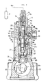
- Fig. 1 is a side view showing the first embodiment according to this invention.
- Fig. 2 is a side view of Fig. 1 seen from the arrow III,
- Fig. 3 is a sectional view of Fig. 1 taken along the line IV-IV and seen from the arrows,
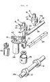
- Fig. 4 is an exploded perspective view showing important parts,
- Fig. 5 is an enlarged perspective view of the main parts of a
plunger 8 and acontrol sleeve 14, - Figs. 6 to 9 each are an operation illustrative view showing the operation of the
plunger 8 andcontrol sleeve 14 in their relative related position, - Fig. 10 is an operation illustrative view showing the pumping operation caused by the plunger,
- Fig. 11 is a sectional view of Fig. 1 taken along the line XII-XII and seen from the arrows,
- Fig. 12 is a sectional view of Fig. 11 taken along the line XIII-XIII and seen from the arrows,
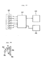
- Fig. 13 is a view of the actuating circuit for an
electromagnetic solenoid 44, - Fig. 14 is a front view showing a modification of a control groove cut on the outer peripheral surface of the plunger,
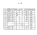
- Fig. 15 is a table representing the dimensions of the main parts of the fuel injection pumps used for the respective engine mechanisms,
- Fig. 16 is a graph showing the relation between the average oil feed ratio and (plunger diameter D)2xcam lift h,
- Fig. 17 is a graph showing the relation between the piston displacement per each cylinder of the engine and the geometrical average oil feed ratio, the
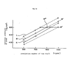
- Fig. 18 is a graph showing the relation between the revolution number of a cam shaft and the internal pressure on the pump side,
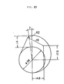
- Fig. 19 is a view of a cam profile,
- Fig. 20 is a cam diagram,
- Fig. 21 is a table showing the dimensions of the parts of the fuel injection pumps having performances designated by the points P, Q, R, S, T, and U in Fig. 17, and
- Fig. 22 is a characteristic diagram obtained in the first embodiment.
- In Fig. 1 to Fig. 22, the
reference numeral 2 represents a housing of an in-line fuel injection pump for a Diesel engine, and 4 represents one of a plurality of barrels in the housing, whichbarrels 4 are positioned so that their axes stand in rows on one plane in thehousing 2. Thisbarrel 4 is composed of afirst barrel part 4a and asecond barrel part 4b press-fitted thereon. Thereference numeral 6 represents a delivery valve holder fixed on the top of eachbarrel 4, which holder is to be connected to the respective cylinders of an engine; 7a is a delivery valve; 8 is a plunger slidably mounted in eachbarrel 4; 10 is a spring for biasing the plunger downwards; 12 is a cam interlocked with a driving shaft (not shown) of an engine to push up theplunger 8; 14 is a control sleeve slidably mounted on the outer periphery of theplunger 8; 16 is a guide pin fixed on eachbarrel 4 and engaged in aguide groove 17 of thecontrol sleeve 14 to restrain its turn; and 18 is a sleeve turnably supported on thebarrel 4 but non-turnably engaged with theplunger 8. Theplunger 8 has anoil passage 8a which communicates its upper end face and its peripheral side to each other,peripheral side openings 8b formed on the peripheral side in communication with theoil passage 8a, alongitudinal groove 8c cut on the peripheral side so as to continue to the opening 8b and to run along the axis of theplunger 8, and aninclined groove 8d intersecting thislongitudinal groove 8c and slanting to the plunger axis, wherein a control groove is formed by both thesegrooves oil feed ports 8b (which will be hereinafter called "the openings"). In thecontrol sleeve 14, on the other hand,control ports 14a are perforated to define a fuel injection end. The condition which is required to inject fuel when theplunger 8 makes a given effective stroke as shown in Fig. 6 will be stated below. Representing the vertical width or length of thecontrol sleeve 14 by the sign lo and the length including thelongitudinal groove 8c and the opening 8b by thesign 11, namely, it is required that the relation l0>l1 is satisfied. Representing the length between the upper edge of thecontrol port 14a and the upper end of thecontrol sleeve 14 by thesign 14 and the length between said upper edge of thecontrol port 14a and the upper end of thelongitudinal groove 8c by thesign 13, it is also required, as a condition for preventing the two-stage blasting of fuel at the injection end when theplunger 8 injects the fuel at the minimum effective stroke as shown in Fig. 7, that therelation 13>14 is satisfied. And, it is required as a condition that theplunger 8 is permitted to move up and down at the position where thecontrol port 14a confronts thelongitudinal groove 8c as shown in Fig. 8, this is a condition for determining no injection of fuel, that the relation l1>l2 is satisfied, representing the length between the lower edge of thecontrol port 14a and the lower end of thecontrol sleeve 14 by the sign I2. It is further required that therelation 11>14 is satisfied, as a condition that no injection of fuel can be positively realized even when thecontrol port 14a is blocked up at the lower edge of the opening 8b by theplunger 8, under the state of said no injection operation as shown in Fig. 9. In Fig. 3, thereference numeral 15 represents a fuel chamber for storing fuel fed from a feed pump (not shown), wherein the fuel is not leaked into acam shaft case 13, because theplunger 8 is inserted in the cylindricalsecond barrel part 4b, with an oil-tight state held between them. Thereference numeral 21 represents an oil feed opening through which lubricating oil is fed to thecam shaft case tappet 25 and slidably engaged in aguide groove 27 cut in thehousing 2. Although not illustrated in Fig. 4, thereference numeral 29 shown in Fig. 3 represents an adjustment screw (not shown in Fig. 4 and Fig. 11) screwed in a screw hole of anoperation shaft 26 mentioned below, wherein the fuel injection timing can be finely adjusted by relaxing thescrew 29 to rotate alever 28 properly. - When the
cam 12 is rotated one time by acam shaft 12a driven by the rotating force received from the driving shaft of the engine and theroller 25a of thetappet 25 is pressed by thecam 12, according to the abovementioned composition, theplunger 8 will be reciprocated upwards by a given lift or vertically at one stroke. - Now, the course from the state shown in Fig. 3 to the state in that the
plunger 8 is pressed by thecam 12 to pump out the fuel will be described here with reference to Fig. 10(a) to (e) [wherein thecontrol sleeve 14 shall be in a fixed position between the states (a) and (b)]. When the related position of theplunger 8 and thecontrol sleeve 14 is in the state shown in Fig. 10(a) or the opening 8b is not still blocked up completely by thecontrol sleeve 14, the fuel is not pumped out because a pressurizingchamber 20 and thefuel chamber 15 are in communication with each other. After the opening 8b is then blocked up by thecontrol sleeve 14 as shown in Fig. 10(c) via the state of Fig. 10(b), the pressurizingchamber 20 is interrupted from thefuel chamber 15 and pressurized by theplunger 8. This stroke of theplunger 8 which moves between the states (a) and (c) is called a prestroke. When theplunger 8 continues to rise as shown in Fig. 10(d) from the state of Fig. 10(c), the delivery pressure in the pressurizingchamber 20 overcomes the spring force of aspring 7b in thedelivery valve holder 6 and thedelivery valve 7a is opened so that high-pressure fuel is fed to an injection nozzle V through aninjection tube 6a. Thus, the fuel is being pumped out until theinclined groove 8d of theplunger 8 communicates with thecontrol port 14a as shown in Fig. 10(e). When theinclined groove 8d gets to face thecontrol port 14a as shown in Fig. 10(e), the pressurizingchamber 20 begins to communicates with thefuel chamber 15 by way of theoil passage 8a, opening 8b andlongitudinal groove 8c, and as a result, the pumping of fuel comes to an end. Since theinclined groove 8d extends on the outer periphery of theplunger 8 so as to slant with respect to its axis, as can be seen from Fig. 5, the confrontation time of theinclined groove 8d with thecontrol ports 14a of thecontrol sleeve 14 in the stroke of theplunger 8 can be changed by the turning displacement of theplunger 8 caused by thesleeve 18, whereby the fuel injection quantity in one stroke of theplunger 8 can be regulated. In addition, the displacement of thesleeve 18 in its turning direction is carried out by displacing arack 24 which engages with aball 22 secured on thesleeve 18 in its longitudinal direction. - So, it will be understood that the present invention is arranged such that the
length 14 between thecontrol sleeve 14 and thecontrol port 14a is set to be shorter than thelength 13 between the upper end of thelongitudinal groove 8c and thecontrol port 14a when theplunger 8 is in its upmost stroked position, as shown in Fig. 7. By this arrangement, the two-stage blasting of fuel can be prevented. - Also, this invention is arranged such that the
length 11 of thelongitudinal groove 8c in the direction of the plunger axis is set to be larger than thelength 12 between the lower end of thecontrol sleeve 14 and thecontrol port 14a, as shown in Fig. 8. By this arrangement, no injection of fuel can be achieved. - On the other hand, although JP-U-59 52175 is somewhat similar in its construction to this invention, it does not disclose nor suggest the above arrangement for preventing two-stage blasting of fuel.
- None of US―A―3 847 126 and EP-A-0 075 802 has a longitudinal groove such as the
longitudinal groove 8c of this invention. - US―A―2 813 523 relates to the distributor type fuel injection pump in which the plunger is slided in the axial direction simultaneously with its rotation and which is of a type different from this invention. The slots merely act to define the beginning and ending of injection. Thus, this patent does not suggest the arrangement and effect of this invention as described above.
- The fuel injection timing control mechanism will be described here. The control of the fuel injection timing is conducted by the sliding displacement of the
control sleeve 14 along theplunger 8, and this sliding displacment is carried out by means of anoperation shaft 26 supported in thehousing 2 so as to lie by the side of thecontrol sleeve 14 and having its axis on one straight line parallel to a plane on which theaforementioned barrels 4 stand in rows and perpendicular to the axis of theplunger 8, thelever 28 fixed on theoperation shaft 26 and extended from the operation sahft toward theplunger 8, and a notchedgroove 14b formed on the outer peripheral surface of thecontrol sleeve 14, which is engaged with the fore end of thelever 28 to interlock the turning displacement of thelever 28 around theoperation shaft 26 and the sliding displacement of thecontrol sleeve 14. The outer peripheral surface of thelever 28 at its end has such a curvature that it is always in contact with the inner peripheral surface of the notchedgroove 14b, without giving any play between them. As well shown in Fig. 11, thesupport part 26a of theoperation shaft 26 at each end is supported on thehousing 2 by way of abearing 30 having an outer diameter which is larger than an external dimension including theoperation shaft 26 andlever 28 in the direction of the diameter of theoperation shaft 26, with aplate 32 disposed between one end of thebearing 30 and thehousing 2. In addition, thereference numeral 34 represents a snap ring which serves to prevent thebearing 30 secured in thehousing 2 from slipping out of the housing, and 36 represents a positioning pin embedded in thebearing 30 and running through theplate 32 to engage with thehousing 2. The fixing of theoperation shaft 26 is conducted by mounting eachbarrel 4,plunger 8 and controlsleeve 14 within thehousing 2, and then inserting theoperation shaft 26 into thehousing 2 from its end. - The turning displacement of the
operation shaft 26 is conducted by means of anoperation lever 40 fixed on one end of theoperation shaft 26 and anelectromagnetic solenoid 44 supported on thehousing 2 by abracket 41, which turns theoperation lever 40 by way of aslider 42, as shown in Figs. 1, 2 and 4. In order to operate theelectromagnetic solenoid 44 with accuracy, apotentiometer 46 for measuring the turning displacement of theoperation lever 40 is further supported on thebracket 41. As shown in Fig. 13, acontrol unit 52 is composed so that various informations on the operating state of the engine from operatingstate information sources 50, for example an engine speed, degree of an accelerator pedal depression, temperature of cooling water, temperature of intake air, boost pressure of an air intake system and temperature of exhaust gas, and the information on the turning displacement of theoperation shaft 26 from thepotentiometer 46 are sent to the control unit and these informations are calculated synthetically, thereby to obtain a control of accurate injection timing. It is possible to adopt a differential transformer type sensor in place of thispotentiometer 26. In the aforementioned embodiment, it is also possible to turn theoperation lever 40 by a hydraulic cylinder in place of theelectromagnetic solenoid 44. - Furthermore, the
rack 24 constitutes a fuel injection quantity control member, and theoperation shaft 26,operation lever 40 andslider 42 constitute a fuel injection timing control member. A fuel injection control means is made up of a governor (the minimum-maximum type or the all-speed type) (not shown) for driving therack 24, thecontrol unit 52 and theelectromagnetic solenoid 44. - Since the pump has the aforementioned composition, it has such operational effects as mentioned below. By turning the
plunger 8 around its axis to change the relatively related position of thecontrol port 14a to theinclined groove 8d forming a part of the control groove, namely, the effective stroke of the plunger is changed whereby the fuel injection quantity can be regulated. By causing thelongitudinal groove 8c to accord with thecontrol port 14a, the state of no fuel injection can be achieved as shown in Fig. 8. And further, the turning displacement of theoperation shaft 26 having thelever 28 causes thecontrol sleeve 14 to displace in the direction of the plunger axis. Thus, the prestroke of the plunger is changed, whereby the injection timing can be adjusted. Since the sizes of the respective parts between the plunger and control sleeve are set so that the relations 10>11 [the expression (1)], 11>12 [the expression (2)], 11>14 [the expression (3)] and 13>14 [the expression (4)] may be satisfied, as have been illustrated in Figs. 6 to 9, the following conditions will be defined respectively: (a) the condition of enabling the injection of fuel in accordance with the expression (1); (b) the condition of ensuring no injection of fuel in accordance with the expression (2); (c) the condition of obstructing positively the fuel injection under the operating state of no injection in accordance with the expression (3); and (d) the condition of obstructing positively the two-stage blasting of fuel by causing the upper end of the longitudinal groove 8c to face into the fuel chamber 15 from the upper end of the control sleeve 14, even if the control port 14a is not in communication with the control groove when the plunger 8 is displaced up to the top dead center as shown in Fig. 7, in the case that the fuel is being injected at the minimum effective stroke of the plunger, in accordance with the expression (4). Therefore, accurate controls of the fuel injection quantity and injection timing can be realized, and the injection timing control can be effected in an electronic control mode because the injection timing is controllable by a small operating force. Because of no requirement of such a timer as used in a conventional device, it is possible to simplify the structure of this fuel injection pump device correspondingly. Furthermore, since the first embodiment has such a structure that theplunger 8 is oil- tightly inserted in the lower cylindrical portion of thesecond barrel part 4b, it is possible to avoid the flowing of the fuel in thefuel chamber 15 into thecam shaft case 13. In the use of a pump having such a structure that its discharge pressure or pump pressure is increased by modifying the profile of thecam 12 to make the cam lift larger, while keeping the diameter of the plunger shown in Fig. 3, or enlarging only the plunger diameter, with the cam lift kept as it is, it is easily enabled to use the pump under a pressure lower than its withstanding pressure, if an advancing operation (by the downward movement of the control sleeve 14) is carried out through the aforementioned injection timing control, when the pump pressure reaches near to the withstanding pressure of the pump, this is when the engine is in a high speed region. And, it is thereby possible to make larger the discharge pressure of the pump in the medium and low load regions of the engine, with obtaining various operational effects, for example of seeking the increase in the output power of the engine in the same regions. - As shown in Fig. 14, a modification of the control groove in the aforementioned embodiment may be a control
groove comprising openings 8b communicating with alongitudinal groove 8c, aninclined groove 8d and theoil passage 8a in the plunger. In this case, the inner diameter d1 of the control port is set to be larger than the distance do between both thegrooves - Referring to an injection pump having such a composition that the diameter of the
plunger 8 is 12 mm and the lift of the cam 12 (which has a cam profile shown in Fig. 19) is 14 mm, as shown at the point P in Fig. 17, and the cam diagram shown in Fig. 20 is obtained, by way of example, the operational effect thereof will be described. - As shown in Fig. 18, the relation between the revolution number of the cam shaft and the delivery pressure of the pump is represented by the graph M. Assuming that the limit of the withstanding pressure in use of the pump is 800 kg/cm2 at that time, the delivery pressure for fuel is increased by the
plunger 8 with the increase in the engine speed, when the cam angle shown in the cam diagram of Fig. 20 falls within therange 81 in the so-called medium and low engine speed regions wherein the revolution number of the cam shaft varies from 500 to about 900 r.p.m. When the revolution number of the cam shaft becomes about 900 r.p.m., the delivery pressure reaches the withstanding pressure in use of the pump. At about 900 r.p.m., or when the revolution number of the cam shaft reaches the point M"', thecontrol sleeve 14 is moved downward by a given distance along theplunger 8. Thus, the prestroke of theplunger 8 becomes short and as a result, fuel is injected with the speed constant directed in the direction of the arrow, or the cam angle falling within therange 62, as shown in Fig. 20. In the high speed region of the engine, therefore, fuel is supplied from the fuel injection pump to the engine at the constant and maximum delivery pressure M" regardless of the engine speed, as shown in Fig. 18. And at the same time, the injection timing is controlled so as to be advanced, whereby the fuel is injected into a combustion chamber at a proper time and mixed with air in said chamber for combustion. - The dimensions of the main parts of fuel injection pumps which have been already known in the market and used in various types of Diesel engines (injection pumps having such a structure that the injection timing is adjusted by a centrifugal auto-timer), are tabulated as shown in Fig. 15.
- Plotting the average oil feed ratios (mm3/deg) on the abscissa and the values of (plunger diameter)2xcam lift on the ordinate as to the types A to J from the table of Fig. 15, there is obtained the graph shown in Fig. 16. From the graph of Fig. 16, it will be seen that the related expression,

- As for the types A to J, by the way, the relation between the piston displacement Vs (1) per one engine cylinder and the geometrical average oil feed ratio Vp will be next discussed. These relations will be represented as shown in the graph of Fig. 17, from which it can be seen that the respective injection pumps are contained in the lower region under the straight line K. In other words, it will be said that any injection pump having such a structure that the average oil feed ratio or the delivery pressure is heightened to increase the fuel injection quantity per the unit angle of its cam does not exist in the upper region over the straight line K. This reason has some connection with the use of a centrifugal auto-timer for conducting the control of the injection timing in the conventional pumps of the types A to J. Namely, the reason is that each injection pump of the types A to J is set, as shown by the single-dotted chain line in the graph of Fig. 18, so that the delivery pressure of the pump reaches a state almost near to the limit of the withstanding pressure of the .pump itself, when an engine is being operated in the maximum speed region, and the injection timing control is conducted by changing the rotating phase of the cam shaft with respect to the crank angular phase of the engine gradually, when the engine is in the medium speed region. Accordingly, such conventional injection pumps could not be used in such a way that in the medium and low speed regions of the engine (corresponding to the revolution number of the cam shaft of 500-900 r.p.m), the delivery pressure is heightened to be in the region shown by the straight lines L, M and N, thereby to increase the output performance of the engine.
- When the injection timing control is conducted in the fuel injection pump according to the present embodiment, by the way, fuel is injected in the range of the cam angle θ3, as clarified from Fig. 20. At that time, the cam lift is lower than that in the range of the
cam angle 81 which is in an ordinary injection timing. Therefore, it is possible to prevent the pump delivery pressure from lowering or rising when the injection timing is advanced. - The relation of this injection timing control and the pump delivery pressure will be described in detail.
- A cam diagram which will be obtained by shaping the profile of the
cam 12 in a cam contour having the dimension shown in Fig. 19 and determining the lift thereof at 14 mm, is shown in Fig. 20. Setting the diameter of theplunger 8 at 12 mm, the geometrical average oil feed ratio Vp obtained in this connection is sought as follows: 24.5 as the point T when D=9.5 and h=11; and Vp
 21.5 as the point U when D=9.5 and h=9.6, respectively. The respective points P to U are arranged in the table of Fig. 21.
 - Thus, it is understood that if the cam lift is increased with respect to the plunger diameter, as compared with the table of Fig. 15, the average oil feed ratios Vp will be plotted in the upper portion over the straight line K, as shown in Fig. 17.
- In an in-line injection pump, in general, there is a certain limitation even in enlargement of the diameter of a plunger, because of a restriction in the arrangement interval of barrels each mounted on the plunger. If the plunger diameter is enlarged, the whole length of the injection pump will become longer, with its mounting on an engine made difficult. If the height of a pump housing mounted on an engine exceeds the upper end of the engine in a large extent, it will be undesirable from the angle of the engine's loading property. From this point of view, there is a limitation of the heightening of a cam lift. Furthermore, there are also limitations in increasing the foundation circle and cam lift of the
cam 12, because the position of fixing bolt holes in use for fixing the pump on an engine is restricted. - In order to determine the plunger diameter and cam lift which may be adaptable, in consideration of the planning conditions for these respective pumps, the average oil feed ratios Vp must fall within such a range (this is the obliquely lined portion in Fig. 17) that the related expression


- By means of the fuel injection pump according to the invention which has a plunger diameter and cam lift determined as mentioned above, the engine output can be increased because it acts as a fuel injection pump whose delivery pressure is high when the engine is in medium and low speed regions, and the engine can be operated under the optimum control because it is kept at the state of the maximum delivery pressure and its injection timing is advanced when the engine is in a high speed region. As shown in the graph of Fig. 22, furthermore, the fuel injection pump of this invention (by the solid line) is composed so that the injection time becomes shorter throughout the whole of the engine speed regions, as compared with the aforementioned conventional injection pumps (by the single-dotted chain line), and it has various operational effects such as an improvement in the rate of fuel consumption proportional to the injection time shortened and an improvement in the exhaust gas performance of the engine.
- In Fig. 18, the straight line L expresses the delivery pressure in the case of a pump having D=1.25 and h=14 and the straight line N that in the case of a pump having D=12 and h=13, respectively. In there cases, it is also possible to restrain the delivery pressure while the revolution number of the cam shaft reaches the point M", by conducting the advancing control. Although the abovementioned descriptions have been made as to the pump withstanding pressure of 800 kg/cm2, the pump withstanding pressure is not limited to the value. The delivery pressure has been made to accord almost with the pump withstanding pressure between the points M'" and M", but the prestroke of the pump may be controlled as a matter of course so that the delivery pressure is below its withstanding pressure.
- On this embodiment, furthermore, the cam has been used having the profile shown in Fig. 19. If the radius of the cam profile at the point R, is made large, there will be obtained a speed constant diagram in the form of such a trapezoid as shown by the double dotted chain line a-b-c-d in Fig. 20. In the case of this profile, the speed constant between the points b-c becomes almost constant (although not shown, the lift curve of this cam must be also changed). If an injection of fuel is carried out in the range of this cam angle, which connects the point R and point U, as shown in Fig. 17, and the plunger diameter D and cam lift h can be selected for adaptation so as to satisfy the related expression fuel particles injected into the combustion chamber will become small and they will be dispersed satisfactorily in the combustion chamber and burnt effectively here, because the average pressure of this injection is larger. And besides, the selection range for the injection timing (in particular the advance timing) will be widened, because the average injection pressure is large.
Claims (4)


Applications Claiming Priority (12)
| Application Number | Priority Date | Filing Date | Title |
|---|---|---|---|
| JP66995/84U | 1984-05-08 | ||
| JP1984066995U JPS60178359U (en) | 1984-05-08 | 1984-05-08 | fuel injection pump |
| JP59096240A JPS60240868A (en) | 1984-05-14 | 1984-05-14 | Method of regulating injection timing of fuel injection pump |
| JP96240/84 | 1984-05-14 | ||
| JP1984148821U JPH0415983Y2 (en) | 1984-10-01 | 1984-10-01 | |
| JP148824/84U | 1984-10-01 | ||
| JP148821/84U | 1984-10-01 | ||
| JP1984148824U JPH0417808Y2 (en) | 1984-10-01 | 1984-10-01 | |
| JP208569/84 | 1984-10-04 | ||
| JP20856984A JPS6185572A (en) | 1984-10-04 | 1984-10-04 | Injection timing adjusting method of fuel injection pump |
| JP60225/85 | 1985-03-25 | ||
| JP60060225A JPH0635863B2 (en) | 1985-03-25 | 1985-03-25 | Fuel injection pump |
Publications (3)
| Publication Number | Publication Date |
|---|---|
| EP0181402A1 EP0181402A1 (en) | 1986-05-21 |
| EP0181402A4 EP0181402A4 (en) | 1986-09-22 |
| EP0181402B1 true EP0181402B1 (en) | 1990-05-30 |
Family
ID=27550780
Family Applications (1)
| Application Number | Title | Priority Date | Filing Date |
|---|---|---|---|
| EP85901582A Expired EP0181402B1 (en) | 1984-05-08 | 1985-03-29 | Fuel injection pump |
Country Status (6)
| Country | Link |
|---|---|
| US (1) | US4754737A (en) |
| EP (1) | EP0181402B1 (en) |
| AU (1) | AU563901B2 (en) |
| DE (1) | DE3590194C2 (en) |
| GB (1) | GB2167814B (en) |
| WO (1) | WO1985005152A1 (en) |
Cited By (2)
| Publication number | Priority date | Publication date | Assignee | Title |
|---|---|---|---|---|
| DE4041656A1 (en) * | 1990-12-22 | 1992-07-02 | Bosch Gmbh Robert | FUEL INJECTION PUMP FOR INTERNAL COMBUSTION ENGINES |
| DE4041503C2 (en) * | 1990-12-22 | 2001-02-15 | Bosch Gmbh Robert | Fuel injection pump for internal combustion engines |
Families Citing this family (36)
| Publication number | Priority date | Publication date | Assignee | Title |
|---|---|---|---|---|
| JPS61123756A (en) * | 1984-11-16 | 1986-06-11 | Diesel Kiki Co Ltd | Fuel injection pump |
| DE3522451A1 (en) * | 1985-06-22 | 1987-01-02 | Bosch Gmbh Robert | FUEL INJECTION PUMP FOR INTERNAL COMBUSTION ENGINES |
| DE3546222A1 (en) * | 1985-12-27 | 1987-07-02 | Bosch Gmbh Robert | FUEL INJECTION PUMP FOR INTERNAL COMBUSTION ENGINES |
| WO1987005665A1 (en) * | 1986-03-22 | 1987-09-24 | Robert Bosch Gmbh | Fuel injection pump for internal combustion engines |
| DE3609761A1 (en) * | 1986-03-22 | 1987-09-24 | Bosch Gmbh Robert | Fuel injection pump for internal combustion engines |
| DE3630647A1 (en) * | 1986-03-24 | 1988-02-11 | Bosch Gmbh Robert | FUEL INJECTION PUMP FOR INTERNAL COMBUSTION ENGINES |
| DE3707646A1 (en) * | 1986-03-24 | 1987-10-08 | Bosch Gmbh Robert | FUEL INJECTION PUMP FOR INTERNAL COMBUSTION ENGINES |
| GB2189846B (en) * | 1986-04-28 | 1989-11-29 | Diesel Kiki Co | Fuel injection pump |
| DE3633899A1 (en) * | 1986-10-04 | 1988-04-07 | Bosch Gmbh Robert | FUEL INJECTION PUMP FOR INTERNAL COMBUSTION ENGINES |
| DE3724409A1 (en) * | 1986-10-31 | 1988-05-19 | Bosch Gmbh Robert | FUEL INJECTION PUMP FOR INTERNAL COMBUSTION ENGINES |
| DE3736091A1 (en) * | 1987-10-24 | 1989-05-03 | Bosch Gmbh Robert | FUEL INJECTION PUMP FOR INTERNAL COMBUSTION ENGINES |
| US5080564A (en) * | 1989-02-08 | 1992-01-14 | Diesel Kiki Co., Ltd. | Prestroke control device for fuel injection pumps |
| EP0469142B1 (en) * | 1990-02-21 | 1995-04-05 | Robert Bosch Ag | Fuel injection device for fuel-injected internal combustion engines |
| JP2543729Y2 (en) * | 1990-09-13 | 1997-08-13 | 三菱自動車工業株式会社 | Diesel engine fuel injection system |
| US5266014A (en) * | 1991-03-11 | 1993-11-30 | Zexel Corporation | Prestroke adjustment mechanism for fuel injection pump |
| DE4132502C2 (en) * | 1991-09-30 | 2001-09-27 | Bosch Gmbh Robert | Fuel injection pump |
| DE4132505A1 (en) * | 1991-09-30 | 1993-04-01 | Bosch Gmbh Robert | FUEL INJECTION PUMP FOR INTERNAL COMBUSTION ENGINES |
| JP3440347B2 (en) * | 1994-07-27 | 2003-08-25 | 株式会社ボッシュオートモーティブシステム | Pre-stroke control device for fuel injection pump |
| JPH08100740A (en) * | 1994-09-30 | 1996-04-16 | Zexel Corp | Pilot injection amount control mechanism of fuel injection device and pilot injection amount control method |
| JP3666085B2 (en) * | 1995-12-06 | 2005-06-29 | いすゞ自動車株式会社 | Fuel injection pump |
| DE19734196A1 (en) | 1997-08-07 | 1999-02-11 | Hatz Motoren | Control device and method for its production |
| GB9826756D0 (en) * | 1998-12-05 | 1999-01-27 | Lucas Ind Plc | Governor |
| EP1143138A1 (en) | 2000-04-03 | 2001-10-10 | Wärtsilä NSD Schweiz AG | Fuel injection pump |
| CN1982690B (en) * | 2000-05-26 | 2012-03-21 | 洋马株式会社 | Fuel injection pump |
| DE10059386A1 (en) * | 2000-11-30 | 2002-06-13 | Aixtron Ag | Method and device for the metered delivery of small liquid volume flows |
| US7077101B2 (en) * | 2002-08-14 | 2006-07-18 | Electro-Motive Diesel, Inc. | Hybrid fuel injection system |
| US7513756B2 (en) * | 2002-10-29 | 2009-04-07 | Bosch Automotive Systems Corporation | Fuel supply pump and tappet structure body |
| JP3993841B2 (en) * | 2003-06-12 | 2007-10-17 | ヤンマー株式会社 | Fuel injection pump having a cold start advancement mechanism |
| US7412971B2 (en) * | 2005-01-27 | 2008-08-19 | Advanced Global Equities And Intellectual Properties, Inc. | Selectively detachable helix ring for a fuel injector |
| DE102005050233A1 (en) * | 2005-10-20 | 2007-04-26 | Daimlerchrysler Ag | Plug pump injection system |
| CN102364081A (en) * | 2011-11-09 | 2012-02-29 | 王晓燕 | Plunger type single oil supply pump |
| JP5459329B2 (en) * | 2012-01-31 | 2014-04-02 | 株式会社デンソー | Supply pump |
| WO2016105355A1 (en) * | 2014-12-23 | 2016-06-30 | Cummins Inc. | Tappet roller retaining approach |
| GB201505089D0 (en) * | 2015-03-26 | 2015-05-06 | Delphi International Operations Luxembourg S.�.R.L. | An oil lubricated common rail diesel pump |
| US10677210B2 (en) * | 2017-11-30 | 2020-06-09 | Cfr Engines Canada Ulc | Air-assisted fuel injection system for ignition quality determination |
| JP7120081B2 (en) * | 2019-03-01 | 2022-08-17 | 株式会社デンソー | fuel injection pump |
Family Cites Families (29)
| Publication number | Priority date | Publication date | Assignee | Title |
|---|---|---|---|---|
| GB162592A (en) * | 1920-09-18 | 1921-05-05 | Hermann Stubner | Improvements in or relating to wooden soles |
| FR677993A (en) * | 1928-08-13 | 1930-03-17 | Control for distributors moving with a constant amplitude reciprocating movement | |
| US2147390A (en) * | 1934-04-17 | 1939-02-14 | Provencale De Const Aeronautiq | Fuel feed pump |
| FR833992A (en) * | 1937-02-18 | 1938-11-08 | Provencale De Const Aeronautiq | Improvements made to fuel injection pumps, in particular to those with several bodies |
| DE705407C (en) * | 1938-07-31 | 1941-04-26 | Bosch Gmbh Robert | Device for the individual adjustment of the individual pumps of a multi-cylinder injection pump |
| US2540755A (en) * | 1947-06-25 | 1951-02-06 | United Aireraft Corp | Fuel injection system and apparatus |
| GB679006A (en) * | 1951-02-26 | 1952-09-10 | Victor Silberstein | Improvements in fuel-injection pumps |
| US2759422A (en) * | 1951-12-13 | 1956-08-21 | Bosch Arma Corp | Fuel injection apparatus |
| US2813523A (en) * | 1953-10-29 | 1957-11-19 | Bosch Arma Corp | Fuel injection pump |
| JPS5339528B1 (en) * | 1971-03-06 | 1978-10-21 | ||
| JPS5242269Y2 (en) * | 1971-11-25 | 1977-09-26 | ||
| US3847126A (en) * | 1973-10-01 | 1974-11-12 | Allis Chalmers | Injection timing modulator |
| US3999529A (en) * | 1975-05-19 | 1976-12-28 | Stanadyne, Inc. | Multiple plunger fuel injection pump |
| JPS5242269A (en) * | 1975-09-30 | 1977-04-01 | Matsushita Electric Works Ltd | 22pole one element type circuit breaker |
| JPS55164773A (en) * | 1979-06-11 | 1980-12-22 | Diesel Kiki Co Ltd | Fuel injection device for internal combustion engine |
| JPS56152456A (en) * | 1980-04-28 | 1981-11-26 | Mitsui Petrochem Ind Ltd | Preparation of hydroperoxide |
| DE3017730A1 (en) * | 1980-05-09 | 1981-11-12 | Robert Bosch Gmbh, 7000 Stuttgart | FUEL INJECTION PUMP FOR INTERNAL COMBUSTION ENGINES |
| DE3048205A1 (en) * | 1980-12-20 | 1982-07-29 | Robert Bosch Gmbh, 7000 Stuttgart | DEVICE FOR ADJUSTING THE FLOW RATE OF THE PUMP ELEMENTS OF FUEL INJECTION PUMPS |
| JPS57142167A (en) * | 1981-02-25 | 1982-09-02 | Matsushita Electric Ind Co Ltd | Hollow cylindrical core armature for dc motor |
| JPS57152456U (en) * | 1981-03-19 | 1982-09-24 | ||
| JPS5853646A (en) * | 1981-09-24 | 1983-03-30 | Hitachi Ltd | Controller of fuel injection pump |
| DE3143073A1 (en) * | 1981-10-30 | 1983-05-11 | Robert Bosch Gmbh, 7000 Stuttgart | INJECTION PUMP WITH ADJUSTABLE SPRAYING POINT |
| FR2523217A1 (en) * | 1982-03-09 | 1983-09-16 | France Etat | Engine injection pump port closing detector - uses constant pressure gas supply connected to discharge union by control gate |
| JPS58167770A (en) * | 1982-03-29 | 1983-10-04 | Toshiba Corp | Preparation of shadow mask |
| JPS58167770U (en) * | 1982-04-30 | 1983-11-09 | ヤンマーディーゼル株式会社 | Fuel injection pump for internal combustion engines |
| JPS5952175A (en) * | 1982-09-17 | 1984-03-26 | 三菱電機株式会社 | Cooling device |
| JPS5952175U (en) | 1982-09-30 | 1984-04-05 | 三菱自動車工業株式会社 | injection pump |
| GB2128267A (en) * | 1982-10-08 | 1984-04-26 | Lucas Ind Plc | Fuel injection pumping apparatus |
| JPS61123756A (en) * | 1984-11-16 | 1986-06-11 | Diesel Kiki Co Ltd | Fuel injection pump |
-
1985
- 1985-03-29 WO PCT/JP1985/000153 patent/WO1985005152A1/en not_active Ceased
- 1985-03-29 US US06/823,482 patent/US4754737A/en not_active Expired - Lifetime
- 1985-03-29 AU AU41546/85A patent/AU563901B2/en not_active Expired
- 1985-03-29 EP EP85901582A patent/EP0181402B1/en not_active Expired
- 1985-03-29 DE DE3590194A patent/DE3590194C2/en not_active Expired - Lifetime
- 1985-03-29 GB GB08531107A patent/GB2167814B/en not_active Expired
Cited By (2)
| Publication number | Priority date | Publication date | Assignee | Title |
|---|---|---|---|---|
| DE4041656A1 (en) * | 1990-12-22 | 1992-07-02 | Bosch Gmbh Robert | FUEL INJECTION PUMP FOR INTERNAL COMBUSTION ENGINES |
| DE4041503C2 (en) * | 1990-12-22 | 2001-02-15 | Bosch Gmbh Robert | Fuel injection pump for internal combustion engines |
Also Published As
| Publication number | Publication date |
|---|---|
| AU563901B2 (en) | 1987-07-23 |
| GB2167814A (en) | 1986-06-04 |
| EP0181402A1 (en) | 1986-05-21 |
| AU4154685A (en) | 1985-11-28 |
| EP0181402A4 (en) | 1986-09-22 |
| WO1985005152A1 (en) | 1985-11-21 |
| GB2167814B (en) | 1988-10-19 |
| US4754737A (en) | 1988-07-05 |
| DE3590194C2 (en) | 1996-03-28 |
| GB8531107D0 (en) | 1986-01-29 |
Similar Documents
| Publication | Publication Date | Title |
|---|---|---|
| US4754737A (en) | Fuel injection pump device and method for settling the same | |
| JP2843614B2 (en) | Two-cycle diesel engine | |
| WO1983000901A1 (en) | Method of controlling the combustion cycle in a combustion engine, and a combustion engine | |
| US4881506A (en) | Injection pump with preinjection | |
| US5592915A (en) | Pilot injection controller in fuel injection system and method of controlling pilot injection quantity | |
| US5271366A (en) | Fuel injection system | |
| US4476835A (en) | Method for delaying axial movement of a pump piston in a fuel _injection pump for combustion engines, and fuel injection pump for _completing the process | |
| US4696271A (en) | Fuel injection pump | |
| US4630586A (en) | Fuel injection pump for internal combustion engines | |
| US4083662A (en) | Fuel injection pump for internal combustion engine | |
| US5911207A (en) | Fuel injection pump | |
| US4763631A (en) | Fuel injection pump for internal combustion engines | |
| US5123393A (en) | Timing control system for fuel injection pump | |
| US6082335A (en) | Fuel injection pump for internal combustion engines, in particular one-cylinder diesel engines | |
| US4924833A (en) | Fuel-injection pump for an internal-combustion engine | |
| EP0512458A1 (en) | Fuel injection pump | |
| GB2163492A (en) | Fuel injection pump for internal combustion engines | |
| US5243943A (en) | Fuel injection pump | |
| JP2808475B2 (en) | Fuel injection pump | |
| JPH0421004Y2 (en) | ||
| JPH0635863B2 (en) | Fuel injection pump | |
| JPH021485Y2 (en) | ||
| JP3147506B2 (en) | Fuel injection device | |
| CA1049845A (en) | Fuel pumping apparatus | |
| JP3132082B2 (en) | Distribution type fuel injection pump |
Legal Events
| Date | Code | Title | Description |
|---|---|---|---|
| PUAI | Public reference made under article 153(3) epc to a published international application that has entered the european phase |
Free format text: ORIGINAL CODE: 0009012 |
|
| 17P | Request for examination filed |
Effective date: 19860116 |
|
| AK | Designated contracting states |
Kind code of ref document: A1 Designated state(s): FR |
|
| A4 | Supplementary search report drawn up and despatched |
Effective date: 19860922 |
|
| 17Q | First examination report despatched |
Effective date: 19870421 |
|
| RAP1 | Party data changed (applicant data changed or rights of an application transferred) |
Owner name: DIESEL KIKI CO., LTD. Owner name: MITSUBISHI JIDOSHA KOGYO KABUSHIKI KAISHA |
|
| GRAA | (expected) grant |
Free format text: ORIGINAL CODE: 0009210 |
|
| AK | Designated contracting states |
Kind code of ref document: B1 Designated state(s): FR |
|
| ET | Fr: translation filed | ||
| PLBI | Opposition filed |
Free format text: ORIGINAL CODE: 0009260 |
|
| 26 | Opposition filed |
Opponent name: ROBERT BOSCH GMBH Effective date: 19910228 |
|
| PLBN | Opposition rejected |
Free format text: ORIGINAL CODE: 0009273 |
|
| STAA | Information on the status of an ep patent application or granted ep patent |
Free format text: STATUS: OPPOSITION REJECTED |
|
| 27O | Opposition rejected |
Effective date: 19920615 |
|
| REG | Reference to a national code |
Ref country code: FR Ref legal event code: CA Ref country code: FR Ref legal event code: CD |
|
| REG | Reference to a national code |
Ref country code: FR Ref legal event code: TQ |
|
| PGFP | Annual fee paid to national office [announced via postgrant information from national office to epo] |
Ref country code: FR Payment date: 20040309 Year of fee payment: 20 |
|
| REG | Reference to a national code |
Ref country code: FR Ref legal event code: CA |
|
| APAH | Appeal reference modified |
Free format text: ORIGINAL CODE: EPIDOSCREFNO |