EP0181237B1 - Unité de traitement à prédiction adaptative pour signaux d'images numériques - Google Patents
Unité de traitement à prédiction adaptative pour signaux d'images numériques Download PDFInfo
- Publication number
- EP0181237B1 EP0181237B1 EP85308187A EP85308187A EP0181237B1 EP 0181237 B1 EP0181237 B1 EP 0181237B1 EP 85308187 A EP85308187 A EP 85308187A EP 85308187 A EP85308187 A EP 85308187A EP 0181237 B1 EP0181237 B1 EP 0181237B1
- Authority
- EP
- European Patent Office
- Prior art keywords
- prediction
- signal
- inframe
- background
- local
- Prior art date
- Legal status (The legal status is an assumption and is not a legal conclusion. Google has not performed a legal analysis and makes no representation as to the accuracy of the status listed.)
- Expired - Lifetime
Links
Images


Classifications
-
- H—ELECTRICITY
- H04—ELECTRIC COMMUNICATION TECHNIQUE
- H04N—PICTORIAL COMMUNICATION, e.g. TELEVISION
- H04N19/00—Methods or arrangements for coding, decoding, compressing or decompressing digital video signals
- H04N19/50—Methods or arrangements for coding, decoding, compressing or decompressing digital video signals using predictive coding
- H04N19/503—Methods or arrangements for coding, decoding, compressing or decompressing digital video signals using predictive coding involving temporal prediction
Definitions
- This invention relates to a signal processing unit for use in a digital transmission system, such as a closed-circuit television system.
- a succession of picture data is transmitted to convey television pictures from a transmitting end to a receiving end.
- the pictures are represented by a time sequence of a large number of picture elements.
- each of the transmitting and the receiving ends comprises a signal processing unit.
- the signal processing unit of the transmitting end is for producing a prediction signal predictive of the picture data succession.
- a conventional signal processing unit comprises two prediction circuits and a selection circuit coupled to the prediction circuits in the manner which will later be described more in detail.
- One of the two prediction circuits is an interframe prediction circuit for predicting each frame of the picture data succession by a preceding frame to produce an interframe prediction signal.
- the other prediction circuit is herein called an additional prediction circuit.
- the additional prediction circuit predicts a part of the picture data succession to produce an additional prediction signal by an additional part which appears in the picture data succession at another instant previous to the current instant.
- the selection circuit is for selecting one of the interframe and the additional prediction signals as that part of the prediction signal which should be used at the current instant.
- a first group of the picture elements is representative of a stationary area, namely, a background.
- a second group of the picture elements is representative of a movable object, such as a person who is participating in a conference.
- a third group of the picture elements is representative of, for example, that part of the background which become visible as a result of movement of the movable object.
- the conventional signal processing unit is incapable of appropriately predicting the picture data signal. This is because the additional prediction signal is only predictive of either the first group of the picture elements or the second group.
- Another known signal processing unit is disclosed in US-A-4,437,119 and comprises a median selector and an optimum prediction circuit.
- the median selector compares prediction values of intra-field, inter-field, and inter-frame predictions with one another to select, as a median value, a prediction value corresponding to a median.
- the optimum prediction circuit carries out prediction of a current picture element in a current instant on the basis of the intra-field, inter-field, and inter-frame predictions with reference to a previous picture element in a previous instant preceding the current instant and selects, as an optimum value, the smallest value of the prediction errors.
- the optimum value is selected as a prediction value close to the true value. Otherwise, a weighted mean value of the median and the optimum values is employed.
- the prediction value or the weighted mean value may not always be optimum because it will be assumed that the median value is selected as the prediction value when the moving and the stationary parts are not clearly distinguished in the picture. Therefore, the result of the prediction has a low reliability. Thus, the prediction value is determined in dependency upon the moving and the stationary parts.
- the picture 10 shows a stationary area 12 and a movable object 14.
- the movable object is a person who is participating in a conference.
- the stationary area 12 represents a background of the movable object 14.
- a new background 18 becomes visible as a part of the background 12 in the manner depicted right to the movable object 14.
- the signal processing unit comprises a quantizer 21, an inframe or intraframe prediction circuit 22, an interframe prediction circuit 23, a selection circuit 24, a subtractor 26, and an adder 27 in the manner which will presently become clear.
- a succession of picture data is supplied to the subtractor 26 as an original signal through an input terminal 28.
- a prediction signal is also supplied to the subtractor 26 from the selection circuit 24.
- the subtractor 26 subtracts the prediction signal from the original signal.
- a result of subtraction is produced as a differential signal from the subtractor 26.
- the differential signal is supplied to the quantizer 21.
- the quantizer 21 is for quantizing the differential signal into a quantized signal.
- the quantized signal is transmitted as a succession of coded data from an output terminal 29.
- the quantized and the prediction signals are supplied to the adder 27 and are added together. A result of addition is produced as a local signal from the adder 27. It will be understood that the local signal is similar to the original signal and may therefore be referred to also as an original.
- the local signal is supplied to the inframe prediction, the interframe prediction, and the selection circuits 22, 23, and 24.
- the inframe and the interframe prediction circuits 22 and 23 are for delivering inframe and interframe prediction signals to the selection circuit 24.
- the inframe and interframe prediction signals which appear at the current instant may be referred to as first and second prediction parts derived with reference to first and second parts appearing in the original signal at first and second instants which precede the current instant.
- the selection circuit 24 is responsive to the local, the inframe prediction, and the interframe prediction signals for selecting one of the inframe and the interframe prediction signals to produce the prediction signal.
- a selection rule is used in the selection circuit 24 in regard to picture elements Sx and Sa to Sd depicted at the top of the picture.
- the picture element Sx is for prediction at the current instant and is herein called the current picture element.
- Each of the other picture elements Sa to Sd is adjacent to the current picture element Sx and hence is herein called an adjacent picture element.
- the adjacent picture elements Sa to Sd are already predictively selected by the selection circuit 24.
- the result of selection of the adjacent picture elements Sa to Sd is represented by logic “1” or “0” in the figure with the current picture element shown by a cross.
- the logic “1” indicates that the interframe prediction signal has been selected by the selection circuit 24.
- the logic "0” indicates that the inframe prediction signal has been selected by the selection circuit 24.
- the current picture element Sx is calculated by a predetermined expression which will generally be given as follows:
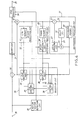
- a predictive encoder comprises a signal processing unit according to a first embodiment of this invention.
- the signal processing unit comprises similar parts designated by like reference numerals.
- the signal processing unit further comprises a background prediction circuit 31, a motion vector detection circuit 33, and a code converter 34.
- the selection circuit 24 comprises a first selecting part 36, a second selecting part 37, a first control circuit 38, and a second control circuit 39.
- the inframe prediction circuit 22 includes a line memory 41.
- the line memory 41 is capable of temporarily memorizing the local signal for producing the inframe prediction signal.
- a first delay time is determined for delaying the local signal.
- the first delay time corresponds to a single line which comprises a plurality of picture elements. Alternatively, the first delay time may be a time interval between two adjacent picture elements. From the line memory 41, the local signal is delivered as the inframe prediction signal to the second control circuit 39 and the second selecting part 37.
- the interframe prediction circuit 23 includes a frame memory 43 and a delay adjusting circuit 44.
- the frame memory 43 is capable of memorizing the local signal.
- a second delay time is determined for delaying the local signal.
- the second delay time corresponds to a single frame which comprises a plurality of lines.
- the local signal is sent from the frame memory 43 to the delay adjusting circuit 44.
- the delay adjusting circuit 44 the second delay time is adjusted in response to a motion vector signal sent from the motion vector detection circuit 33 in the manner which will presently be described.
- the interframe prediction signal is motion- compensated.
- the background prediction circuit 31 comprises a local subtractor 51, a local comparing circuit 52, a local adder 53, a delay circuit 54, and a background memory 55.
- the local subtractor 51 subtracts that preceding background signal from the local signal which is sent from the background memory 55 through a line 56.
- the result of the subtraction is produced as a local differential signal from the local subtractor 51.
- the local differential signal is supplied to the local comparing circuit 52.
- the absolute value of the local differential signal is compared with a predetermined threshold value in the local comparing circuit 52. When the absolute value of the local differential signal is lowerthan the predetermined threshold value, zero is sent to the local adder 53 as a predetermined value. Otherwise, the local differential signal is supplied as a modified differential signal to the local adder 53.
- the local adder 53 adds the modified differential signal to the preceding background signal which is supplied from the delay circuit 55 through a line 57.
- the result of the addition is produced as a background prediction signal from the local adder 53 and is supplied to the first selecting part 36, the first control circuit 38, and the background memory 55.
- the background memory 55 is capable of memorizing the single frame of the background prediction signal.
- a third delay time is determined for delaying the background predictive signal.
- the third delay time corresponds to the single frame.
- the background prediction signal is supplied as the preceding background signal from the background memory 55 to the local subtractor 51 and the delay circuit 54.
- the delay circuit 54 is for delaying the background prediction signal in response to the local comparing circuit 52.
- Operation of the local comparing circuit 52 may be controlled by the motion vector signal derived from the motion vector detection cicuit 33. More particularly, the local comparing circuit 52 may be designed so as to produce the predetermined value of zero in the absence of the motion vector signal irrespective of production or not of the local differential signal.
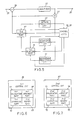
- the first control circuit 38 comprises a first calculation part 61, a first comparing part 62, a first memory part 63, and a first judgment part 64.
- the first calculation part 61 is responsive to the local, the inter- frame prediction, and the background prediction signals and is for subtracting the local signal from each of the interframe and the background prediction signals to produce a first and a second prediction error signal. Absolute values of the first and the second prediction error signals are compared with each other in the first comparing part 62. The smaller one of the first and the second prediction error signals is selected as a first selection or control signal by the first comparing part 62 and is memorized in the first memory part 63.
- a first judgment is carried out in the first judgment part 64 by using the first and the second prediction error signals which are memorized in the first memory part 63.
- the first judgment is for selecting a preferable one of the interframe and the background prediction signals to produce a local prediction signal.
- the rule for the first judgment may be similar to the selection rule described with reference to Fig. 3.
- the local prediction signal is supplied to the second control circuit 39.
- the first prediction signal is sent to the first selecting part 36.
- the first selecting part 36 is responsive to the first selection signal and is for selecting one of the interframe and the background prediction signals to produce a selected prediction signal which is equal to the local prediction signal.
- the local prediction signal is supplied to the second selecting part 37.
- the second control circuit 39 comprises a second calculation part 71, a second comparing part 72, a second memory part 73, and a second judgment part 74.
- the second calculation part 71 is responsive to the local, the inframe prediction, and the local prediction signals and is for subtracting the local signal from each of the inframe and the local prediction signals to produce a third and a fourth prediction error signal. Absolute values of the third and the fourth prediction error signals are compared with each other in the second comparing part 72. A smaller one of the third and the fourth prediction error signals is selected as a second selection or control signal by the second comparing part 72 and is memorized in the second memory part 73.
- a second judgment is carried out in the second judgment part 74 by using the third and the fourth prediction error signals which are memorized in the second memory part 73.
- the second judgment is for selecting a preferable one of the inframe and the local prediction signals.
- a rule for the second judgment may also be similar to the selection rule described with reference to Fig. 3.
- the second selection signal is sent to the second selecting part 37.
- the second selecting part 37 is responsive to the second selection signal and is for selecting one of the inframe and the selected prediction signals to produce the prediction signal.
- a combination of the first and the second control circuits 38 and 39 serves as a comparing circuit for comparing the inframe, the interframe, and the background prediction signals with a current part of the local signal at each current instant.
- the prediction signal is supplied to the subtractor 26 and the adder 27 in the manner described with reference to Fig. 2.
- the quantized and the motion vector signals are supplied to the code converter 34.
- the code converter 34 is for processing the quantized and the motion vector signals to produce an output signal of, for example, a Huffman code.
- the output signal is transmitted as a succession of coded data from the output terminal 29.
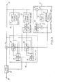
- a predictive decoder comprises a signal processing unit according to a second embodiment of this invention.
- the signal processing unit comprises similar parts designated by like reference numerals.
- the signal processing unit further comprises a code converter 81 and an adder 82.
- a succession of picture data is supplied to the code converter 81 through the input terminal 28 as an input signal.
- the picture data succession may be the coded data succession which is transmitted from the predictive encoder illustrated in Fig. 4.
- the code converter 81 is for processing the input signal to produce the motion vector signal and a converted local signal which is similar to the quantized signal described before.
- the motion vector signal is supplied to the delay adjusting circuit 44 for adjusting the second delay time of the frame memory 43.
- the converted local signal is supplied to the adder 82.
- the prediction signal is also supplied to the adder 82 from the second selecting part 37.
- the adder 82 adds the converted local signal to the prediction signal.
- the result of addition is produced from the adder 82 as a decoded signal which is similar to the above-described original signal and may therefore be referred to also as an original.
- the decoded signal is supplied to the inframe prediction, the interframe prediction, the background prediction, the first control, and the second control circuits 22, 23, 31, 38, and 39.
- the decoded signal is also sent out as a succession of decoded data from the output terminal 29.
- the selection rules used in the selection circuit 24 may be combined together so as to estimate efficiency about the inframe, the interframe, and the background predictions and to give grades from a high efficiency. Under the circumstances, one of the predictions may be determined one time by comparing the grades of the picture elements which are already predicted and adjacent to a current picture element.
Landscapes
- Engineering & Computer Science (AREA)
- Multimedia (AREA)
- Signal Processing (AREA)
- Compression Or Coding Systems Of Tv Signals (AREA)
Claims (4)
Applications Claiming Priority (2)
| Application Number | Priority Date | Filing Date | Title |
|---|---|---|---|
| JP59236227A JPS61114677A (ja) | 1984-11-09 | 1984-11-09 | 動画像信号の適応予測符号化復号化方式及びその装置 |
| JP236227/84 | 1984-11-09 |
Publications (3)
| Publication Number | Publication Date |
|---|---|
| EP0181237A2 EP0181237A2 (fr) | 1986-05-14 |
| EP0181237A3 EP0181237A3 (en) | 1987-07-15 |
| EP0181237B1 true EP0181237B1 (fr) | 1991-01-23 |
Family
ID=16997671
Family Applications (1)
| Application Number | Title | Priority Date | Filing Date |
|---|---|---|---|
| EP85308187A Expired - Lifetime EP0181237B1 (fr) | 1984-11-09 | 1985-11-11 | Unité de traitement à prédiction adaptative pour signaux d'images numériques |
Country Status (6)
| Country | Link |
|---|---|
| US (1) | US4802006A (fr) |
| EP (1) | EP0181237B1 (fr) |
| JP (1) | JPS61114677A (fr) |
| AU (1) | AU579681B2 (fr) |
| CA (1) | CA1238408A (fr) |
| DE (1) | DE3581489D1 (fr) |
Families Citing this family (30)
| Publication number | Priority date | Publication date | Assignee | Title |
|---|---|---|---|---|
| JPS61114676A (ja) * | 1984-11-09 | 1986-06-02 | Nec Corp | ブロツク符号化装置 |
| JPS61118085A (ja) * | 1984-11-14 | 1986-06-05 | Nec Corp | 画像信号の符号化方式およびその装置 |
| AU579441B2 (en) * | 1985-01-16 | 1988-11-24 | Mitsubishi Denki Kabushiki Kaisha | Video encoding apparatus |
| US4779131A (en) * | 1985-07-26 | 1988-10-18 | Sony Corporation | Apparatus for detecting television image movement |
| JPS62214792A (ja) * | 1986-03-14 | 1987-09-21 | Fujitsu Ltd | 差分符号化装置 |
| NL8700565A (nl) * | 1987-03-10 | 1988-10-03 | Philips Nv | Televisiesysteem waarin aan een transformatiekodering onderworpen gedigitaliseerde beeldsignalen worden overgebracht van een kodeerstation naar een dekodeerstation. |
| JP2801911B2 (ja) * | 1987-10-16 | 1998-09-21 | 日本電気ホームエレクトロニクス 株式会社 | 予測符号化による画像データの圧縮装置 |
| DE3811535A1 (de) * | 1988-04-06 | 1989-10-19 | Philips Patentverwaltung | Hybrid-codierer fuer videosignale |
| US4953023A (en) * | 1988-09-29 | 1990-08-28 | Sony Corporation | Coding apparatus for encoding and compressing video data |
| US4891699A (en) * | 1989-02-23 | 1990-01-02 | Matsushita Electric Industrial Co., Ltd. | Receiving system for band-compression image signal |
| JP3159309B2 (ja) * | 1989-09-27 | 2001-04-23 | ソニー株式会社 | 映像信号符号化方法及び映像信号符号化装置 |
| NL8902612A (nl) * | 1989-10-23 | 1991-05-16 | Philips Nv | Werkwijze voor het overzenden van een digitaal videosignaal en ontvanger te gebruiken in de werkwijze. |
| US5150432A (en) * | 1990-03-26 | 1992-09-22 | Kabushiki Kaisha Toshiba | Apparatus for encoding/decoding video signals to improve quality of a specific region |
| US5091782A (en) * | 1990-04-09 | 1992-02-25 | General Instrument Corporation | Apparatus and method for adaptively compressing successive blocks of digital video |
| CA2082640A1 (fr) * | 1990-05-11 | 1991-11-12 | Jeffrey Bernstein | Methode et dispositif de codage hierarchique utilisant des donnees de reference pour la transmission de sequences d'images |
| US5155594A (en) * | 1990-05-11 | 1992-10-13 | Picturetel Corporation | Hierarchical encoding method and apparatus employing background references for efficiently communicating image sequences |
| US5260783A (en) * | 1991-02-21 | 1993-11-09 | Gte Laboratories Incorporated | Layered DCT video coder for packet switched ATM networks |
| US5235419A (en) * | 1991-10-24 | 1993-08-10 | General Instrument Corporation | Adaptive motion compensation using a plurality of motion compensators |
| US5387938A (en) * | 1992-10-08 | 1995-02-07 | Matsushita Electric Industrial Co., Ltd. | Adaptive interframe/intraframe block coding method and apparatus |
| US5398079A (en) * | 1993-01-27 | 1995-03-14 | General Instrument Corporation | Half-pixel interpolation for a motion compensated digital video system |
| US5376968A (en) * | 1993-03-11 | 1994-12-27 | General Instrument Corporation | Adaptive compression of digital video data using different modes such as PCM and DPCM |
| JPH0730888A (ja) * | 1993-06-24 | 1995-01-31 | Canon Inc | 動画像送信装置及び動画像受信装置 |
| KR0128859B1 (ko) * | 1993-08-20 | 1998-04-10 | 배순훈 | 적응적인 영상부호화 제어장치 |
| JPH07170521A (ja) * | 1993-12-15 | 1995-07-04 | Canon Inc | 画像処理装置 |
| US5486863A (en) * | 1994-04-29 | 1996-01-23 | Motorola, Inc. | Method for determining whether to intra code a video block |
| US5519436A (en) * | 1994-06-21 | 1996-05-21 | Intel Corporation | Static image background reference for video teleconferencing applications |
| US5608450A (en) * | 1994-09-07 | 1997-03-04 | Intel Corporation | Video conferencing system with fast packet loss recovery |
| US5781198A (en) * | 1995-12-22 | 1998-07-14 | Intel Corporation | Method and apparatus for replacing a background portion of an image |
| JP2933132B2 (ja) * | 1997-01-09 | 1999-08-09 | 日本電気株式会社 | 多地点テレビ会議制御装置及び画面合成符号化方法 |
| US8259801B2 (en) * | 2008-10-12 | 2012-09-04 | Mediatek Inc. | Methods for coding digital media data with prediction information and prediction error information being respectively carried by different bit stream sections |
Family Cites Families (11)
| Publication number | Priority date | Publication date | Assignee | Title |
|---|---|---|---|---|
| US3632865A (en) * | 1969-12-23 | 1972-01-04 | Bell Telephone Labor Inc | Predictive video encoding using measured subject velocity |
| JPS6036153B2 (ja) * | 1976-10-22 | 1985-08-19 | 日本電気株式会社 | 予測符号化装置 |
| CA1091810A (fr) * | 1976-12-16 | 1980-12-16 | Toshio Koga | Codeur de prevision capable de choisir un signal parmi au moins trois signaux de prevision en deux etapes |
| JPS54114920A (en) * | 1978-02-28 | 1979-09-07 | Kokusai Denshin Denwa Co Ltd | Television signal adaptive forecasting encoding system |
| JPS57210785A (en) * | 1981-06-19 | 1982-12-24 | Kokusai Denshin Denwa Co Ltd <Kdd> | Adaptive forecasting system between frames of television signal |
| JPS58127488A (ja) * | 1982-01-25 | 1983-07-29 | Kokusai Denshin Denwa Co Ltd <Kdd> | テレビジヨン信号の適応予測符号化方式 |
| AU2021383A (en) * | 1982-10-09 | 1984-04-12 | International Standard Electric Corp. | Digital p.c.m. communication system |
| AU570439B2 (en) * | 1983-03-28 | 1988-03-17 | Compression Labs, Inc. | A combined intraframe and interframe transform coding system |
| DE3311911A1 (de) * | 1983-03-31 | 1984-10-04 | Siemens AG, 1000 Berlin und 8000 München | Verfahren und schaltungsanordnung zur bildfehlerkorrektur |
| JPS59185487A (ja) * | 1983-04-05 | 1984-10-22 | Nec Corp | 多値画像信号の適応予測符号化装置 |
| EP0123616B1 (fr) * | 1983-04-20 | 1987-03-04 | Nippon Telegraph And Telephone Corporation | Procédé et dispositif de codage de trame à trame |
-
1984
- 1984-11-09 JP JP59236227A patent/JPS61114677A/ja active Pending
-
1985
- 1985-11-08 CA CA000494909A patent/CA1238408A/fr not_active Expired
- 1985-11-11 DE DE8585308187T patent/DE3581489D1/de not_active Expired - Lifetime
- 1985-11-11 AU AU49743/85A patent/AU579681B2/en not_active Expired
- 1985-11-11 EP EP85308187A patent/EP0181237B1/fr not_active Expired - Lifetime
- 1985-11-12 US US06/796,682 patent/US4802006A/en not_active Expired - Lifetime
Also Published As
| Publication number | Publication date |
|---|---|
| EP0181237A3 (en) | 1987-07-15 |
| CA1238408A (fr) | 1988-06-21 |
| JPS61114677A (ja) | 1986-06-02 |
| AU579681B2 (en) | 1988-12-01 |
| US4802006A (en) | 1989-01-31 |
| AU4974385A (en) | 1986-05-15 |
| EP0181237A2 (fr) | 1986-05-14 |
| DE3581489D1 (de) | 1991-02-28 |
Similar Documents
| Publication | Publication Date | Title |
|---|---|---|
| EP0181237B1 (fr) | Unité de traitement à prédiction adaptative pour signaux d'images numériques | |
| US4575756A (en) | Decoder for a frame or field skipped TV signal with a representative movement vector used for individual vectors | |
| EP0267581B1 (fr) | Système de codage d'une signal d'une image animée | |
| US4689671A (en) | Coding apparatus for moving object image | |
| KR0129503B1 (ko) | 디지탈 신호를 코딩하기 위한 엔코더와 코드화된 디지털신호를 디코딩하기 위한 디코더 | |
| US5173773A (en) | Moving picture signal progressive coding system | |
| US4437119A (en) | Inter-frame adaptive prediction system for television signals | |
| EP0395440B1 (fr) | Dispositif de codage intertrame par prédiction adaptative d'un signal vidéo | |
| US4667233A (en) | Apparatus for discriminating a moving region and a stationary region in a video signal | |
| US4571618A (en) | TV Signal median prediction coding system | |
| EP0205091B1 (fr) | Codeur à prédiction avec compensation de mouvement pour un signal d'image mouvante avec quantité d'information réduite | |
| US4077053A (en) | Television signal encoder utilizing a correlation between frames | |
| CA1099018A (fr) | Codeur ou decodeur avec selection de l'un de deux signaux de prediction ou plus d'apres les amplitudes des signaux d'erreur de prediction | |
| CA2070757C (fr) | Appareil de prediction a compensation de mouvement | |
| HK1000538B (en) | Apparatus for adaptive interframe predictive decoding of a video signal | |
| US4733298A (en) | Method of coding a video signal whereby pictures can be reproduced with a high quality and a device therefor | |
| EP0589504B1 (fr) | Système avec au moins un codeur pour coder un signal digital et au moins un décodeur pour décoder un signal digital | |
| CA1252569A (fr) | Methode et dispositif de codage de signaux video numeriques pour la reproduction d'images de haute qualite meme en cas de changement brusque entre les images | |
| CA1266912A (fr) | Methode et appareil de codage de signaux d'images animees | |
| US5432555A (en) | Image signal encoding apparatus using adaptive 1D/2D DCT compression technique | |
| US5418617A (en) | Motion compensation using minimum bits per motion block as criterion for block matching | |
| EP0588410B1 (fr) | Système comprenant un premier codeur pour coder un premier signal digital et un second codeur pour coder un second signal digital (e.g. un signal vidéo stéréoscopique) | |
| EP0639924B1 (fr) | Dispositif pour contrôler le mode de codage pour un système numérique de codage de signaux vidéo | |
| US5095366A (en) | Video signal coding device and decoding device utilizing plural quantization/inverse quantization | |
| JPH10210474A (ja) | 動画像符号化方式 |
Legal Events
| Date | Code | Title | Description |
|---|---|---|---|
| PUAI | Public reference made under article 153(3) epc to a published international application that has entered the european phase |
Free format text: ORIGINAL CODE: 0009012 |
|
| 17P | Request for examination filed |
Effective date: 19851122 |
|
| AK | Designated contracting states |
Kind code of ref document: A2 Designated state(s): DE FR GB IT |
|
| PUAL | Search report despatched |
Free format text: ORIGINAL CODE: 0009013 |
|
| AK | Designated contracting states |
Kind code of ref document: A3 Designated state(s): DE FR GB IT |
|
| 17Q | First examination report despatched |
Effective date: 19890714 |
|
| GRAA | (expected) grant |
Free format text: ORIGINAL CODE: 0009210 |
|
| AK | Designated contracting states |
Kind code of ref document: B1 Designated state(s): DE FR GB IT |
|
| REF | Corresponds to: |
Ref document number: 3581489 Country of ref document: DE Date of ref document: 19910228 |
|
| ET | Fr: translation filed | ||
| ITF | It: translation for a ep patent filed | ||
| PLBE | No opposition filed within time limit |
Free format text: ORIGINAL CODE: 0009261 |
|
| STAA | Information on the status of an ep patent application or granted ep patent |
Free format text: STATUS: NO OPPOSITION FILED WITHIN TIME LIMIT |
|
| 26N | No opposition filed | ||
| REG | Reference to a national code |
Ref country code: GB Ref legal event code: IF02 |
|
| PGFP | Annual fee paid to national office [announced via postgrant information from national office to epo] |
Ref country code: DE Payment date: 20041104 Year of fee payment: 20 |
|
| PGFP | Annual fee paid to national office [announced via postgrant information from national office to epo] |
Ref country code: FR Payment date: 20041109 Year of fee payment: 20 |
|
| PGFP | Annual fee paid to national office [announced via postgrant information from national office to epo] |
Ref country code: GB Payment date: 20041110 Year of fee payment: 20 |
|
| PG25 | Lapsed in a contracting state [announced via postgrant information from national office to epo] |
Ref country code: GB Free format text: LAPSE BECAUSE OF EXPIRATION OF PROTECTION Effective date: 20051110 |
|
| REG | Reference to a national code |
Ref country code: GB Ref legal event code: PE20 |