EP0180896A2 - Delivery system for a remote sensor - Google Patents
Delivery system for a remote sensor Download PDFInfo
- Publication number
- EP0180896A2 EP0180896A2 EP85113715A EP85113715A EP0180896A2 EP 0180896 A2 EP0180896 A2 EP 0180896A2 EP 85113715 A EP85113715 A EP 85113715A EP 85113715 A EP85113715 A EP 85113715A EP 0180896 A2 EP0180896 A2 EP 0180896A2
- Authority
- EP
- European Patent Office
- Prior art keywords
- sensor
- arm
- delivery system
- mechanical delivery
- component
- Prior art date
- Legal status (The legal status is an assumption and is not a legal conclusion. Google has not performed a legal analysis and makes no representation as to the accuracy of the status listed.)
- Granted
Links
Images


Classifications
-
- G—PHYSICS
- G21—NUCLEAR PHYSICS; NUCLEAR ENGINEERING
- G21C—NUCLEAR REACTORS
- G21C17/00—Monitoring; Testing ; Maintaining
- G21C17/06—Devices or arrangements for monitoring or testing fuel or fuel elements outside the reactor core, e.g. for burn-up, for contamination
-
- G—PHYSICS
- G01—MEASURING; TESTING
- G01N—INVESTIGATING OR ANALYSING MATERIALS BY DETERMINING THEIR CHEMICAL OR PHYSICAL PROPERTIES
- G01N29/00—Investigating or analysing materials by the use of ultrasonic, sonic or infrasonic waves; Visualisation of the interior of objects by transmitting ultrasonic or sonic waves through the object
- G01N29/22—Details, e.g. general constructional or apparatus details
- G01N29/26—Arrangements for orientation or scanning by relative movement of the head and the sensor
- G01N29/265—Arrangements for orientation or scanning by relative movement of the head and the sensor by moving the sensor relative to a stationary material
-
- G—PHYSICS
- G21—NUCLEAR PHYSICS; NUCLEAR ENGINEERING
- G21C—NUCLEAR REACTORS
- G21C17/00—Monitoring; Testing ; Maintaining
- G21C17/003—Remote inspection of vessels, e.g. pressure vessels
-
- Y—GENERAL TAGGING OF NEW TECHNOLOGICAL DEVELOPMENTS; GENERAL TAGGING OF CROSS-SECTIONAL TECHNOLOGIES SPANNING OVER SEVERAL SECTIONS OF THE IPC; TECHNICAL SUBJECTS COVERED BY FORMER USPC CROSS-REFERENCE ART COLLECTIONS [XRACs] AND DIGESTS
- Y02—TECHNOLOGIES OR APPLICATIONS FOR MITIGATION OR ADAPTATION AGAINST CLIMATE CHANGE
- Y02E—REDUCTION OF GREENHOUSE GAS [GHG] EMISSIONS, RELATED TO ENERGY GENERATION, TRANSMISSION OR DISTRIBUTION
- Y02E30/00—Energy generation of nuclear origin
- Y02E30/30—Nuclear fission reactors
Definitions
- the present invention is related generally to remotely controllable sensors and more specifically to a mechanical delivery system for remotely positioning a contact-type ultrasonic sensor for inspecting components within a nuclear reactor.
- contact-type ultrasonic sensors is well-known for the inspection of mechanical components. It is also well-known to use remotely controllable delivery systems for positioning the ultrasonic sensor when manual positioning is not possible, such as in cases of space limitations, hostile environments, etc. However, certain environments, such as inside a nuclear reactor, present unique problems.
- inspection of components within a nuclear reactor is necessary to gather data on operational performance, detect failures, comply with regulations or the like. Inspections typically occur during a scheduled outage for.refueling or routine maintenance. Such outages are kept at minimal length for economic reasons. Thus, because of the short duration of the outage, it is necessary to perform a large number of complex inspections in a very short time.
- the inspections must be performed from a platform far above the nuclear reactor wherein distances of thirty or even forty feet are not uncommon between the operator and the device being inspected.
- the component to be inspected may have a notch or recess into which the ultrasonic sensor must be positioned.
- a specific orientation between the sensor and the component to be inspected must be achieved before the sensor can be inserted into the notch or recess. Attempts at inserting the sensor before the proper orientation is achieved may result in damage to the sensor. Damage to the sensors may also occur if the sensors collide with obstacles on the way to or from the component to be inspected.
- the present invention in its broad form comprises a mechanical delivery and remote positioning system for remotely positioning a sensor in mating engagement with a predetermined portion of a workpiece component to be inspected, comprising: elongated support means having a first end adapted for manipulation from a remote location and a second end; a sensing means having a sensor portion adapted for mating engagement with the predetermined portion of the component to be inspected; characterized by: means for mounting said sensing means onto said support means at said second end of said support means, said mounting means permitting limited movement of said sensing means with respect to said second end to thereby enable said sensor portion to be placed in mating engagement with the predetermined portion of the workpiece component as a result of manipulation of said first end despite mispositioning of said sensor portion relative to the component.
- the senor is carried by a cylindrical adaptor which in turn is carried by an arm which is part of the support.
- the adaptor is mounted to the arm such that the sensor is permitted a limited amount of rotation about an axis perpendicular to the arm and a limited amount of rocking about a point on that axis.
- the effect of that mounting technique is to provide the sensor with a loose fit within the arm such that the sensor can engage the component to be inspected despite mispositioning between the second end of the support and the component and at the same time positively secure the sensor to the arm.
- the arm is connected to the elongated support by a swivel means which allows movement of the arm between a first position wherein the arm is substantially completely within the support and a second expanded position wherein the portion of the arm carrying the sensor extends laterally of the support such that the sensor is positioned for mating engagement with the component's predetermined portion.
- Actuator means are provided for controlling movement of the arm between the first and second positions.
- the actuator means comprise first gear means connected to the arm, second gear means matingly engaging the first gear means, and means for moving the second gear means to cause the arm to move between the first and second positions.
- the means for moving is associated with the first end of the support means so that control of the position of the arm is accomplished from a remote location.
- the support means when the arm is in the first position, within the support means, the support means may be pushed or pulled through any amount of piping or tubing without fear of damaging the sensor.
- the support means When the support means reaches the location of the component to be inspected, the arm is moved into the second position such that the sensor may engage the component to be inspected.
- an indicator is associated with the first end of the support means which provides a first indication when the sensor contacts the component to be inspected with a predetermined force and provides a second indication when the force is reduced upon the sensor's mating engagement with the predetermined portion of the component to be inspected.
- the mechanical delivery system is positioned with the housing adjacent to the component to be inspected.
- the arm is deployed and the entire delivery system is moved until the sensor comes into contact with the component to be inspected.
- the support means is then manipulated until the sensor matingly engages the predetermined portion of the component.
- a delivery spring is used to increase the force on the sensor.
- the increase in force may be shown by a scale.
- the delivery system is then rotated until the sensor engages the component which will be apparent from a drop in force on the sensor shown by the scale. The force on the sensor may again be increased to insure proper contact before the inspection is performed.
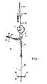
- Fig. 1 illustrates a mechanical delivery system 10 constructed using the teachings of the present invention.
- the mechanical delivery system 10 has a sensor housing 12 located at its lowermost end.
- the housing 12 carries an arm 14 which is shown in its open position in Fig. 1.
- the arm 14 has a closed position, which is shown in Fig. 2.
- the arm 14 carries a first contact-type ultrasonic sensor 16 and a second contact-type ultrasonic sensor 18.
- the sensors 16 and 18 extend laterally of the housing 12 and are capable of mating engagement with the component to be inspected.
- the arm is in its closed position, as shown in Fig. 2, the sensors 16 and 18 are within the housing 12 and are thereby protected from damage while in transit to and from the inspection site.
- the arm 14 is operated by an actuator rod 20 shown in Fig. 2, which terminates in an eye nut 21 and threaded knob 22, both illustrated in Fig. 1. Because the distance between the eye nut 21 and the housing 12 may typically be forty feet, it is desirable to protect the actuator rod 20 with extension pipes 24.
- the first extension pipe 24 mates with threads 25, shown in Fig. 2, in the upper end of the housing 12.
- the extension pipe 24 at the uppermost end of the mechanical delivery system 10 is provided with an outer support 26.
- Electrical coaxial cables 28 and 29 from the transducer 16 and electrical coaxial cables 30 and 31 from the transducer 18 are also within, and protected by, the extension piping 24.
- the coaxial cables 28, 29, 30 and 31 are capable of being connected to ultrasonic instruments such as a MARK I provided by Sonic Corp.
- the mechanical delivery system 10 is connected to a ceiling or crane hook 33 through a hoist 35, a delivery spring 37, and a scale 39.
- the eye nut 21, threaded knob 22, hoist 35, spring 37, and scale 39 are all used to precisely position the sensors 16 and 18 in a manner described hereinbelow in connection with Fig. 6.
- FIG. 2 cross-sectional views of the sensor housing 12 are shown.
- the arm 14 is shown in its closed position wherein it is parallel to and within the sensor housing 12.
- the arm 14 is connected to the sensor housing 12 by a connection pin 40 seen more clearly in Fig. 3.
- the arm 14 is responsive to two pinion gears 41 and 41' which in turn are responsive to two rack gears 43 and 43'.
- the rack gears 43 and 43' terminate in a common enlarged upper end 44 which is connected to the actuator rod 20.
- the enlarged upper end 44 of the rack gears 43 and 43' is also connected to a pin 46 which engages a guide 48.
- a biasing spring 49 is connected between the upper end of the housing 12 and the enlarged upper end 44 of the rack gears 43 and 43' with the control rod 20 running therethrough.
- the biasing spring 49 urges the rack gears 43 and 43' and the guide pin 46 back to their starting positions. That motion causes the arm 14 to swivel from the open position perpendicular to the housing 12 to its closed position as shown in Fig. 2.
- the guide pin 46 prevents stray movement of the rack gears 43 and 43' thus insuring positive engagement with pinion gears 41 and 41'.
- the second set of rack and pinion gears 43' and 41', respectively, have been added as a protective feature.
- the first transducer 16 is mounted at a right angle, or 90°, with respect to the second transducer 18. That mounting arrangement is necessary for one embodiment of the present invention which will be described in detail hereinbelow in conjunction with Fig. 6.
- first and second transducers 16 and 18, respectively are important features of the present invention and will be described in detail in conjunction with Figs. 4, 4A, and 5. It is to be understood that the following discussion of the mounting of the first transducer 16 is equally applicable to the second transducer 18.
- a cross-sectional view of the arm 14 is shown.
- the arm 14 has a cylindrical opening 57 extending therethrough and a recessed portion 59.
- the cylindrical opening 57 and recessed portion 59 are seen from another view in Fig. 4A.
- the transducer 16 is shown in detail in Fig. 5.
- An adapter 60 has an upper adapter portion 61 and a lower cylindrical adapter portion 62.
- the upper adapter portion 61 carries a transducer tongue 64 which houses an ultrasonic transmitter 81 and receiver 82.
- Two coaxial cables 28 and 29 extend from the transducer 16.
- the ultrasonic transducer may be of a type available from Ultran Laboratories, model WSP.
- the lower adapter portion 62 is cylindrical and is sized to be received by the cylindrical opening 57 in the arm 14.
- the lower cylindrical adapter portion 62 also has a slot or notch 65.
- the slot 65 is defined by a bottom surface 66, a top surface 67, and a vertical wall 68.
- a flat retaining clip 69 is attached to the arm 14 by a screw (not shown), which extends through the clip 69 into mating threads 70 in the arm 14.
- the clip 69 is designed to be received by the recessed portion 59 of the arm 14 such that the clip 69 is flush with the top surface of the arm 14.
- a portion of the clip extends into the slot 65 of the lower cylindrical adapter portion 62.
- the dimensions of the cylindrical opening 57 in the arm 14, the lower cylindrical adapter portion 62, slot 65, and clip 69 are such that the transducer 16 is permitted limited rotation (until part of the vertical wall 68 of the slot 66 meets the end surface of the clip 69) about an axis perpendicular to the arm 14.
- the sensor 16 may also be permitted limited rocking (until the lower surface 66 or the upper surface 67 of the slot 65 meet the clip 69) about a point on the axis. That limited rotation and rocking is necessary because the arm 14 may not be exactly positioned for the transducer tongue 64 to be inserted into the component to be inspected. That limited rotation and rocking is also necessary in the event that the two components to be simultaneously inspected by the transducers 16 and 18 are not in the exact position anticipated.
- the following chart summarizes the dimensions used in one embodiment to provide the sensors with the proper freedom to rotate about an axis perpendicular to the arm 14 and to rock about a point on that axis.
- a mechanical delivery system 10 using the above dimensions would typically have a housing 12 having an outside diameter of 2.25" (57.15 mm) and a distance of about 7" (17.78 cm) between the transducers 16 and 18.
- the arm 14 is constructed of a hardened material and the adapter 60 of a softer material.
- the motion of a softer adapter material on a hardened material eliminates sticking and galling.
- the overall effect of' the assembled arm 14 and transducer 16 is of a loose fit of the transducer 16 in the arm 14 but a fit which is nonetheless secure.
- the mechanical delivery system 10 positions the ultrasonic sensors 16 and 18 for inspection of split pins 72 and 74.
- the split pins 72 and 74 are used to connect a guide tube 76, which is used to guide control rods (not shown), to an upper core plate 78.
- the ultrasonic sensors 16 and 18 inspect the split pins 72 and 74 for cracks or other signs of mechanical failure.
- the mechanical delivery system 10 enables examination of the split pins 72 and 74 while they are mounted in both the guide tube 76 and the upper core plate 78; the guide tube 76 and upper core plate 78 are mounted in the upper portion of a nuclear reactor.
- the upper reactor internals (not shown) are removed from the reactor vessel and seated on an upper internals storage stand in containment.
- the ultrasonic inspection of the split pins 72 and 74 is done remotely from a manipulator bridge in containment or suitable work platform with the split pins under water approximately forty feet below.
- the mechanical delivery system 10 must deliver the transducers 16 and 18 to the split pins 72 and 74 mounted in the guide tube 76 such that the operator can remotely examine the pins to assess whether the pins are structurally sound.
- the mechanical delivery system 10 must be able to remotely engage the tongue 64 of each transducer into the slot of the split pins 72 and 74. For example, that operation may involve inserting the tongue 64 having a nominal width of .094 inches (2.388 mm) into a slot of nominal width of .126 inches (3.200 mm) from a work platform forty feet above without the aid of a camera.
- the mechanical delivery system 10 must position the transducers 16 and 18 in the split pins such that the transducers can be made to translate along the length of the split pin slot as required by the operator performing the inspection. Further, the mechanical delivery system 10 must not damage the transducers 16 and 18 in delivering the transducers to the split pins, engaging the tongues 64 with the split pin slots, and removing the transducers even though the transducers 16 and 18 are relatively fragile. Finally, the mechanical delivery system 10 must be relatively simple to operate and capable of repetitive inspections. For example, in a typical four-day examination period, 60 split pins securing 30 guide tubes will be inspected. That inspection will include inserting the mechanical delivery system 10 into a guide tube, positioning the transducers 16 and 18 into the split pins, ultrasonically examining the split pins, and removing the mechanical delivery system 10 from the guide tube.
- Fig. 6 the housing 12 has been delivered to the floor 79 at the bottom of the cavity some forty feet below a work platform.
- the eye nut 21 shown in Fig. 1 is pulled causing the swivel arm 14 to assume its open position as shown in Fig. 5.
- the threaded knob 22 is tightened to maintain the arm 14 in the open position.
- the hoist 35 shown in Fig. 1, is used to lift the entire mechanical delivery system until the tongues 64 of the transducers 16 and 18 come in contact with the bottom of the upper core plate 78. Contact can be determined by noticing an increase in the reading of the scale 39 above the mechanical delivery system's hanging weight. Once contact has been established, the mechanical delivery system is raised until a load of five pounds is placed on the tongue of each of the transducers 16 and 18. The operator then rotates the mechanical delivery system from the work platform until the transducer tongues 64 "pop" into the split pin slots. That will be accomplished when the load on the scale 39 drops to the original hanging weight of the mechanical delivery system 10. Again using the hoist 35, the mechanical delivery system is raised until the tongue 64 of each of the ultrasonic sensors 16 and 18 experiences a load of five pounds. Once that has been accomplished, the split pins are ready to be ultrasonically inspected.
- the mechanical delivery system is lowered and the threaded knob 22 is loosened allowing the bias spring 49, shown in Fig. 2, to urge the arm 14 into its closed position.
- the mechanical delivery system 10 can be removed from the guide tube 76. The process can be repeated until all of the split pins have been ultrasonically inspected.
Abstract
Description
- The present invention is related generally to remotely controllable sensors and more specifically to a mechanical delivery system for remotely positioning a contact-type ultrasonic sensor for inspecting components within a nuclear reactor.
- The use of contact-type ultrasonic sensors is well-known for the inspection of mechanical components. It is also well-known to use remotely controllable delivery systems for positioning the ultrasonic sensor when manual positioning is not possible, such as in cases of space limitations, hostile environments, etc. However, certain environments, such as inside a nuclear reactor, present unique problems.
- Typically, inspection of components within a nuclear reactor is necessary to gather data on operational performance, detect failures, comply with regulations or the like. Inspections typically occur during a scheduled outage for.refueling or routine maintenance. Such outages are kept at minimal length for economic reasons. Thus, because of the short duration of the outage, it is necessary to perform a large number of complex inspections in a very short time.
- In addition to the time constraints, the inspections must be performed from a platform far above the nuclear reactor wherein distances of thirty or even forty feet are not uncommon between the operator and the device being inspected. Further, the component to be inspected may have a notch or recess into which the ultrasonic sensor must be positioned. Thus, a specific orientation between the sensor and the component to be inspected must be achieved before the sensor can be inserted into the notch or recess. Attempts at inserting the sensor before the proper orientation is achieved may result in damage to the sensor. Damage to the sensors may also occur if the sensors collide with obstacles on the way to or from the component to be inspected.
- Considering the complexity of a nuclear reactor, the large number of inspections which must be made in a short time, and the difficulty of the "blind" positioning of a fragile sensor from a position forty feet away from the operator in a radioactive underwater environment, it is clear that the development of mechanical systems for remotely positioning the sensors presents a wide variety of challenges to the design engineer.
- The present invention in its broad form comprises a mechanical delivery and remote positioning system for remotely positioning a sensor in mating engagement with a predetermined portion of a workpiece component to be inspected, comprising: elongated support means having a first end adapted for manipulation from a remote location and a second end; a sensing means having a sensor portion adapted for mating engagement with the predetermined portion of the component to be inspected; characterized by: means for mounting said sensing means onto said support means at said second end of said support means, said mounting means permitting limited movement of said sensing means with respect to said second end to thereby enable said sensor portion to be placed in mating engagement with the predetermined portion of the workpiece component as a result of manipulation of said first end despite mispositioning of said sensor portion relative to the component.
- In accordance with a preferred embodiment of that aspect of the present invention, the sensor is carried by a cylindrical adaptor which in turn is carried by an arm which is part of the support. The adaptor is mounted to the arm such that the sensor is permitted a limited amount of rotation about an axis perpendicular to the arm and a limited amount of rocking about a point on that axis. The effect of that mounting technique is to provide the sensor with a loose fit within the arm such that the sensor can engage the component to be inspected despite mispositioning between the second end of the support and the component and at the same time positively secure the sensor to the arm.
- Expediently the arm is connected to the elongated support by a swivel means which allows movement of the arm between a first position wherein the arm is substantially completely within the support and a second expanded position wherein the portion of the arm carrying the sensor extends laterally of the support such that the sensor is positioned for mating engagement with the component's predetermined portion. Actuator means are provided for controlling movement of the arm between the first and second positions. The actuator means comprise first gear means connected to the arm, second gear means matingly engaging the first gear means, and means for moving the second gear means to cause the arm to move between the first and second positions. The means for moving is associated with the first end of the support means so that control of the position of the arm is accomplished from a remote location.
- Thus, when the arm is in the first position, within the support means, the support means may be pushed or pulled through any amount of piping or tubing without fear of damaging the sensor. When the support means reaches the location of the component to be inspected, the arm is moved into the second position such that the sensor may engage the component to be inspected.
- In the preferred embodiment described herein, an indicator is associated with the first end of the support means which provides a first indication when the sensor contacts the component to be inspected with a predetermined force and provides a second indication when the force is reduced upon the sensor's mating engagement with the predetermined portion of the component to be inspected.
- As described herein, the mechanical delivery system is positioned with the housing adjacent to the component to be inspected. The arm is deployed and the entire delivery system is moved until the sensor comes into contact with the component to be inspected. The support means is then manipulated until the sensor matingly engages the predetermined portion of the component. In a preferred embodiment, after contact with the component is made, a delivery spring is used to increase the force on the sensor. The increase in force may be shown by a scale. The delivery system is then rotated until the sensor engages the component which will be apparent from a drop in force on the sensor shown by the scale. The force on the sensor may again be increased to insure proper contact before the inspection is performed.
- . A more detailed understanding of the invention may be had from the following description of a preferred embodiment, given by way of example and to be understood in conjunction with the accompanying drawing wherein:
- Fig. 1 illustrates the mechanical delivery system of a preferred embodiment of the present invention;
- Fig. 2 is a cross-sectional view of the sensor housing of Fig. 1;
- Fig. 3 is another cross-sectional view of the sensor housing taken along the line III-III;
- Fig. 4 is detailed cross-sectional view of the arm which carries the ultrasonic transducers;
- Fig. 4A is a view of the top surface of a portion of the arm of Fig. 3;
- Fig. 5 is detailed view of an ultrasonic transducer, cylindrical adapter, and retaining clip; and
- Fig. 6 illustrates the sensor housing of the mechanical delivery system of the present invention in operation in a particular environment.
- Fig. 1 illustrates a
mechanical delivery system 10 constructed using the teachings of the present invention. Themechanical delivery system 10 has asensor housing 12 located at its lowermost end. Thehousing 12 carries anarm 14 which is shown in its open position in Fig. 1. Thearm 14 has a closed position, which is shown in Fig. 2. - The
arm 14 carries a first contact-typeultrasonic sensor 16 and a second contact-typeultrasonic sensor 18. When the arm is in its open position as shown in Fig. 1, thesensors housing 12 and are capable of mating engagement with the component to be inspected. When the arm is in its closed position, as shown in Fig. 2, thesensors housing 12 and are thereby protected from damage while in transit to and from the inspection site. - The
arm 14 is operated by an actuator rod 20 shown in Fig. 2, which terminates in aneye nut 21 and threadedknob 22, both illustrated in Fig. 1. Because the distance between theeye nut 21 and thehousing 12 may typically be forty feet, it is desirable to protect the actuator rod 20 withextension pipes 24. The first extension pipe 24 mates withthreads 25, shown in Fig. 2, in the upper end of thehousing 12. Theextension pipe 24 at the uppermost end of themechanical delivery system 10 is provided with anouter support 26. Electricalcoaxial cables transducer 16 and electricalcoaxial cables transducer 18 are also within, and protected by, theextension piping 24. Thecoaxial cables - The
mechanical delivery system 10 is connected to a ceiling orcrane hook 33 through ahoist 35, adelivery spring 37, and ascale 39. Theeye nut 21, threadedknob 22, hoist 35,spring 37, andscale 39 are all used to precisely position thesensors - Turning to Figs. 2 and 3, cross-sectional views of the
sensor housing 12 are shown. In Fig. 2, thearm 14 is shown in its closed position wherein it is parallel to and within thesensor housing 12. Thearm 14 is connected to thesensor housing 12 by aconnection pin 40 seen more clearly in Fig. 3. Thearm 14 is responsive to twopinion gears 41 and 41' which in turn are responsive to tworack gears 43 and 43'. The rack gears 43 and 43' terminate in a common enlargedupper end 44 which is connected to the actuator rod 20. The enlargedupper end 44 of the rack gears 43 and 43' is also connected to apin 46 which engages aguide 48. - A biasing
spring 49 is connected between the upper end of thehousing 12 and the enlargedupper end 44 of the rack gears 43 and 43' with the control rod 20 running therethrough. - In operation, when the control rod 20 is pulled in the direction indicated by the
arrow 50, thepin 46 and rack gears 43 and 43' move in the same direction. That movement causes the biasingspring 49 to be compressed. That movement also causes the pinion gears 41 and 41' to rotate causing thearm 14 to swivel in the directions indicated by thearrows housing 12 hasopenings housing 12, as shown in Fig. 1. - When the force on the actuator rod 20 is released, the biasing
spring 49 urges the rack gears 43 and 43' and theguide pin 46 back to their starting positions. That motion causes thearm 14 to swivel from the open position perpendicular to thehousing 12 to its closed position as shown in Fig. 2. Theguide pin 46 prevents stray movement of the rack gears 43 and 43' thus insuring positive engagement with pinion gears 41 and 41'. The second set of rack and pinion gears 43' and 41', respectively, have been added as a protective feature. - The
first transducer 16 is mounted at a right angle, or 90°, with respect to thesecond transducer 18. That mounting arrangement is necessary for one embodiment of the present invention which will be described in detail hereinbelow in conjunction with Fig. 6. - The mounting of the first and
second transducers first transducer 16 is equally applicable to thesecond transducer 18. - In Fig. 4, a cross-sectional view of the
arm 14 is shown. Thearm 14 has acylindrical opening 57 extending therethrough and a recessedportion 59. Thecylindrical opening 57 and recessedportion 59 are seen from another view in Fig. 4A. - The
transducer 16 is shown in detail in Fig. 5. Anadapter 60 has anupper adapter portion 61 and a lowercylindrical adapter portion 62. Theupper adapter portion 61 carries atransducer tongue 64 which houses anultrasonic transmitter 81 andreceiver 82. Twocoaxial cables transducer 16. The ultrasonic transducer may be of a type available from Ultran Laboratories, model WSP. - The
lower adapter portion 62 is cylindrical and is sized to be received by thecylindrical opening 57 in thearm 14. The lowercylindrical adapter portion 62 also has a slot or notch 65. Theslot 65 is defined by a bottom surface 66, atop surface 67, and avertical wall 68. - When the lower
cylindrical adapter portion 62 is inserted in thecylindrical opening 57, aflat retaining clip 69 is attached to thearm 14 by a screw (not shown), which extends through theclip 69 intomating threads 70 in thearm 14. Theclip 69 is designed to be received by the recessedportion 59 of thearm 14 such that theclip 69 is flush with the top surface of thearm 14. When the retainingclip 69 is attached, a portion of the clip extends into theslot 65 of the lowercylindrical adapter portion 62. The dimensions of thecylindrical opening 57 in thearm 14, the lowercylindrical adapter portion 62,slot 65, andclip 69 are such that thetransducer 16 is permitted limited rotation (until part of thevertical wall 68 of the slot 66 meets the end surface of the clip 69) about an axis perpendicular to thearm 14. Thesensor 16 may also be permitted limited rocking (until the lower surface 66 or theupper surface 67 of theslot 65 meet the clip 69) about a point on the axis. That limited rotation and rocking is necessary because thearm 14 may not be exactly positioned for thetransducer tongue 64 to be inserted into the component to be inspected. That limited rotation and rocking is also necessary in the event that the two components to be simultaneously inspected by thetransducers - The following chart summarizes the dimensions used in one embodiment to provide the sensors with the proper freedom to rotate about an axis perpendicular to the
arm 14 and to rock about a point on that axis.
- A
mechanical delivery system 10 using the above dimensions would typically have ahousing 12 having an outside diameter of 2.25" (57.15 mm) and a distance of about 7" (17.78 cm) between thetransducers - In addition to the attention that must be paid to the dimensions of the
arm 14, lowercylindrical adapter portion 62, and theclip 69, thearm 14 is constructed of a hardened material and theadapter 60 of a softer material. Thus, the motion of a softer adapter material on a hardened material eliminates sticking and galling. The overall effect of' the assembledarm 14 andtransducer 16 is of a loose fit of thetransducer 16 in thearm 14 but a fit which is nonetheless secure. - The operation of the
mechanical delivery system 10 shown in Fig. 1 will now be described in a particular environment in conjunction with Fig. 6. In Fig. 6, themechanical delivery system 10 positions theultrasonic sensors split pins guide tube 76, which is used to guide control rods (not shown), to anupper core plate 78. Theultrasonic sensors split pins mechanical delivery system 10 enables examination of thesplit pins guide tube 76 and theupper core plate 78; theguide tube 76 andupper core plate 78 are mounted in the upper portion of a nuclear reactor. For ultrasonic examination, the upper reactor internals (not shown) are removed from the reactor vessel and seated on an upper internals storage stand in containment. The ultrasonic inspection of thesplit pins - In that environment, the
mechanical delivery system 10 must deliver thetransducers split pins guide tube 76 such that the operator can remotely examine the pins to assess whether the pins are structurally sound. Themechanical delivery system 10 must be able to remotely engage thetongue 64 of each transducer into the slot of thesplit pins tongue 64 having a nominal width of .094 inches (2.388 mm) into a slot of nominal width of .126 inches (3.200 mm) from a work platform forty feet above without the aid of a camera. Themechanical delivery system 10 must position thetransducers mechanical delivery system 10 must not damage thetransducers tongues 64 with the split pin slots, and removing the transducers even though thetransducers mechanical delivery system 10 must be relatively simple to operate and capable of repetitive inspections. For example, in a typical four-day examination period, 60 split pins securing 30 guide tubes will be inspected. That inspection will include inserting themechanical delivery system 10 into a guide tube, positioning thetransducers mechanical delivery system 10 from the guide tube. - In Fig. 6, the
housing 12 has been delivered to thefloor 79 at the bottom of the cavity some forty feet below a work platform. When the bottom is reached, theeye nut 21 shown in Fig. 1, is pulled causing theswivel arm 14 to assume its open position as shown in Fig. 5. When thearm 14 has been fully opened, the threadedknob 22 is tightened to maintain thearm 14 in the open position. - The hoist 35, shown in Fig. 1, is used to lift the entire mechanical delivery system until the
tongues 64 of thetransducers upper core plate 78. Contact can be determined by noticing an increase in the reading of thescale 39 above the mechanical delivery system's hanging weight. Once contact has been established, the mechanical delivery system is raised until a load of five pounds is placed on the tongue of each of thetransducers transducer tongues 64 "pop" into the split pin slots. That will be accomplished when the load on thescale 39 drops to the original hanging weight of themechanical delivery system 10. Again using the hoist 35, the mechanical delivery system is raised until thetongue 64 of each of theultrasonic sensors - After inspection, the mechanical delivery system is lowered and the threaded
knob 22 is loosened allowing thebias spring 49, shown in Fig. 2, to urge thearm 14 into its closed position. Once thearm 14 is in its closed position, themechanical delivery system 10 can be removed from theguide tube 76. The process can be repeated until all of the split pins have been ultrasonically inspected. - The description of the present invention in conjunction with an environment wherein two split pins are ultrasonically inspected is intended merely as an example and not a limitation. It is anticipated that the principles of the present invention may be modified to suit a variety of environments. Such modifications may be made without departing from the scope and content of the present invention as defined by the following claims.
Claims (18)
Applications Claiming Priority (2)
| Application Number | Priority Date | Filing Date | Title |
|---|---|---|---|
| US670421 | 1984-11-09 | ||
| US06/670,421 US4689994A (en) | 1984-11-09 | 1984-11-09 | Delivery system for a remote sensor |
Publications (3)
| Publication Number | Publication Date |
|---|---|
| EP0180896A2 true EP0180896A2 (en) | 1986-05-14 |
| EP0180896A3 EP0180896A3 (en) | 1986-12-30 |
| EP0180896B1 EP0180896B1 (en) | 1990-02-28 |
Family
ID=24690331
Family Applications (1)
| Application Number | Title | Priority Date | Filing Date |
|---|---|---|---|
| EP85113715A Expired - Lifetime EP0180896B1 (en) | 1984-11-09 | 1985-10-29 | Delivery system for a remote sensor |
Country Status (6)
| Country | Link |
|---|---|
| US (1) | US4689994A (en) |
| EP (1) | EP0180896B1 (en) |
| JP (2) | JPS61118657A (en) |
| KR (1) | KR930011019B1 (en) |
| DE (1) | DE3576238D1 (en) |
| ES (1) | ES8704028A1 (en) |
Families Citing this family (6)
| Publication number | Priority date | Publication date | Assignee | Title |
|---|---|---|---|---|
| US4818470A (en) * | 1987-08-31 | 1989-04-04 | General Electric Company | Apparatus for the ultrasonic examination of shroud hold down bolts |
| JP2619020B2 (en) * | 1988-10-27 | 1997-06-11 | 株式会社東芝 | Reactor pressure vessel inspection equipment |
| US5078955A (en) * | 1989-06-14 | 1992-01-07 | Westinghouse Electric Corp. | Control rod guide tube inspection system |
| US6639959B1 (en) * | 2002-05-06 | 2003-10-28 | General Electric Company | Guide tube camera inspection fixture and method of use |
| US7246790B1 (en) * | 2006-05-05 | 2007-07-24 | Ulric Francoeur | Hoist System |
| US20130058448A1 (en) * | 2011-09-06 | 2013-03-07 | Battelle Energy Alliance, Llc | Vibro-acoustic sensors for materials characterization and related methods and systems |
Citations (4)
| Publication number | Priority date | Publication date | Assignee | Title |
|---|---|---|---|---|
| DE2153397B2 (en) * | 1971-10-27 | 1974-04-18 | Maschinenfabrik Augsburg-Nuernberg Ag, 8900 Augsburg | |
| DE2902105A1 (en) * | 1978-01-20 | 1979-07-26 | Roentgen Tech Dienst Bv | DEVICE FOR EXAMINING WELD SEAMS |
| JPS5753657A (en) * | 1980-09-18 | 1982-03-30 | Toshiba Corp | Ultrasonic flaw detector |
| EP0098188A1 (en) * | 1982-06-14 | 1984-01-11 | Commissariat à l'Energie Atomique | Device for the remote determination of spring characteristics |
Family Cites Families (10)
| Publication number | Priority date | Publication date | Assignee | Title |
|---|---|---|---|---|
| US3508439A (en) * | 1966-12-09 | 1970-04-28 | Schlumberger Technology Corp | Combination sidewall neutron porosity and sonic tool |
| FR2168920B1 (en) * | 1972-01-26 | 1975-06-13 | Schlumberger Prospection | |
| FR2242750B1 (en) * | 1973-08-27 | 1976-12-03 | Commissariat Energie Atomique | |
| DE2557992C3 (en) * | 1975-12-22 | 1978-06-29 | Kraftwerk Union Ag, 4330 Muelheim | Test system carrier for testing the connection nozzle area in pressure vessels, especially reactor pressure vessels of nuclear power plants with ultrasound |
| US4302286A (en) * | 1979-04-24 | 1981-11-24 | Westinghouse Electric Corp. | Reactor vessel in-service inspection assembly and ultrasonic centering device |
| US4394345A (en) * | 1980-12-29 | 1983-07-19 | General Electric Company | Ultrasonic method and apparatus |
| JPS57148248A (en) * | 1981-03-10 | 1982-09-13 | Hitachi Ltd | Ultrasonic defect finding device |
| JPS5824787U (en) * | 1981-08-08 | 1983-02-16 | 新明和工業株式会社 | tank truck tank |
| US4432271A (en) * | 1981-08-17 | 1984-02-21 | Combustion Engineering, Inc. | Locomotion unit for a tool support adapted for progression through passageways |
| US4597294A (en) * | 1984-06-25 | 1986-07-01 | Westinghouse Electric Corp. | Ultrasonic nondestructive tubing inspection system |
-
1984
- 1984-11-09 US US06/670,421 patent/US4689994A/en not_active Expired - Lifetime
-
1985
- 1985-10-29 DE DE8585113715T patent/DE3576238D1/en not_active Expired - Fee Related
- 1985-10-29 EP EP85113715A patent/EP0180896B1/en not_active Expired - Lifetime
- 1985-11-07 ES ES548673A patent/ES8704028A1/en not_active Expired
- 1985-11-08 KR KR1019850008358A patent/KR930011019B1/en not_active IP Right Cessation
- 1985-11-08 JP JP60249143A patent/JPS61118657A/en active Pending
-
1994
- 1994-11-07 JP JP1994013670U patent/JP2500354Y2/en not_active Expired - Lifetime
Patent Citations (4)
| Publication number | Priority date | Publication date | Assignee | Title |
|---|---|---|---|---|
| DE2153397B2 (en) * | 1971-10-27 | 1974-04-18 | Maschinenfabrik Augsburg-Nuernberg Ag, 8900 Augsburg | |
| DE2902105A1 (en) * | 1978-01-20 | 1979-07-26 | Roentgen Tech Dienst Bv | DEVICE FOR EXAMINING WELD SEAMS |
| JPS5753657A (en) * | 1980-09-18 | 1982-03-30 | Toshiba Corp | Ultrasonic flaw detector |
| EP0098188A1 (en) * | 1982-06-14 | 1984-01-11 | Commissariat à l'Energie Atomique | Device for the remote determination of spring characteristics |
Non-Patent Citations (1)
| Title |
|---|
| PATENT ABSTRACTS OF JAPAN, vol. 6, no. 129 (P-128)[1007], 15th July 1982; & JP - A - 57 53657 (TOKYO SHIBAURA) 30-03-1982 * |
Also Published As
| Publication number | Publication date |
|---|---|
| JPS61118657A (en) | 1986-06-05 |
| KR930011019B1 (en) | 1993-11-19 |
| EP0180896A3 (en) | 1986-12-30 |
| EP0180896B1 (en) | 1990-02-28 |
| ES548673A0 (en) | 1987-03-01 |
| DE3576238D1 (en) | 1990-04-05 |
| ES8704028A1 (en) | 1987-03-01 |
| US4689994A (en) | 1987-09-01 |
| JP2500354Y2 (en) | 1996-06-05 |
| JPH0738961U (en) | 1995-07-14 |
| KR860004426A (en) | 1986-06-23 |
Similar Documents
| Publication | Publication Date | Title |
|---|---|---|
| EP0180896A2 (en) | Delivery system for a remote sensor | |
| US4491018A (en) | Pig detector | |
| US5756908A (en) | Probe positioner | |
| USH1262H (en) | Rod examination gauge | |
| CN202486104U (en) | System for detecting fir tree type blade roots of turbine | |
| TW303422B (en) | ||
| JPS6367514A (en) | External size related measuring device for nuclear fuel aggregate | |
| TW314630B (en) | ||
| EP3146525B1 (en) | Transportable monitoring system | |
| EP0625266A4 (en) | Method and apparatus for ultrasonic inspection of inaccessible areas. | |
| US4903281A (en) | System for fuel rod removal from a reactor module | |
| JP2019515301A (en) | Probe crash detection mechanism and method of clinical analyzer | |
| KR940007203B1 (en) | Device for the remote feeding of cylindrical pieles to an automatic machine such as a machine plugging the tubes of a steam generator of a pressurized-water nuclear reactor | |
| JPH07306291A (en) | Measuring equipment | |
| NO20140935A1 (en) | Apparatus and method for monitoring the structural integrity of a pipeline | |
| JP2001099817A (en) | Ultrasonic flaw-detecting device | |
| RU2807667C1 (en) | Method for handling spent control and protection rods of shipboard nuclear power plants using a complex for handling spent control and protection rods | |
| CN220063117U (en) | Coal level detection device based on pressure sensing | |
| Matchett et al. | System for fuel rod removal from a reactor module | |
| McNair | Robotic real-time radiographic inspection system | |
| Heine et al. | An experimental nodule collection vehicle design and testing | |
| JP3061888B2 (en) | Fuel assembly inspection device | |
| JP3281178B2 (en) | Dimension and shape measuring device for control rod drive mechanism housing | |
| Bacvinskas et al. | Rod examination gauge | |
| Carey | The Design and Commissioning of a Non Destructive Examination (NDE) Facility for the In-Pool Testing of Light Water Reactor (LWR) Fuel Rods |
Legal Events
| Date | Code | Title | Description |
|---|---|---|---|
| PUAI | Public reference made under article 153(3) epc to a published international application that has entered the european phase |
Free format text: ORIGINAL CODE: 0009012 |
|
| AK | Designated contracting states |
Kind code of ref document: A2 Designated state(s): BE CH DE FR GB IT LI SE |
|
| PUAL | Search report despatched |
Free format text: ORIGINAL CODE: 0009013 |
|
| AK | Designated contracting states |
Kind code of ref document: A3 Designated state(s): BE CH DE FR GB IT LI SE |
|
| 17P | Request for examination filed |
Effective date: 19870603 |
|
| 17Q | First examination report despatched |
Effective date: 19890126 |
|
| ITF | It: translation for a ep patent filed |
Owner name: ING. ZINI MARANESI & C. S.R.L. |
|
| GRAA | (expected) grant |
Free format text: ORIGINAL CODE: 0009210 |
|
| AK | Designated contracting states |
Kind code of ref document: B1 Designated state(s): BE CH DE FR GB IT LI SE |
|
| ET | Fr: translation filed | ||
| REF | Corresponds to: |
Ref document number: 3576238 Country of ref document: DE Date of ref document: 19900405 |
|
| PLBE | No opposition filed within time limit |
Free format text: ORIGINAL CODE: 0009261 |
|
| STAA | Information on the status of an ep patent application or granted ep patent |
Free format text: STATUS: NO OPPOSITION FILED WITHIN TIME LIMIT |
|
| 26N | No opposition filed | ||
| ITTA | It: last paid annual fee | ||
| EAL | Se: european patent in force in sweden |
Ref document number: 85113715.8 |
|
| PGFP | Annual fee paid to national office [announced via postgrant information from national office to epo] |
Ref country code: GB Payment date: 20000918 Year of fee payment: 16 |
|
| PGFP | Annual fee paid to national office [announced via postgrant information from national office to epo] |
Ref country code: SE Payment date: 20001004 Year of fee payment: 16 |
|
| PGFP | Annual fee paid to national office [announced via postgrant information from national office to epo] |
Ref country code: FR Payment date: 20001009 Year of fee payment: 16 |
|
| PGFP | Annual fee paid to national office [announced via postgrant information from national office to epo] |
Ref country code: DE Payment date: 20001030 Year of fee payment: 16 |
|
| PGFP | Annual fee paid to national office [announced via postgrant information from national office to epo] |
Ref country code: BE Payment date: 20001120 Year of fee payment: 16 |
|
| PGFP | Annual fee paid to national office [announced via postgrant information from national office to epo] |
Ref country code: CH Payment date: 20010103 Year of fee payment: 16 |
|
| PG25 | Lapsed in a contracting state [announced via postgrant information from national office to epo] |
Ref country code: GB Free format text: LAPSE BECAUSE OF NON-PAYMENT OF DUE FEES Effective date: 20011029 |
|
| PG25 | Lapsed in a contracting state [announced via postgrant information from national office to epo] |
Ref country code: SE Free format text: LAPSE BECAUSE OF NON-PAYMENT OF DUE FEES Effective date: 20011030 |
|
| PG25 | Lapsed in a contracting state [announced via postgrant information from national office to epo] |
Ref country code: LI Free format text: LAPSE BECAUSE OF NON-PAYMENT OF DUE FEES Effective date: 20011031 Ref country code: CH Free format text: LAPSE BECAUSE OF NON-PAYMENT OF DUE FEES Effective date: 20011031 Ref country code: BE Free format text: LAPSE BECAUSE OF NON-PAYMENT OF DUE FEES Effective date: 20011031 |
|
| REG | Reference to a national code |
Ref country code: GB Ref legal event code: IF02 |
|
| BERE | Be: lapsed |
Owner name: WESTINHOUSE ELECTRIC CY LLC Effective date: 20011031 |
|
| EUG | Se: european patent has lapsed |
Ref document number: 85113715.8 |
|
| REG | Reference to a national code |
Ref country code: CH Ref legal event code: PL |
|
| GBPC | Gb: european patent ceased through non-payment of renewal fee |
Effective date: 20011029 |
|
| PG25 | Lapsed in a contracting state [announced via postgrant information from national office to epo] |
Ref country code: FR Free format text: LAPSE BECAUSE OF NON-PAYMENT OF DUE FEES Effective date: 20020628 |
|
| PG25 | Lapsed in a contracting state [announced via postgrant information from national office to epo] |
Ref country code: DE Free format text: LAPSE BECAUSE OF NON-PAYMENT OF DUE FEES Effective date: 20020702 |
|
| REG | Reference to a national code |
Ref country code: FR Ref legal event code: ST |