EP0180481A2 - Thermoelementvakuummeter - Google Patents
Thermoelementvakuummeter Download PDFInfo
- Publication number
- EP0180481A2 EP0180481A2 EP85307926A EP85307926A EP0180481A2 EP 0180481 A2 EP0180481 A2 EP 0180481A2 EP 85307926 A EP85307926 A EP 85307926A EP 85307926 A EP85307926 A EP 85307926A EP 0180481 A2 EP0180481 A2 EP 0180481A2
- Authority
- EP
- European Patent Office
- Prior art keywords
- thermocouple
- pressure
- signal
- proportional
- partial vacuum
- Prior art date
- Legal status (The legal status is an assumption and is not a legal conclusion. Google has not performed a legal analysis and makes no representation as to the accuracy of the status listed.)
- Granted
Links
- 238000010438 heat treatment Methods 0.000 claims abstract description 17
- 230000007423 decrease Effects 0.000 claims description 6
- 238000000034 method Methods 0.000 claims description 3
- 238000010586 diagram Methods 0.000 description 18
- 230000000694 effects Effects 0.000 description 5
- 238000001816 cooling Methods 0.000 description 4
- 239000007789 gas Substances 0.000 description 4
- 230000035945 sensitivity Effects 0.000 description 3
- 230000009471 action Effects 0.000 description 2
- 230000008901 benefit Effects 0.000 description 2
- 238000005259 measurement Methods 0.000 description 2
- 230000007246 mechanism Effects 0.000 description 2
- 230000003247 decreasing effect Effects 0.000 description 1
- 238000009792 diffusion process Methods 0.000 description 1
- 230000005670 electromagnetic radiation Effects 0.000 description 1
- 230000007613 environmental effect Effects 0.000 description 1
- 238000004880 explosion Methods 0.000 description 1
- 238000010348 incorporation Methods 0.000 description 1
- 230000009467 reduction Effects 0.000 description 1
Images

Classifications
-
- G—PHYSICS
- G01—MEASURING; TESTING
- G01L—MEASURING FORCE, STRESS, TORQUE, WORK, MECHANICAL POWER, MECHANICAL EFFICIENCY, OR FLUID PRESSURE
- G01L21/00—Vacuum gauges
- G01L21/10—Vacuum gauges by measuring variations in the heat conductivity of the medium, the pressure of which is to be measured
- G01L21/14—Vacuum gauges by measuring variations in the heat conductivity of the medium, the pressure of which is to be measured using thermocouples
Definitions
- thermocouple apparatus to measure low pressures under partial vacuum, more particulaly to an apparatus sensitive to pressures over a wider range.
- thermocouples have long been used as a pressure sensing device for partial vacuums.
- the thermocouple is heated and the resulting temperature of the thermocouple is measured using the thermocouple EMF.
- the rate of cooling of the thermocouple by the gas decreases.
- either the temperature of the thermocouple for constant heating current rises or the current needed to keep the thermocouple at constant temperature decreases.
- thermocouple pressure gauges of the prior art are limited in their range and sensitivity by the noise generated by simultaneous heating during measurement.
- Prior art thermocouple gauges are insensitive at low pressures and in the range of pressures 10-100 Torr.
- the object of the invention is to provide an inexpensive, modestly accurate, fast responding vacuum indicator using the thermocouple effect over many orders of magnitude of pressure.
- a time-multiplexed servomechanism is used to supply a duration modulated constant amplitude heating pulse to the thermocouple.
- the EMF of the thermocouple is measured and compared to the reference voltage.
- the reference voltage is different for different ranges of pressure and in some ranges it becomes proportional to decreases in pressure.
- the duty cycle of the heating pulses is converted to voltage and displayed as pressure.
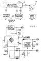
- FIG. 1 a block diagram of the thermocouple pressure gauge according to the invention.
- a time-multiplexed servomechanism 10 is used to supply a frequency modulated constant amplitude current "L" to a two wire or four wire thermocouple 12.
- the thermally generated EMF, "L” is measured, and compared to a reference voltage level “R” derived by a reference generator 14.
- the current needed to heat the junction is signalled with voltages "N” and “J” to a duty cycle generator 14.
- the duty cycle generator 16 derives a signal “H” which is proportional to the pressure and is used for control or display and with a reference voltage “B” from the power supply is input to the reference generator 16 which generates the reference signal "R".
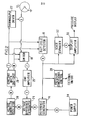
- FIG. 2 A more detailed example of the preferred embodiment of the invention is shown in FIG. 2.
- a central part of the time-multiplexed servomechanism is the switch 18 which time-multiplexes the EMF signal from the thermocouple.
- the signal “J” is sent to the switch 18 to disconnect the EMF signal "Z” to the EMF amplifier 20 and simultaneously to the thermocouple driver 22 to heat the thermocouple.
- the signal “D” extends the time in which "Z” is disconnected by the switch 18 by a small amount of time to allow the current from the thermocouple driver 22 to decay to zero current.
- the amplified EMF signals "Y” is sent from the amplifier 20 to the voltage difference integrator 24 which integrates the signals "R-Y" to generate the signal "W”.
- the signal “W” is used in turn to control the voltage controlled oscillator 26.
- the pulse frequency signal “M” from the voltage controlled oscillator 23 is sent to the constant width one-shot 28 which in turn generates the signals "J" and "N".
- the signal "H” which is proportional to the pressure can be sent to a pressure conditional control 28 which can be used to open or close valves, turn-on or turn-off pumps or take other appropriate action when the pressure crosses a preset level. Either polarity of action may take place when pressure either exceeds or falls below the preset level. A multiplicity of set points is also allowable.
- the pressure signal “H” can also be sent to a display amplifier 30.
- a scale expander 32 amplifies the signal “H” when small and saturates at large signals deriving thereby the signal "G" which is sent to the display amplifer 30.
- a conventional power supply 34 is used to supply appropriate voltages to other circuits.
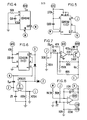
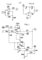
- FIGS. 3 through 14 Detailed diagrams of each of these circuits are shown in FIGS. 3 through 14. All operational amplifiers are RCA CA3260. All unlabelled diodes are small signal diodes, typically 1N914.
- thermocouple wire and electromagnetic radiation are significant compared to the loss of heat by gaseous diffusion, which is the mechanism sensitive to pressure.
- the effect of temperature on conductive cooling is eliminated and its effect on radiative loss is reduced. If temperature is constant with pressure, the effect of gaseous cooling is maximized.
- the regions where such high sensitivity is desirable are below 10 milliTorr and between 10 and 200 Torr.
- regions where the thermocouple gauge is inherently sensitive to gaseous cooling it is desirable to decrease the sensitity by decreasing the temperature with increasing pressure. These regions are between 10 milliTorr and 10 Torr and between 200 Torr and atmospheric pressure.
- a schematic diagram of temperature versus pressure for these regions is shown in FIG. 15. Manipulating the temperature as hereinbefore described allows effective measurement of pressure and enhances scale linearity over a wider range than heretofore possible, approximately six orders of magnitude.
- thermocouple thermocouple
- junction temperature much lower, safer values at pressures where such a hazard may exist in certain gases.
- the time-multiplexed heating of the junction provides two major advantages: ( i) During the interval that the thermal EMF is measured, there are no extraneous contributions to the measured voltage from the heating mechanism. Such errors are inherent in any other technique which uses DC power. (ii) Only a two wire junction is required, where previously a four wire junction was necessary. This results in several benefits, including a two wire cable from controller to gauge, a simplified gauge, and a 50 percent reduction in unwanted thermal conduction since the number of thermal conduction paths have been halved.
Landscapes
- Physics & Mathematics (AREA)
- General Physics & Mathematics (AREA)
- Measuring Fluid Pressure (AREA)
Applications Claiming Priority (2)
| Application Number | Priority Date | Filing Date | Title |
|---|---|---|---|
| US667021 | 1984-10-31 | ||
| US06/667,021 US4579002A (en) | 1984-10-31 | 1984-10-31 | Thermocouple vacuum gauge |
Publications (3)
| Publication Number | Publication Date |
|---|---|
| EP0180481A2 true EP0180481A2 (de) | 1986-05-07 |
| EP0180481A3 EP0180481A3 (en) | 1989-02-01 |
| EP0180481B1 EP0180481B1 (de) | 1991-01-30 |
Family
ID=24676479
Family Applications (1)
| Application Number | Title | Priority Date | Filing Date |
|---|---|---|---|
| EP85307926A Expired EP0180481B1 (de) | 1984-10-31 | 1985-10-31 | Thermoelementvakuummeter |
Country Status (6)
| Country | Link |
|---|---|
| US (1) | US4579002A (de) |
| EP (1) | EP0180481B1 (de) |
| JP (1) | JPH0650273B2 (de) |
| CA (1) | CA1255115A (de) |
| DE (1) | DE3581586D1 (de) |
| IL (1) | IL76666A (de) |
Families Citing this family (12)
| Publication number | Priority date | Publication date | Assignee | Title |
|---|---|---|---|---|
| US4579002A (en) | 1984-10-31 | 1986-04-01 | Varian Associates, Inc. | Thermocouple vacuum gauge |
| US4633717A (en) * | 1985-07-31 | 1987-01-06 | Varian Associates, Inc. | Thermocouple vacuum gauge |
| US5351551A (en) * | 1993-05-27 | 1994-10-04 | The Fredericks Company | Convection thermocouple vacuum gauge |
| KR20040013341A (ko) * | 2002-08-06 | 2004-02-14 | (주) 포스백 | 시간분할형 펠티어 진공게이지 구동회로 |
| US20060021444A1 (en) * | 2004-07-28 | 2006-02-02 | Helix Technology Corporation | Method of operating a resistive heat-loss pressure sensor |
| US7249516B2 (en) * | 2004-07-28 | 2007-07-31 | Brooks Automation, Inc. | Method of operating a resistive heat-loss pressure sensor |
| US7585166B2 (en) * | 2005-05-02 | 2009-09-08 | Buja Frederick J | System for monitoring temperature and pressure during a molding process |
| US7451652B2 (en) * | 2005-12-28 | 2008-11-18 | Sumitomo Heavy Industries, Ltd. | Interrupted DC operation of thermocouple vacuum gauge |
| US8790256B2 (en) | 2006-08-14 | 2014-07-29 | Frederick J. Buja | System and method employing a thermocouple junction for monitoring of physiological parameters |
| US8047711B2 (en) * | 2008-08-06 | 2011-11-01 | Heinz Ploechinger | Thermocouple vacuum gauge |
| US8986205B2 (en) | 2010-05-14 | 2015-03-24 | Frederick J. Buja | Sensor for measurement of temperature and pressure for a cyclic process |
| US10222285B2 (en) | 2014-10-24 | 2019-03-05 | Timothy G. Collins | Portable graphing vacuum pressure gauge |
Family Cites Families (5)
| Publication number | Priority date | Publication date | Assignee | Title |
|---|---|---|---|---|
| US3021712A (en) * | 1958-02-25 | 1962-02-20 | New York Air Brake Co | Pressure gauge |
| US3066537A (en) * | 1958-07-24 | 1962-12-04 | New York Air Brake Co | Pressure gauge |
| US3397579A (en) * | 1966-01-27 | 1968-08-20 | Nat Res Corp | Thermocouple gauge control |
| FR2193487A5 (de) * | 1972-07-21 | 1974-02-15 | Onera (Off Nat Aerospatiale) | |
| US4579002A (en) | 1984-10-31 | 1986-04-01 | Varian Associates, Inc. | Thermocouple vacuum gauge |
-
1984
- 1984-10-31 US US06/667,021 patent/US4579002A/en not_active Expired - Lifetime
-
1985
- 1985-10-11 IL IL76666A patent/IL76666A/xx not_active IP Right Cessation
- 1985-10-14 JP JP60227067A patent/JPH0650273B2/ja not_active Expired - Fee Related
- 1985-10-24 CA CA000493717A patent/CA1255115A/en not_active Expired
- 1985-10-31 DE DE8585307926T patent/DE3581586D1/de not_active Expired - Lifetime
- 1985-10-31 EP EP85307926A patent/EP0180481B1/de not_active Expired
Also Published As
| Publication number | Publication date |
|---|---|
| CA1255115A (en) | 1989-06-06 |
| DE3581586D1 (de) | 1991-03-07 |
| EP0180481A3 (en) | 1989-02-01 |
| IL76666A (en) | 1989-07-31 |
| JPH0650273B2 (ja) | 1994-06-29 |
| EP0180481B1 (de) | 1991-01-30 |
| IL76666A0 (en) | 1986-02-28 |
| US4579002A (en) | 1986-04-01 |
| JPS61108940A (ja) | 1986-05-27 |
Similar Documents
| Publication | Publication Date | Title |
|---|---|---|
| US4579002A (en) | Thermocouple vacuum gauge | |
| CA1048622A (en) | Transistor pair temperature sensor | |
| US5281026A (en) | Printed circuit board with cooling monitoring system | |
| EP0218318B1 (de) | Lagesensor für magnetisch aufgehängtes Teil | |
| US5475623A (en) | Method for the conversion of a measured signal, a converter as well as a measurement setup and a pirani measuring circuit | |
| GB1210432A (en) | Improvements in and relating to electronic circuits for temperature control | |
| US4633717A (en) | Thermocouple vacuum gauge | |
| US4888987A (en) | High sensitivity measurement device for measuring various parameters of non-electric quantity | |
| US3657630A (en) | Electro servosystem for a force balancing gauge | |
| SU884587A3 (ru) | Устройство дл измерени плотности газообразных сред | |
| GB1516396A (en) | Measuring the rms value of alternating current signals | |
| US3501694A (en) | Ohmmeter circuit having stabilizing circuit which reduces the effect of source variations on indication | |
| US3602830A (en) | A constant current control circuit | |
| US2977499A (en) | Electronic drift compensator | |
| RU2059251C1 (ru) | Струйный датчик угловой скорости | |
| CA2066950A1 (en) | Continuously operated gas analyser | |
| US3478203A (en) | Linear scan readout for quantities which vary in proportion to the second or higher powers of applied scan field and mass spectrometers using same | |
| US2759089A (en) | Temperature control circuit | |
| SU813464A1 (ru) | Квадратор | |
| SU985809A1 (ru) | Устройство дл передачи и приема сигналов | |
| SU805218A1 (ru) | Способ поверки электротепловых им-пульСНыХ дАТчиКОВ НЕэлЕКТРичЕСКиХВЕличиН | |
| SE8401025D0 (sv) | Anordning for beroringsfri temperaturmetning | |
| JPS6441825A (en) | Temperature measuring system | |
| SU1490590A1 (ru) | Устройство дл непрерывного контрол износа металлических пар трени | |
| US2566314A (en) | Temperature indicating apparatus |
Legal Events
| Date | Code | Title | Description |
|---|---|---|---|
| PUAI | Public reference made under article 153(3) epc to a published international application that has entered the european phase |
Free format text: ORIGINAL CODE: 0009012 |
|
| AK | Designated contracting states |
Kind code of ref document: A2 Designated state(s): CH DE FR GB IT LI |
|
| 17P | Request for examination filed |
Effective date: 19860528 |
|
| PUAL | Search report despatched |
Free format text: ORIGINAL CODE: 0009013 |
|
| AK | Designated contracting states |
Kind code of ref document: A3 Designated state(s): CH DE FR GB IT LI |
|
| 17Q | First examination report despatched |
Effective date: 19900319 |
|
| GRAA | (expected) grant |
Free format text: ORIGINAL CODE: 0009210 |
|
| AK | Designated contracting states |
Kind code of ref document: B1 Designated state(s): CH DE FR GB IT LI |
|
| REF | Corresponds to: |
Ref document number: 3581586 Country of ref document: DE Date of ref document: 19910307 |
|
| ET | Fr: translation filed | ||
| ITF | It: translation for a ep patent filed | ||
| PLBE | No opposition filed within time limit |
Free format text: ORIGINAL CODE: 0009261 |
|
| STAA | Information on the status of an ep patent application or granted ep patent |
Free format text: STATUS: NO OPPOSITION FILED WITHIN TIME LIMIT |
|
| 26N | No opposition filed | ||
| REG | Reference to a national code |
Ref country code: FR Ref legal event code: TP |
|
| REG | Reference to a national code |
Ref country code: GB Ref legal event code: 732E |
|
| PGFP | Annual fee paid to national office [announced via postgrant information from national office to epo] |
Ref country code: FR Payment date: 20011002 Year of fee payment: 17 |
|
| PGFP | Annual fee paid to national office [announced via postgrant information from national office to epo] |
Ref country code: GB Payment date: 20011004 Year of fee payment: 17 Ref country code: DE Payment date: 20011004 Year of fee payment: 17 Ref country code: CH Payment date: 20011004 Year of fee payment: 17 |
|
| REG | Reference to a national code |
Ref country code: GB Ref legal event code: IF02 |
|
| PG25 | Lapsed in a contracting state [announced via postgrant information from national office to epo] |
Ref country code: LI Free format text: LAPSE BECAUSE OF NON-PAYMENT OF DUE FEES Effective date: 20021031 Ref country code: GB Free format text: LAPSE BECAUSE OF NON-PAYMENT OF DUE FEES Effective date: 20021031 Ref country code: CH Free format text: LAPSE BECAUSE OF NON-PAYMENT OF DUE FEES Effective date: 20021031 |
|
| PG25 | Lapsed in a contracting state [announced via postgrant information from national office to epo] |
Ref country code: DE Free format text: LAPSE BECAUSE OF NON-PAYMENT OF DUE FEES Effective date: 20030501 |
|
| REG | Reference to a national code |
Ref country code: CH Ref legal event code: PL |
|
| GBPC | Gb: european patent ceased through non-payment of renewal fee | ||
| PG25 | Lapsed in a contracting state [announced via postgrant information from national office to epo] |
Ref country code: FR Free format text: LAPSE BECAUSE OF NON-PAYMENT OF DUE FEES Effective date: 20030630 |
|
| REG | Reference to a national code |
Ref country code: FR Ref legal event code: ST |