EP0179722B1 - Joint d'étanchéité pneumatique de sécurité en élastomère à cloison intérieure - Google Patents
Joint d'étanchéité pneumatique de sécurité en élastomère à cloison intérieure Download PDFInfo
- Publication number
- EP0179722B1 EP0179722B1 EP85420155A EP85420155A EP0179722B1 EP 0179722 B1 EP0179722 B1 EP 0179722B1 EP 85420155 A EP85420155 A EP 85420155A EP 85420155 A EP85420155 A EP 85420155A EP 0179722 B1 EP0179722 B1 EP 0179722B1
- Authority
- EP
- European Patent Office
- Prior art keywords
- internal
- partition
- sealing
- width
- side walls
- Prior art date
- Legal status (The legal status is an assumption and is not a legal conclusion. Google has not performed a legal analysis and makes no representation as to the accuracy of the status listed.)
- Expired
Links
- 238000005192 partition Methods 0.000 title claims description 44
- 239000013536 elastomeric material Substances 0.000 title 1
- 238000012856 packing Methods 0.000 title 1
- 238000007789 sealing Methods 0.000 claims description 23
- 229920001971 elastomer Polymers 0.000 claims description 4
- 239000000806 elastomer Substances 0.000 claims description 4
- 239000012530 fluid Substances 0.000 description 5
- 238000005553 drilling Methods 0.000 description 4
- 230000000694 effects Effects 0.000 description 3
- 238000009434 installation Methods 0.000 description 2
- 239000012528 membrane Substances 0.000 description 2
- 229920003048 styrene butadiene rubber Polymers 0.000 description 2
- 238000013459 approach Methods 0.000 description 1
- 230000009849 deactivation Effects 0.000 description 1
- 230000003247 decreasing effect Effects 0.000 description 1
- 238000001514 detection method Methods 0.000 description 1
- 230000006866 deterioration Effects 0.000 description 1
- 238000001125 extrusion Methods 0.000 description 1
- 239000000446 fuel Substances 0.000 description 1
- 238000012423 maintenance Methods 0.000 description 1
- 239000000463 material Substances 0.000 description 1
- 239000002184 metal Substances 0.000 description 1
- 229920000642 polymer Polymers 0.000 description 1
- 238000012958 reprocessing Methods 0.000 description 1
- 238000000926 separation method Methods 0.000 description 1
- 239000004753 textile Substances 0.000 description 1
Images

Classifications
-
- F—MECHANICAL ENGINEERING; LIGHTING; HEATING; WEAPONS; BLASTING
- F16—ENGINEERING ELEMENTS AND UNITS; GENERAL MEASURES FOR PRODUCING AND MAINTAINING EFFECTIVE FUNCTIONING OF MACHINES OR INSTALLATIONS; THERMAL INSULATION IN GENERAL
- F16J—PISTONS; CYLINDERS; SEALINGS
- F16J15/00—Sealings
- F16J15/46—Sealings with packing ring expanded or pressed into place by fluid pressure, e.g. inflatable packings
-
- Y—GENERAL TAGGING OF NEW TECHNOLOGICAL DEVELOPMENTS; GENERAL TAGGING OF CROSS-SECTIONAL TECHNOLOGIES SPANNING OVER SEVERAL SECTIONS OF THE IPC; TECHNICAL SUBJECTS COVERED BY FORMER USPC CROSS-REFERENCE ART COLLECTIONS [XRACs] AND DIGESTS
- Y10—TECHNICAL SUBJECTS COVERED BY FORMER USPC
- Y10S—TECHNICAL SUBJECTS COVERED BY FORMER USPC CROSS-REFERENCE ART COLLECTIONS [XRACs] AND DIGESTS
- Y10S277/00—Seal for a joint or juncture
- Y10S277/914—Backup seal for failure of primary seal
-
- Y—GENERAL TAGGING OF NEW TECHNOLOGICAL DEVELOPMENTS; GENERAL TAGGING OF CROSS-SECTIONAL TECHNOLOGIES SPANNING OVER SEVERAL SECTIONS OF THE IPC; TECHNICAL SUBJECTS COVERED BY FORMER USPC CROSS-REFERENCE ART COLLECTIONS [XRACs] AND DIGESTS
- Y10—TECHNICAL SUBJECTS COVERED BY FORMER USPC
- Y10S—TECHNICAL SUBJECTS COVERED BY FORMER USPC CROSS-REFERENCE ART COLLECTIONS [XRACs] AND DIGESTS
- Y10S277/00—Seal for a joint or juncture
- Y10S277/926—Seal including fluid pressure equalizing or balancing feature
Definitions
- the present invention relates to a pneumatic gasket made of elastomer with improved safety, thanks to an internal partition.
- retractable pneumatic seals inflatable under the pressure of a fluid, for sealing between two chambers, chambers, tanks, or between them and the outside. This is the case, in particular, in wind tunnels, irradiation chambers, amphibious vehicles, air and space vehicles, for the doors or cofferdams of the deactivation pools of nuclear power plants, the irradiated fuel reprocessing workshops, the so-called " white ”of the electronics and space industries, the sterile rooms of hospitals.
- the safety device currently used, consists in placing inside the joint cavity, an air chamber or an impermeable membrane containing the air or the working fluid and according to all the stresses of the profile.
- textile inserts commonly used in tires, reinforce the walls. Tears or cuts on the outside of the joint do not necessarily lead to perforation of the walls or the internal membrane. It is the system used on all automotive, cycle and motorcycle tires.
- the internal chamber of the joint is also perforated since it lines the interior of the profile perfectly; the seal is therefore destroyed, which, in most of the applications mentioned above, is unacceptable, since it may result in harmful consequences for the safety of people and property.
- US Pat. No. 3,359,687 furthermore describes an expandable inflatable seal for an aeronautical pressurization system, comprising two watertight compartments with individually inflatable corrugated walls separated by a wall.
- the height of the joint in service is obtained by inflating a single compartment with higher pressure, the other less inflated compartment remaining retracted.
- the pressure in the other compartment causes it to expand, which makes it possible to maintain the height of the joint.
- the partition separating the two individually expandable compartments plays a role of inert leaktight separation.
- the invention proposes to solve the problem of the safety of an inflatable elastomeric seal in a manner different from that described by patent US-A-3,359,687, in which the partition separating the seal into two chambers intervenes itself to maintain the seal in case of piercing.
- the sealed internal partition of the invention deforms under the effect of the pressure of the other chamber and comes to bear on the external sealing wall or the wall foot of the drilled chamber so that the seal that the seal provides is preserved.
- the two chambers of the seal of the invention are inflated to equal pressures and have comparable wall thicknesses, so that the ratio of their respective volumes remains substantially constant when passing from the retracted state or from rest in the swollen state.
- the two chambers have substantially equal volumes with respective volumes in a ratio of between 0.95 and 1.05.
- the developed width of the sealed internal partition of the joint after deformation under the effect of the differential pressure resulting from the drilling of a chamber, must be sufficient for this partition to come into contact and to bear on the wall of the pierced chamber.
- the ratio of the developed width of the interior partition to the interior width should also preferably be greater when the joint will tend less to deform to round off upon inflation, that is to say when its ratio " I / H "will decrease as it approaches 1.
- the thickness of the interior partition of the invention must also preferably be sufficiently small to make its extension and its deformations easy, but not too small with respect to the risks of subsequent piercing.
- the thickness of the side walls, or their smallest thickness when these have variations, is taken as a benchmark, and it is preferable that the thickness of the interior partition at rest is between 0.6 and 1 time this side wall thickness, and optimally that it is between 0.7 times and 0.9 times this thickness, so as to allow good preferential deformation of the sealed interior partition in the event of drilling.
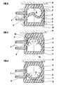
- the joint of the first example (1) has in the inflated state (FIG. 1) a maximum internal width (I) of 28 mm and a maximum internal height (H) of 24 mm. It has a sealed internal partition (2) with a developed width (L) equal to 36 mm, or 1.28 times the internal width (1), which separates the internal volume of the seal into two chambers, upper (3) and lower ( 4), of substantially equal volumes.
- This 3 mm thick corrugated partition (2) is connected, at its two ends, to the internal faces of the side walls (8) (9) of the 3.5 mm thick joint, at the same height of these internal faces.
- Each chamber (3) (4) is provided with at least one valve connection (7) which connects it to a source of pressurized fluid, so that the two chambers are subjected to the same pressure.
- These fittings are placed laterally (as shown) or on the back of the joint in the case of a joint closed on itself, often a circular joint, and they are placed at the end of the joint and fixed to the plates or plugs of elastomer which close them at their ends when they are linear joints.
- the seal (1) When the seal (1) is inflated (FIG. 2) to the same pressure of 1.3 bar for the two chambers, the internal height of the seal increases to become close to its internal width, while this internal width and the developed width of the interior partition (2) remains substantially constant.
- the corrugated interior partition (2) has an unstable equilibrium position between the chambers (3) and (4), it can occupy any position inside the joint (1) without significant constraint.
- the seal is arranged in a groove (12), cut, for example, in the fixed wall of a sealed enclosure (1), the sealing face (5) coming to bear on the flat surface (6) which is, for example, the door or the movable element of the sealed enclosure.
- the groove can be cut in the movable member.
- the chamber (3) loses its pressure and the partition (2) is subjected at a pressure difference compared to the other chamber (4) which remains intact.
- the partition (2) therefore deforms under the effect of the pressure of the chamber (4) and comes into contact with the vault (10) of the chamber (3) which is then at atmospheric pressure, or, at all less, at a pressure lower than that of the chamber (4).
- the seal is therefore preserved. It is possible, if necessary, upon detection of the perforation (11), to increase the pressure of the intact chamber (4).
- Figure 4 shows the opposite situation where the perforation (11) affected the lower chamber (4); the partition (2) then comes to bear on the internal wall of the foot (13) of the chamber (4) which has fallen to atmospheric pressure; the seal on the bearing surface (6) is, in the same way, preserved.
- the good support of the partition (2) is linked both to its ripple or additional initial developed width and to the additional elongation due to the pressure of the non-pierced chamber, and it is facilitated by the thickness of the partition (2) slightly less than that of the side walls (7) (8).
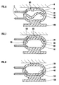
- the joint of the second example (100) is of oval type and has, in the non-inflated state (FIG. 5), a maximum internal width (I) of 107 mm and a maximum internal height (H) of 25 mm, ie a ratio I / H of 4.1, with a wall thickness of 10 mm. It comprises an internal watertight partition (20), of width developed at rest 107 mm, width equal to the internal width (1), and of thickness 7.5 mm.
- This internal partition (20) is connected to the internal faces of the side walls (80) (90) perpendicularly and substantially at mid-height of these side walls, the height of these walls can then be appreciated "rounded connection included" and it separates the internal volume into two chambers (30) and (40) having substantially the same volume.
- the inflated seal (100) ( Figure 6) has decreased in width and increased in height, and its bulkhead (20) is now corrugated.
- the prior undulation of this partition which prepares its support in the event of the piercing of one of the two chambers (30) or (40), is thus obtained by the deformation specific to this form of joint (neighboring I / H of 4) during its inflation.
- the two chambers are inflated at the same pressure and the watertight partition (20) has an unstable equilibrium position between these two chambers.
- Figures 7 and 8 show the same drilling situations as Figures 3 and 4: when the upper chamber (30) is pierced by a perforation (110) ( Figure 7), the interior partition (20) comes into contact with the arch (101) and supports this arch (101), while, when the lower chamber (40) is pierced by a perforation (110), the partition (20) comes to bear on the internal wall of the foot (130).
- This second type of seal is designed to be mounted by its foot (130) in a groove, of the “dovetail” type for example, while other forms of seals according to the invention, provided for operating pressures relatively low, require neither groove nor groove for their installation.
- the height of the joint is 130 mm (instead of 74 mm under pressure in the so-called “retracted” state).
- the height is still 120 mm, which is very largely sufficient to ensure, for example, the tightness of the slide rails of the cofferdams in the reactor pools, where the normal play can be, for example, of the order of 100 mm.
- this type of seal can withstand an internal pressure at least equal to 3 times its operating pressure in one or the other chamber or in both, due to the presence of the central partition limiting the forces on the side walls.
- the use of the internal partition seal, object of the invention notably improves the safety of sealing devices, in particular in the nuclear, aerospace, electronic and medical fields.
Landscapes
- Engineering & Computer Science (AREA)
- General Engineering & Computer Science (AREA)
- Physics & Mathematics (AREA)
- Architecture (AREA)
- Fluid Mechanics (AREA)
- Mechanical Engineering (AREA)
- Sealing Devices (AREA)
- Gasket Seals (AREA)
- Specific Sealing Or Ventilating Devices For Doors And Windows (AREA)
Description
- La présente invention concerne un joint d'étanchéité pneumatique en élastomère à sécurité améliorée, grâce à une cloison intérieure.
- Il est connu d'utiliser des joints pneumatiques rétractables, gonflables sous la pression d'un fluide, pour réaliser l'étanchéité entre deux enceintes, chambres, réservoirs, ou entre eux et l'extérieur. C'est le cas, notamment, dans les souffleries, chambres d'irradiation, véhicules amphibies, engins aériens et spatiaux, pour les portes ou bâtardeaux des piscines de désactivation de centrales nucléaires, les ateliers de retraitement de combustibles irradiés, les chambres dites «blanches» des industries électroniques et spatiales, les chambres stériles des hôpitaux.
- Toutes ces installations utilisent, conjointement aux parties métalliques ou en béton, ou autre matériau de structure, un ou plusieurs joints assurant l'étanchéité avec l'extérieur, par gonflage avec de l'air ou un fluide sous pression.
- De tels joints gonflables en élastomère ont été décrits dans le brevet FR-A-2188759 (GB-A-1440666) au nom de CEFILAC. De façon générale, ce type de joint comporte une face d'étanchéité, qui vient en appui sur la portée à rendre étanche, un pied, qui intervient dans la fixation du joint, et deux parois latérales.
- L'inconvénient majeur et bien connu de ce type de joint est que par perte de fluide moteur ou d'air, dès qu'une déchirure ou perforation de l'une des parois apparaît, le joint se trouve défaillant, il s'efface complètement par rétraction à l'interstice qu'il comblait entre le bâtardeau ou la porte et la partie à étancher et ne remplit plus sa fonction d'étanchéité. La demanderesse s'est proposé de trouver un moyen d'éviter cette défaillance.
- Le dispositif de sécurité, actuellement utilisé, consiste à placer à l'intérieur de la cavité du joint, une chambre à air ou une membrane imperméable contenant l'air ou le fluide moteur et suivant toutes les sollicitations du profil. Egalement, des insertions textiles, couramment utilisées dans les pneumatiques, renforcent les parois. Des déchirures ou des coupures sur la partie extérieure du joint n'entraînent pas forcément la perforation des parois ou de la membrane interne. C'est le système utilisé sur l'ensemble des pneumatiques de l'automobile, du cycle et du motocycle. Mais, lorsque la paroi du joint est fortement perforée, la chambre interne du joint l'est également puisqu'elle tapisse parfaitement l'intérieur du profilé; l'étanchéité est donc détruite, ce qui, dans la plupart des applications citées précédemment, est inacceptable, car il peut en résulter des conséquences dommageables pour la sécurité des personnes et des biens.
- Le brevet US-A-3 359 687 décrit par ailleurs un joint gonflable expansible pour système de pressurisation aéronautique, comprenant deux compartiments étanches à parois ondulées gonflables individuellement et séparés par une paroi. La hauteur du joint en service est obtenue par le gonflage à plus forte pression d'un seul compartiment, l'autre compartiment moins gonflé restant rétracté. En cas de crevaison du compartiment expansé, la pression de l'autre compartiment provoque son expansion, ce qui permet de maintenir la hauteur du joint. Dans ce fonctionnement, la cloison séparant les deux compartiments expansibles individuellement joue un rôle de séparation étanche inerte.
- L'invention se propose de résoudre le problème de la sécurité d'un joint gonflable en élastomère d'une façon différente de celle décrite par le brevet US-A-3 359 687, façon dans laquelle la cloison de séparation du joint en deux chambres intervient elle-même pour le maintien de l'étanchéité en cas de percement.
- De façon plus précise, le joint d'étanchéité pneumatique de sécurité en élastomère de l'invention comporte comme il est connu: une paroi d'étanchéité externe, un pied et deux parois latérales, qui définissent un volume interne de largeur interne maximale (I) comprise entre les deux parois latérales et de hauteur interne maximale (H) comprise entre la paroi d'étanchéité et le pied, et en outre une cloison intérieure étanche qui sépare le volume interne en deux chambres possédant chacune un moyen de mise en pression. Selon l'invention, la cloison intérieure étanche se raccorde aux parois latérales de sorte que les volumes respectifs des deux chambres qu'elle sépare soient dans un rapport compris entre 0,9 et 1,1, et de plus:
- - si I/H est compris entre 1 et 2, le joint ayant typiquement une cavité interne de forme en section droite circulaire ou rectangulaire, la largeur développée (L) de cette cloison étanche au repos est comprise entre 1,1 fois et 1,4 fois la largeur interne (t) ;
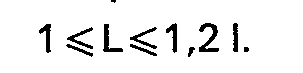
- - si I/H est compris entre 2 et 8, le joint ayanttypi- quement une cavité interne de forme en section droite ovale ou rectangulaire beaucoup plus large que haute, la largeur développée (L) de cette cloison étanche au repos, c'est-à-dire dans l'état non gonflé, est au moins égale à la largeur interne (I) tout en étant inférieure ou égale à 1,2 fois cette largeur interne, ce qui s'exprime plus simplement par:

- En cas de percement de l'une quelconque des deux chambres, la cloison intérieure étanche de l'invention se déforme sous l'effet de la pression de l'autre chambre et vient s'appuyer sur la paroi d'étanchéité externe ou la paroi de pied de la chambre percée de telle sorte que l'étanchéité que le joint assure est préservée.
- Le plus souvent, les deux chambres du joint de l'invention sont gonflées à des pressions égales et ont des épaisseurs de paroi comparables, de sorte que le rapport de leurs volumes respectifs reste sensiblement constant lorsqu'on passe de l'état rétracté ou de repos à l'état gonflé. Pour la sécurité du joint, dans laquelle la cloison intérieure étanche joue un rôle semblable vis-à-vis des deux chambres, il est alors préféré que les deux chambres aient des volumes sensiblement égaux avec des volumes respectifs dans un rapport compris entre 0,95 et 1,05.
- Conformément à l'invention, il faut que la largeur développée de la cloison intérieure étanche du joint, après déformation sous l'effet de la pression différentielle résultant du percement d'une chambre, soit suffisante pour que cette cloison vienne au contact et en appui sur la paroi de la chambre percée. La situation de la largeur développée de la cloison intérieure par rapport aux dimensions du volume intérieur, et en particulier par rapport à la largeur interne, se modifie entre l'état non gonflé et l'état gonflé lorsque le joint est plus large que haut, car alors lejointtend à s'arrondir au gonflage et de ce fait la cloison ondule si elle était plane à l'état non gonflé ou ondule davantage si elle était déjà ondulée. C'est à partir de cette situation à l'état gonflé que la déformation supplémentaire due à la pression différentielle en cas de percement doit premettre le maintien de l'étanchéité comme il vient d'être décrit. Au repos, le rapport de la largeur développée de la cloison intérieure à la largeur interne doit aussi de préférence être plus important lorsque le joint tendra moins à se déformer pour s'arrondir au gonflage, c'est-à-dire lorsque son rapport «I/H» diminuera en se rapprochant de 1.
- L'épaisseur de la cloison intérieure de l'invention doit en outre de préférence être suffisamment faible pour rendre son extension et ses déformations faciles, mais pas trop faible vis-à-vis des risques de percement ultérieurs. L'épaisseur des parois latérales, ou leur épaisseur la plus faible lorsque celles-ci présentent des variations, est prise comme point de repère, et il est préférable que l'épaisseur de la cloison intérieure au repos soit comprise entre 0,6 fois et 1 fois cette épaisseur de paroi latérale, et de façon optimale qu'elle soit comprise entre 0,7 fois et 0,9 fois cette épaisseur, de façon à permettre une bonne déformation préférentielle de la cloison intérieure étanche en cas de percement.
- Avec l'une ou l'autre de ces deux conditions d'épaisseur, deux cas sur lesquels portent les exemples qui suivent sont particulièrement intéressants en pratique:
- - si «I/H» est compris entre 1 et 1,5, la cloison intérieure étanche se raccorde de préférence aux deux parois latérales sensiblement à la même hauteur et elle a une largeur développée au repos comprise entre 1,2 fois et 1,4 fois la largeur interne (I);
- - si «I/H» est compris entre 3 et 5, la cloison intérieure étanche a une largeur développée au repos (L) égale à la largeur interne (I) et elle se raccorde à chacune des parois latérales selon un angle de 80 à 100° et sensiblement à la même hauteur de ces parois latérales.
-
- La figure 1 représente un premier exemple de joint selon l'invention, de section de forme sensiblement rectangulaire, à l'état non gonflé, en section droite.
- La figure 2 représente le même joint à l'état gonflé, en section droite.
- La figure 3 représente le même joint après percement de sa voûte d'étanchéité, en section droite.
- La figure 4 représente le même joint après percement du pied, en section droite.
- La figure 5 représente un deuxième exemple de joint selon l'invention, de section de forme sensiblement ovale, à l'état non gonflé, en section droite.
- La figure 6 représente ce deuxième joint à l'état gonflé, en section droite.
- La figure 7 représente ce deuxième joint après percement de sa voûte d'étanchéité, en section droite.
- La figure 8 représente ce même joint, après percement de la partie inférieure de sa paroi latérale, en section droite.
- Le joint du premier exemple (1 ) a à l'état gonflé (figure 1 ) une largeur interne maximale (I) de 28 mm et une hauteur interne maximale (H) de 24 mm. Il comporte une cloison intérieure étanche (2) de largeur développée (L) égale à 36 mm, soit 1,28 fois la largeur interne (1), qui sépare le volume interne du joint en deux chambres, supérieure (3) et inférieure (4), de volumes sensiblement égaux. Cette cloison (2) ondulée épaisse de 3 mm se raccorde, à ses deux extrémités, aux faces internes des parois latérales (8) (9) du joint épaisses de 3,5 mm, à la même hauteur de ces faces internes. Chaque chambre (3) (4) est munie d'au moins un raccord de valve (7) qui la relie à une source de fluide sous pression, de façon que les deux chambres soient soumises à une même pression. Ces raccords sont placés latéralement (comme représenté) ou au dos du joint dans le cas d'un joint fermé sur lui-même, souvent un joint circulaire, et ils sont placés en bout de joint et fixés aux plaques ou bouchons d'élastomère qui les obturent à leurs extrémités lorsqu'il s'agit de joints linéaires.
- Lorsque le joint (1 ) est gonflé (figure 2) à une même pression de 1,3 bar pour les deux chambres, la hauteur interne du joint augmente pour devenir voisine de sa largeur interne, tandis que cette largeur interne et la largeur développée de la cloison intérieure (2) restent sensiblement constantes. La cloison intérieure (2) ondulée a une position d'équilibre instable entre les chambres (3) et (4), elle peut occuper n'importe quelle position à l'intérieur du joint (1 ) sans contrainte notable.
- Dans le cas particulier représenté sur la figure 2, le joint est disposé dans une gorge (12), taillée, par exemple, dans la paroi fixe d'une enceinte étanche (1 ), la face d'étanchéité (5) venant en appui sur la portée plane (6) qui est, par exemple, la porte ou l'élément mobile de l'enceinte étanche. La disposition inverse est également possible, c'est-à-dire, que la gorge peut être taillée dans l'élément mobile.
- Lorsqu'une des parties du joint, par exemple la voûte d'étanchéité (10) se trouve perforée ou déchirée (11) (cas de la figure 3) la chambre (3) perd sa pression et la cloison (2) se trouve soumise à une différence de pression par rapport à l'autre chambre (4) restée intacte. La cloison (2) se déforme donc sous l'effet de la pression de la chambre (4) et vient au contact de la voûte (10) de la chambre (3) qui se trouve alors à la pression atmosphérique, ou, tout au moins, à une pression inférieure à celle de la chambre (4). L'étanchéité est donc préservée. On peut, le cas échéant, sur détection de la perforation (11), augmenter la pression de la chambre intacte (4).
- La figure 4 montre la situation inverse où la perforation (11) a affecté la chambre inférieure (4) ; la cloison (2) vient alors en appui sur la paroi interne du pied (13) de la chambre (4) qui est retombée à la pression atmosphérique; l'étanchéité sur la portée (6) est, de la même façon, préservée. Dans cette situation comme dans la précédente, la bonne mise en appui de la cloison (2) est liée à la fois à son ondulation ou supplément de largeur développée initial et à l'allongement supplémentaire dû à la pression de la chambre non percée, et elle est facilitée par l'épaisseur de la cloison (2) un peu plus faible que celle des parois latérales (7) (8).
- Le joint du deuxième exemple (100) est de type ovale et a à l'état non gonflé (figure 5) une largeur interne maximale (I) de 107 mm et une hauteur interne maximale (H) de 25 mm, soit un rapport I/H de 4,1, avec une épaisseur de paroi de 10 mm. Il comporte une cloison intérieureétanche (20), de largeur développée au repos 107 mm, largeur égale à la largeur interne (1), et d'épaisseur 7,5 mm. Cette cloison intérieure (20) se raccorde aux faces internes des parois latérales (80) (90) de façon perpendiculaire et sensiblement à mi-hauteur de ces parois latérales, la hauteur de ces parois pouvant alors être appréciée «arrondis de raccordement compris» et elle sépare le volume interne en deux chambres (30) et (40) ayant sensiblement le même volume.
- Le joint (100) gonflé (figure 6) a diminué de largeuret augmenté de hauteur, etsa cloison étanche (20) est maintenant ondulée. L'ondulation préalable de cette cloison, qui prépare sa mise en appui en cas de percement de l'une des deux chambres (30) ou (40), est ainsi obtenue par la déformation propre à cette forme de joint (I/H voisin de 4) lors de son gonflage. Comme dans le premier exemple, les deux chambres sont gonflées à même pression et la cloison étanche (20) a une position d'équilibre instable entre ces deux chambres. Les figures 7 et 8 représentent les mêmes situations de percement que les figures 3 et 4: lorsque la chambre supérieure (30) est percée par une perforation (110) (figure 7), la cloison intérieure (20) vient en contact avec la voûte (101 ) et soutient cette voûte (101), tandis que, lorsque la chambre inférieure (40) est percée par une perforation (110), la cloison (20) vient s'appuyer sur la paroi interne du pied (130).
- Ce deuxième type de joint est prévu pour être monté par son pied (130) dans une rainure, du genre «queue d'aronde» par exemple, tandis que d'autres formes de joints selon l'invention, prévus pour des pressions de service relativement basses, ne nécessitent ni gorge, ni rainure pour leur mise en place.
- On a réalisé par extrusion une série de joints, de deux mètres de long, en polymère «SBR» (styrène-butadiène-rubber), conformes au dernier exemple, et ayant donc au repos une section schématisée par la figure 5, et à l'état gonflé une section schématisée par la figure 6. Au repos, à l'état rétracté, les joints ont une largeur de 130 mm et une hauteur de 75 millimètres. En vue de tester le comportement de la cloison interne, et sa réponse à la perte de pression de l'une ou l'autre chambre, on a relié les joints à tester par les raccords (7) à un système pneumatique asservi de façon à réaliser des cycles successifs de:
- - mise en équipression des deux chambres sous 2 bars,
- - dégonflage d'une chambre-ce qui provoque la chute de la pression de 2 à environ 1 bar dans la chambre restée en pression - dont le volume se trouve peu à peu doublé,
- - remise à la pression de 2 bars de la chambre restée en pression,
- - regonflage à 2 bars de la chambre dégonflée, et dégonflage de la chambre qui se trouvait en pression,
- On a noté que, lorsque les deux chambres sont en pression, la hauteur du joint est de 130 mm (au lieu de 74 mm sous pression à l'état dit «rétracté»). Lorsqu'une chambre est dégonflée et l'autre à une pression de 2 bars, la hauteur est encore de 120 mm, ce qui est très largement suffisant pour assurer, par exemple, l'étanchéité des glissières de bâtardeaux dans les piscines de réacteurs, où le jeu normal peut être, par exemple, de l'ordre de 100 mm.
- Après 15000 cycles alternés, aucune altération de l'étanchéité du joint et de la cloison n'est apparue, la hauteur du joint gonflé, avec une chambre dégonflée, restant égale à 120 millimètres, et la hauteur, à l'état rétracté, égale à 75 mm.
- En outre, ce type de joint peut résister à une pression interne au moins égale à 3 fois sa pression de service dans l'une ou l'autre chambre ou dans les deux, du fait de la présence de la cloison médiane limitant les efforts sur les parois latérales.
- La mise en oeuvre du jointà cloison interne, objet de l'invention, améliore notablement la sécurité des dispositifs d'étanchéité, notamment dans les domaines nucléaire, aérospatial, électronique et médical.
et ainsi de suite.
Claims (6)
Applications Claiming Priority (2)
| Application Number | Priority Date | Filing Date | Title |
|---|---|---|---|
| FR8413681 | 1984-08-30 | ||
| FR8413681 | 1984-08-30 |
Publications (2)
| Publication Number | Publication Date |
|---|---|
| EP0179722A1 EP0179722A1 (fr) | 1986-04-30 |
| EP0179722B1 true EP0179722B1 (fr) | 1987-12-09 |
Family
ID=9307467
Family Applications (1)
| Application Number | Title | Priority Date | Filing Date |
|---|---|---|---|
| EP85420155A Expired EP0179722B1 (fr) | 1984-08-30 | 1985-08-28 | Joint d'étanchéité pneumatique de sécurité en élastomère à cloison intérieure |
Country Status (4)
| Country | Link |
|---|---|
| US (1) | US4624465A (fr) |
| EP (1) | EP0179722B1 (fr) |
| JP (1) | JPS6174975A (fr) |
| DE (1) | DE3561175D1 (fr) |
Families Citing this family (24)
| Publication number | Priority date | Publication date | Assignee | Title |
|---|---|---|---|---|
| US5048570A (en) * | 1986-04-21 | 1991-09-17 | Combustion Engineering Inc. | Multisectioned nozzle dam |
| DE3636600A1 (de) * | 1986-10-28 | 1988-05-05 | Hoesch Maschinenfabrik Ag | Heizpresse zum verpressen von technischen laminaten |
| DE3813573C1 (fr) * | 1988-04-22 | 1989-12-07 | Effem Gmbh, 2810 Verden, De | |
| US4993722A (en) * | 1988-12-07 | 1991-02-19 | Npc, Inc. | Apparatus and method for improved pipe to manhole sealing |
| FR2665499B1 (fr) * | 1990-07-10 | 1994-01-28 | Joint Francais | Dispositif d'etancheite a joint gonflable pour porte ou panneau mobile. |
| GB2247055A (en) * | 1990-07-19 | 1992-02-19 | Yorkshire Water Services Ltd | Seals for use in pipeline systems |
| US5580068A (en) * | 1990-07-27 | 1996-12-03 | Npc, Inc. | Liquid filled seal |
| US5102150A (en) * | 1991-02-19 | 1992-04-07 | The United States Of America As Represented By The Administrator Of The National Aeronautics And Space Administration | Pressure vessel flex joint |
| GB9107864D0 (en) * | 1991-04-12 | 1991-05-29 | Raychem Sa Nv | Environmental sealing |
| US5341726A (en) * | 1993-03-31 | 1994-08-30 | Watson M Burnell | Piston for tank |
| US5941536A (en) * | 1998-02-12 | 1999-08-24 | Envirotech Pumpsystems, Inc. | Elastomer seal for adjustable side liners of pumps |
| US6206248B1 (en) | 1999-04-16 | 2001-03-27 | James L. Popp | Dispensing piston for commodity container |
| DE19940235C1 (de) * | 1999-08-25 | 2000-09-28 | Neugart Gmbh & Co | Getriebe, insbesondere Planetengetriebe, mit Druckausgleich |
| US6481927B2 (en) | 2001-04-11 | 2002-11-19 | Lester Kent Rhodes | Assembly and method for joining a drain pipe and a catch basin |
| US20100132264A1 (en) * | 2008-12-01 | 2010-06-03 | Steven Campbell | Bi-flow inflatable door seals |
| FR2951518B1 (fr) * | 2009-10-15 | 2014-09-05 | Jose Collados | Dispositif d'etancheite et son procede de gonflage. |
| KR20120126064A (ko) * | 2010-01-28 | 2012-11-20 | 배트 홀딩 아게 | 챔버벽의 개구부를 폐쇄하기 위한 장치 |
| US20110241342A1 (en) * | 2010-04-01 | 2011-10-06 | Skellern Michael J | Pipe Repair Clamp with Self Pressurizing Seal |
| SE539200C2 (en) * | 2015-09-09 | 2017-05-09 | BAE Systems Hägglunds AB | Sealing arrangement for an amphibious vehicle |
| US11592106B2 (en) * | 2018-04-29 | 2023-02-28 | Sean P. Thomas | Hollow annular seal for equipment disposed in a subsea environment |
| SG11202009263YA (en) * | 2018-05-24 | 2020-10-29 | Halliburton Energy Services Inc | Rolling seal for transfer of pressure in a downhole tool |
| GB201908783D0 (en) * | 2019-06-19 | 2019-07-31 | Tokamak Energy Ltd | Metal sealing ring and method of forming a metal-to-metal seal |
| CN110388525B (zh) * | 2019-08-16 | 2024-06-11 | 钱建统 | 一种适用于高压风炮的气动快速接头 |
| CN112902541B (zh) * | 2021-02-02 | 2022-06-17 | 深圳市均佳机电设备有限公司 | 一种用于可变容量冷库的密封保温系统 |
Citations (1)
| Publication number | Priority date | Publication date | Assignee | Title |
|---|---|---|---|---|
| US3359687A (en) * | 1964-08-17 | 1967-12-26 | Haveg Industries Inc | Expansible seal |
Family Cites Families (8)
| Publication number | Priority date | Publication date | Assignee | Title |
|---|---|---|---|---|
| US2700196A (en) * | 1950-12-28 | 1955-01-25 | Panhard & Levassor | Inflatable weather strip for mounting vehicle windows in frames |
| US3178779A (en) * | 1962-06-28 | 1965-04-20 | North American Aviation Inc | Multi-cell inflatable seal |
| US3262707A (en) * | 1963-04-26 | 1966-07-26 | Williams Res Corp | High pressure seal used in conjunction with regenerator |
| US3161229A (en) * | 1963-06-19 | 1964-12-15 | Koppers Co Inc | Seal configuration for folding partition |
| DE1187871B (de) * | 1963-07-02 | 1965-02-25 | Weill & Reineke | Dichtungsprofil aus elastischem Material |
| FR2243619A5 (fr) * | 1973-09-06 | 1975-04-04 | Joint Francais | |
| JPS53129757A (en) * | 1977-04-19 | 1978-11-13 | Doryokuro Kakunenryo | Sealing of moving member with hollow packing |
| JPS57166U (fr) * | 1980-06-02 | 1982-01-05 |
-
1985
- 1985-08-26 US US06/769,028 patent/US4624465A/en not_active Expired - Fee Related
- 1985-08-28 EP EP85420155A patent/EP0179722B1/fr not_active Expired
- 1985-08-28 DE DE8585420155T patent/DE3561175D1/de not_active Expired
- 1985-08-29 JP JP60190870A patent/JPS6174975A/ja active Granted
Patent Citations (1)
| Publication number | Priority date | Publication date | Assignee | Title |
|---|---|---|---|---|
| US3359687A (en) * | 1964-08-17 | 1967-12-26 | Haveg Industries Inc | Expansible seal |
Also Published As
| Publication number | Publication date |
|---|---|
| JPS6174975A (ja) | 1986-04-17 |
| US4624465A (en) | 1986-11-25 |
| JPH0469310B2 (fr) | 1992-11-05 |
| EP0179722A1 (fr) | 1986-04-30 |
| DE3561175D1 (en) | 1988-01-21 |
Similar Documents
| Publication | Publication Date | Title |
|---|---|---|
| EP0179722A1 (fr) | Joint d'étanchéité pneumatique de sécurité en élastomère à cloison intérieure | |
| EP2243678B1 (fr) | Ensemble de joints pour une porte | |
| EP0003091B1 (fr) | Joint annulaire | |
| KR20000069958A (ko) | 신속히 분리 가능한 창유리 | |
| FR2558917A1 (fr) | Garniture d'etancheite pour reduire un flux gazeux dans l'espace compris entre deux elements mobiles | |
| EP1985471A2 (fr) | Pneumatique à bruit de roulement réduit | |
| FR2925140A1 (fr) | Joint d'etancheite superplastique, de preference pour systeme a cellules electrochimiques | |
| EP1206357A1 (fr) | Ensemble d'une jante et d'un appui de soutien | |
| US20120085472A1 (en) | Tube System | |
| FR2705925A1 (fr) | Joint de porte pour véhicule automobile. | |
| BE1012962A3 (fr) | Joint metallique statique et procede de fabrication. | |
| US20150090007A1 (en) | Method for detecting leaks in aircraft wings | |
| FR2620783A1 (fr) | Joint d'etancheite pour tubage | |
| CA2372588A1 (fr) | Ensemble de montage d'un pneumatique sur un moyeu | |
| CN118294082B (zh) | 一种水利水电施工用管道对接检测设备及方法 | |
| FR2723036A1 (fr) | Ensemble pneumatique sans chambre a air pour vehicules deux roues comportant une structure annulaire elastique et deformable | |
| JP2003200720A (ja) | タイヤの突き刺し爆発防止構造 | |
| FR2519912A1 (fr) | Dispositif de montage d'un pneu avec manchon de verrouillage | |
| US10118708B2 (en) | Evacuation slide with beam structure comprising four-point cross section | |
| FR2745622A1 (fr) | Joint et son procede de montage par clipage | |
| JP2857098B2 (ja) | 浮体ユニットの洋上接合方法 | |
| FR2683248A1 (fr) | Armature tubulaire gonflable de securite pour des tentes et des articles analogues. | |
| EP0613793B1 (fr) | Pneumatique à deux bandes de roulement et rainure de forme adaptée | |
| KR100920059B1 (ko) | 스턴튜브 부시유니트 및 그 설치방법 | |
| JPH0639317Y2 (ja) | フランジ管接合部の耐圧試験装置 |
Legal Events
| Date | Code | Title | Description |
|---|---|---|---|
| PUAI | Public reference made under article 153(3) epc to a published international application that has entered the european phase |
Free format text: ORIGINAL CODE: 0009012 |
|
| AK | Designated contracting states |
Kind code of ref document: A1 Designated state(s): DE FR GB IT SE |
|
| 17P | Request for examination filed |
Effective date: 19860520 |
|
| 17Q | First examination report despatched |
Effective date: 19870422 |
|
| GRAA | (expected) grant |
Free format text: ORIGINAL CODE: 0009210 |
|
| AK | Designated contracting states |
Kind code of ref document: B1 Designated state(s): DE FR GB IT SE |
|
| ITF | It: translation for a ep patent filed | ||
| REF | Corresponds to: |
Ref document number: 3561175 Country of ref document: DE Date of ref document: 19880121 |
|
| GBT | Gb: translation of ep patent filed (gb section 77(6)(a)/1977) | ||
| REG | Reference to a national code |
Ref country code: FR Ref legal event code: TP |
|
| PLBE | No opposition filed within time limit |
Free format text: ORIGINAL CODE: 0009261 |
|
| STAA | Information on the status of an ep patent application or granted ep patent |
Free format text: STATUS: NO OPPOSITION FILED WITHIN TIME LIMIT |
|
| 26N | No opposition filed | ||
| ITTA | It: last paid annual fee | ||
| EAL | Se: european patent in force in sweden |
Ref document number: 85420155.5 |
|
| REG | Reference to a national code |
Ref country code: FR Ref legal event code: CA |
|
| PGFP | Annual fee paid to national office [announced via postgrant information from national office to epo] |
Ref country code: GB Payment date: 19960613 Year of fee payment: 12 |
|
| PGFP | Annual fee paid to national office [announced via postgrant information from national office to epo] |
Ref country code: FR Payment date: 19960716 Year of fee payment: 12 |
|
| PGFP | Annual fee paid to national office [announced via postgrant information from national office to epo] |
Ref country code: DE Payment date: 19960722 Year of fee payment: 12 |
|
| PGFP | Annual fee paid to national office [announced via postgrant information from national office to epo] |
Ref country code: SE Payment date: 19960723 Year of fee payment: 12 |
|
| REG | Reference to a national code |
Ref country code: GB Ref legal event code: 732E |
|
| PG25 | Lapsed in a contracting state [announced via postgrant information from national office to epo] |
Ref country code: GB Free format text: LAPSE BECAUSE OF NON-PAYMENT OF DUE FEES Effective date: 19970828 |
|
| PG25 | Lapsed in a contracting state [announced via postgrant information from national office to epo] |
Ref country code: SE Free format text: LAPSE BECAUSE OF NON-PAYMENT OF DUE FEES Effective date: 19970829 |
|
| GBPC | Gb: european patent ceased through non-payment of renewal fee |
Effective date: 19970828 |
|
| PG25 | Lapsed in a contracting state [announced via postgrant information from national office to epo] |
Ref country code: FR Free format text: LAPSE BECAUSE OF NON-PAYMENT OF DUE FEES Effective date: 19980430 |
|
| PG25 | Lapsed in a contracting state [announced via postgrant information from national office to epo] |
Ref country code: DE Free format text: LAPSE BECAUSE OF NON-PAYMENT OF DUE FEES Effective date: 19980501 |
|
| EUG | Se: european patent has lapsed |
Ref document number: 85420155.5 |
|
| REG | Reference to a national code |
Ref country code: FR Ref legal event code: ST |