EP0179601A2 - Verfahren zur Vermessung mittels Mikrowellenreflexion - Google Patents
Verfahren zur Vermessung mittels Mikrowellenreflexion Download PDFInfo
- Publication number
- EP0179601A2 EP0179601A2 EP85307342A EP85307342A EP0179601A2 EP 0179601 A2 EP0179601 A2 EP 0179601A2 EP 85307342 A EP85307342 A EP 85307342A EP 85307342 A EP85307342 A EP 85307342A EP 0179601 A2 EP0179601 A2 EP 0179601A2
- Authority
- EP
- European Patent Office
- Prior art keywords
- antenna
- radiation
- ground
- antennas
- signals
- Prior art date
- Legal status (The legal status is an assumption and is not a legal conclusion. Google has not performed a legal analysis and makes no representation as to the accuracy of the status listed.)
- Granted
Links
Images


Classifications
-
- G—PHYSICS
- G01—MEASURING; TESTING
- G01V—GEOPHYSICS; GRAVITATIONAL MEASUREMENTS; DETECTING MASSES OR OBJECTS; TAGS
- G01V3/00—Electric or magnetic prospecting or detecting; Measuring magnetic field characteristics of the earth, e.g. declination, deviation
- G01V3/12—Electric or magnetic prospecting or detecting; Measuring magnetic field characteristics of the earth, e.g. declination, deviation operating with electromagnetic waves
-
- G—PHYSICS
- G01—MEASURING; TESTING
- G01S—RADIO DIRECTION-FINDING; RADIO NAVIGATION; DETERMINING DISTANCE OR VELOCITY BY USE OF RADIO WAVES; LOCATING OR PRESENCE-DETECTING BY USE OF THE REFLECTION OR RERADIATION OF RADIO WAVES; ANALOGOUS ARRANGEMENTS USING OTHER WAVES
- G01S13/00—Systems using the reflection or reradiation of radio waves, e.g. radar systems; Analogous systems using reflection or reradiation of waves whose nature or wavelength is irrelevant or unspecified
- G01S13/02—Systems using reflection of radio waves, e.g. primary radar systems; Analogous systems
- G01S13/04—Systems determining presence of a target
-
- G—PHYSICS
- G01—MEASURING; TESTING
- G01S—RADIO DIRECTION-FINDING; RADIO NAVIGATION; DETERMINING DISTANCE OR VELOCITY BY USE OF RADIO WAVES; LOCATING OR PRESENCE-DETECTING BY USE OF THE REFLECTION OR RERADIATION OF RADIO WAVES; ANALOGOUS ARRANGEMENTS USING OTHER WAVES
- G01S7/00—Details of systems according to groups G01S13/00, G01S15/00, G01S17/00
- G01S7/02—Details of systems according to groups G01S13/00, G01S15/00, G01S17/00 of systems according to group G01S13/00
- G01S7/024—Details of systems according to groups G01S13/00, G01S15/00, G01S17/00 of systems according to group G01S13/00 using polarisation effects
- G01S7/026—Details of systems according to groups G01S13/00, G01S15/00, G01S17/00 of systems according to group G01S13/00 using polarisation effects involving the transmission of elliptically or circularly polarised waves
-
- G—PHYSICS
- G01—MEASURING; TESTING
- G01S—RADIO DIRECTION-FINDING; RADIO NAVIGATION; DETERMINING DISTANCE OR VELOCITY BY USE OF RADIO WAVES; LOCATING OR PRESENCE-DETECTING BY USE OF THE REFLECTION OR RERADIATION OF RADIO WAVES; ANALOGOUS ARRANGEMENTS USING OTHER WAVES
- G01S13/00—Systems using the reflection or reradiation of radio waves, e.g. radar systems; Analogous systems using reflection or reradiation of waves whose nature or wavelength is irrelevant or unspecified
- G01S13/88—Radar or analogous systems specially adapted for specific applications
- G01S13/885—Radar or analogous systems specially adapted for specific applications for ground probing
Definitions
- This invention relates to detector and survey systems utilising polarisable ground penetrating radiation. More particularly this invention relates to apparatus and a method for detecting both metal and non-metal objects or structures, such as pipelines which are buried in the ground wherein the apparatus can be operated in an automatic way so as to enable maps to be produced of the buried objects detected.
- Inductive techniques are available for locating buried metallic structures. However, such techniques cannot be used for detecting nonmetallic objects such as plastic pipes.
- Techniques based on RADAR have been used for geophysical surveys in which pulsed electromagnetic radiation is transmitted from a transmitting antenna located close to the ground. Any change in the dielectric properties of the sub-strata produces a reflection of the transmitted pulse which is received by a receiving antenna located above ground. The received waveform contains an echo signal at a time related to the depth of the change in strata.
- This technique can be employed for locating buried structures, the structure producing the echo signal. However, the echo can be very small on account of the high attenuation of the ground. Significantly larger signals result from signals off the ground and additionally direct breakthrough of energy can occur between the antennas. Thus the derived signal can be almost completely masked by unwanted 'clutter signals".
- the orientation may be discovered if the polarisation of the incident radiation can be rotated in a known way, while the clutter may be reduced by passing the received signals through a filter designed according to the characteristics of the signal being sought and the statistical properties of the unwanted clutter.
- the transmitting and receiving antennas are electrically orthogonal (which does not necessarily imply geometrically orthogonal) the radiated wave from the transmitting antenna has no effect on the receiving one, even if the two are very close or have a common centre.
- Electrically orthogonal antennas have the advantage that any planar, uniform dielectric discontinuity which a perpendicular to the direction of the incident radiation produces a reflected signal which gives rise to no output from the receiving antenna.
- a system is less sensitive to the presence of the ground surface than would be a pair of parallel antennas to transmit and receive the radiation.
- the ground surface is not a planar uniform dielectric discontinuity so that there is always some component due to the presence of the ground surface.
- the term 'orthogonal' will be taken to mean 'as near electrically orthogonal as is conveniently practical'.
- a further advantage of an orthogonal antenna pair is that target objects which are long and thin, or which preferentially scatter radiation polarised in one direction, result in an output from the receiving antenna which varies with the orientation of the object relative to that of the antenna system.
- the signal is a minimum (zero if there are no interfering signals) when the target's principal axis is parallel or perpendicular to the direction of the transmitted polarisation, and is a maximum when that axis is at 45° to either of these directions.
- circular polarisation is transmitted there is no amplitude variation with relative orientation, but the phase of the received signal varies with orientation.
- phase variation In general, for elliptically polarised radiation there is both an amplitude and a phase variation.
- One way of effecting the rotation of the polarisation of the energy transmitted into the ground and incident upon any buried object is by mechanical rotation of an assembly consisting of a pair of orthogonal concentred antennas.
- the symmetry of the geometry dictates that the received signal can consist of up to three components: one which is independent of orientation, one which is singly periodic in antenna rotation and one which is doubly periodic.
- the first arises from breakthrough because of inherent non-orthogonality in the design.
- the second is due to any non-coincidence of the mechanical centre of rotation and the electrical centre of either of the antennas, while the third arises from any scatterer, in the near or far field, which gives preferential scattering of one polarisation.
- the basic data required for polarisation processing is a set of measurements made as the antenna assembly is rotated above the ground location under investigation.
- the most obvious way of achieving this is to mount the antenna suspended from a suitable turntable and to record the received waveform at rotation intervals of 10° , say.
- one pair of measurements made at any known angular separation (other than an integer multiple of 90°) is adequate to describe the complete variation. (A convenient separation is 45° or 60°).
- the time waveform which exists at an arbitrary angle X relative to some reference direction on the ground is given by F(t) - A(t) + B(t)sinX + C(t)cosX + D(t)sin2X + E(t)cos2X, where A,B,C,D, and E are functions derived from the five measurements as follows. Let the five measured time waveforms be P(t), Q(t), R(t), S(t) and T(t) measured at 0, 45, 90, 135 and 180 degrees, respectively.
- apparatus for locating buried objects including an antenna assembly connected to a pulse generator and to a receiver which converts echo signals into data representative of the buried object.
- the antenna assembly comprises a pair of orthogonally co-located two-terminal antennas.
- pulsed radiation is transmitted into the ground from one of the antennas and any echo signals indicative of a target, are received on the other orthogonally located antenna. It is contended that detection of a long thin object, such as a pipe, can be confirmed by making at least three measurements viz. two measurements orthogonal with respect to each other (by mechanically rotating the assembly) when the echo response is zero on the receive antenna and one at 45° when the echo response is at a maximum.
- a further disadvantage of this apparatus as taught in UK Patent Specification 1532710 is that total reliance is placed on the antenna design for suppression of the breakthrough signal and no provision is made in the instrumentation for distinguishing between the breakthrough which arises from ground surface variations and the reflected signals from shallower targets, since both exhibit the same phase reversal which the instrument detects. Nor is allowance made for the singly periodic component of the received signal which can lead to erroneous interpretation of the results.
- Known equipment including that described above, suffers from the problems of ground contact requirements, which are that if an antenna system is designed to be ground contacting for efficient transduction then performance is severely affected by imperfect contact, whereas those which are operated with non-ground-contacting antennas in the interests of mobility are affected by local high spots in the ground surface.
- the present invention seeks to avoid the disadvantages of the prior art and proposes a method and antenna assembly for use therewith in which buried objects, and particularly long thin objects such as pipes can be located, the position determined, and the pipe direction ascertained, by taking measurements from a single point, without mechanical movement of the antenna, and thereby allowing a better suppression of spurious signals and a reduction in false indications.
- a method for Locating buried objects which method includes the steps of transmitting into the ground polarisable radiation, receiving reflected ;ignals, indicative of said objects, incident upon at least two :o-located angularly disposed transducers and comparing the signals thus received, said radiation being transmitted from a transducer source which is co-located but angularly disposed with respect to each receiver transducer.
- the invention also provides an antenna assembly suitable for use in the aethod of the invention, said assembly comprising an arrangement of at least three, co-located, two-terminal antennas wherein the antennas are angularly disposed with respect to each other around a common point and each antenna is adapted to be capable of selectively transmitting polarisable radiation into the ground and receiving reflected radiation from out of the ground.
- the invention also provides an antenna assembly for use in transmitting and receiving ground penetrating radiation having a plurality of antenna arms adapted and arranged to transmit and receive radiation into the ground characterised in that the arms have, on at least the surface nearest the ground, a cladding of a substantially lossless dielectric material, the relative permitivity of said dielectric being at least 3.5 and the thickness of said coating being at least ⁇ d/20 where ⁇ d is the wavelength of lowest frequency of the radiation to be transmitted from the antenna.
- the antenna will be of substantially planar construction and will have parallel upper and lower surfaces.
- the coating thickness should be at leaet ⁇ d/20 thick (where d is defined above). Preferably, the thickness should be not more than about ⁇ d/5. However, where the antenna is designed to transmit (and receive) a range of frequencies, the thickness should preferably not exceed A/3 where is the wavelength of the highest frequency of the range.
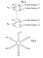
- Figure 1 shows one pair of orthogonal, two-limbed antennas, 1,1' and 2,2' with a second like pair interleaved between them 3,3' and 4,4'.
- the antenna limbs are planar metal structures mounted on a thin, non-conductive dielectric support sheet of relative permittivity typically 2.5, which can radiate and receive essentially linearly polarised radiation.
- the antennas are fed at their centres through wide-band balun units, one of Which is shown diagramatically in Figure lb.
- the straight dipole limbs are replaced by planar spiral arms 5,5'; 6,6'; 7,7'; 8,8', which design is known to allow of a broader frequency range of operation, and to transmit approximately circulary polarised radiation.
- a convenient way of terminating the outer ends of the antennas is with chains of resistors joining each metal limb to its immediate neighbours.
- Each chain would be identical and consist of a set of resistors having lower values adjacent to the conductors and higher values midway between the said conductors.
- the pair of antennas 1,1' and 2,2' is fed with voltage generators 9 and 10 having output rms voltages V 1 and V 2 , respectively. It is possible to transmit radiation from both simultaneously such that, if V 1 and V 2 are co-phased, the perceived polarisation remote from the antennas is substantially linear and is inclined at an angle to the axis of the antenna 1,1' given by In this way the transmitted polarisation can be rotated to any value of ⁇ .
- Vg and V 10 can be voltage generators with a constant rms voltage; attenuators, preferably electronically controlled, are incorporated between the said generators and the antennas 1,1' and 2,2' so as to enable the voltages applied to the antennas to be set in the desired ratio.
- the radiation received by 3,3' and 4,4' can be attenuated appropriately so as to make that pair sensitive to linearly polarised radiation at any angle, preferablyl + 90°.
- phase shift networks into the transmit and receive circuitry allows any polarisation state between linear and circular to be transmitted.
- phase shift components are not ordinarily available to cover a wide range of frequencies, such as is desired for pipe location applications. Consequently it is preferred that an antenna design be used which generates the required polarisation automatically.
- the antenna consisting of lines 5,5' in Figure 2 radiates a nearly circularly polarised signal.
- the design of Figure 3 gives approximately linearly polarised radiation but it will operate over a wider range of frequencies than the antenna shown in Figure 1.
- the requirement of only two measurements separated by a known angle means that variation of the polarisation direction by adjustment of the voltage ratio V 2 /V 1 need not be used.
- microwave switches 15, 16 can be used so as to excite 1,1' as transmitter and 2,2' as receiver, followed by 3,3' as transmitter and 4,4' as receiver, at an orientation of 45° to the first.
- these two measurements would be adequate to represent the entire angular dependence of the received waveform and allow a reconstruction of the results which would have been obtained if the antenna pair 1,1' and 2,2', say, were mechanically rotated.
- An alternative method of operation of two pairs of antennas is to transmit equal signals on 1,1' and 3,3' and to receive on 2,2', or vice-versa, or by any other a range of combinations possible.
- Suitable microwave switching circuitry is preferably provided for only the transmitting antennas because the received signals can be selected and combined as necessary by signal processing software.
- Figure 5 shows a six limb antenna 17,17', 18,18', 19,19'. Transmission is on limbs 17,17', say, and reception is on 18,18' and 19,19' together. Subtraction of the received signals results in the effective position of the receiving antenna being perpendicular to 17,17'. The subtraction is in fact an addition since because it is a subtraction with a phase reversal. A second measurement is made by transmission on 18,18' and reception on 17,17' and 19,19' together. An addition gives the required result, at 60° to the first. These measurements are also adequate to represent the variation as though there were mechanical rotation.
- An advantage of electronic rotation as described is that there is no singly periodic term present provided that the antenna patterns are made symmetrically.
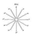
- a third pair of antennas is introduced, as shown in Figure 6. This allows three independent samples to be made of the sinusoidal variation of the received signal, and hence any angle-invariant term can be found. For more complicated antenna designs (ie non-dipole), however, the presence of twelve limbs around the circumference may present problems in construction.
- a measurement is made of the breakthrough signal with the antenna design of Figures 1-3 at two orientations differing by 90° using mechanical rotation and the difference waveform is stored.
- Another waveform can be obtained and stored for the other pair of orthogonal antennas, and the appropriate one is subtracted from all subsequent measurements made under conditions of electronic rotation.
- the stored waveforms depend upon the soil type (in particular on the permittivity), but from the nature of the measurement they are not subject to the local fluctuations in the vicinity of the antenna - these latter cause doubly-periodic variations which show up as clutter in the time waveform.
- an adaptive set of weights has to be applied to the received signals from two antennas, such as 18,18' and 19,19' so as to cancel completely the breakthrough signal seen when the antennas are directed at the sky (an assumed uniform dielectric environment) and transmission is from antenna 17,17.
- the weighting function is expanded in time so as to take account of the new dielectric environment, with an expansion factor determined, for example, by the scaling observed in the reflection function. Any observed breakthrough signal must be due solely to the variations in the dielectric properties of the ground and so the angle-invariant contribution is suppressed.
- the method and apparatus of the invention whilst utilising polarisation of the electromagnetic radiation, does not depend on the use of one particular polarisation state.
- the electromagnetic radiation scattered from targets such as pipes will be substantially linearly polarised in the direction of the major (long) axis, provided that the target width is I much less than the wavelength of the radiation.
- the antenna be planar since this offers the advantage that it can be placed either in contact with the ground or be separated by only a small distance. In both cases, radition is directed substantially into the ground to provide a good coupling which minimises clutter due to multiple ground reflections. It is also preferred that the antenna metal be fixed in intimate contact with a lossless uniform dielectric slab whose relative permittivity (E r ) is approximately the same as that of the ground (typically greater than 3.5). However, for ground of high permittivity Er should be preferably within a factor of 2 compared with that of ground.
- the dielectric slab is positioned between the antenna metal and the ground surface, although there is no need for contact with the ground surface; preferably there is a gap to facilitate antenna mobility.
- the slab should be preferably circular and of a sufficient size that no antenna metal projects beyond its edges.
- ⁇ d is the wavelength in the dielectric corresponding to the lowest frequency at which the antenna is designed to operate in the absence of the dielectric.
- the electrical size of the antenna is increased.
- E r m 10 the factor of increase was found to be approximately 1.6, for dielectric of thickness 1.25 cm or greater, so that an antenna whose operational frequency range without the dielectric layer was 300 MHz to 2 GHz became operational in the range 188 MHz to 1.25 GHz.
- an antenna required to have some specified centre frequency can be made physically smaller by the use of a layer of the said dielectric.
- the presence of the uniform dielectric layer close to the antenna has been found to isolate the antenna characteristics to a useful extent from ground surface variations, thus making clutter suppression techniques more effective.
- an antenna at the interface of air and a very thick (many wavelengths) dielectric substrate preferentially radiates towards the dielectric, and we have found that this effect also occurs when there is a layer of air interposed between the dielectric attached to the antenna and the remainder of the thick dielectric, in this case the ground.
- the maximum allowable air space for this effect to be operative has been found to be approximately 5cm.
- the presence of a layer of dielectric means that the value of the terminating resistors must be reduced in order to maintain an effective absorption of signal power reaching the end of the antenna structure.
- the value appropriate to free space loading is reduced by a factor which is the same as the electrical size increase, 1.6 in the example given.
- the transmitted wave form from an antenna is a convolution of the time wave form supplied to the antenna [f(t)] and the impulse response of the antenna in its operating environment [f a (t)j.
- the radiated wave form is, in general, elliptically polarised and so can be represented by a linear combination of two linearly polarised signals along two orthogonal reference axes, x and y, with a phase difference between the two signals of , say. (The axes x and y can be considered to rotate as the antenna rotates).
- the angle ⁇ is that between the x axis and the direction in the target of maximum response to a linearly polarised electric field.
- p is the ratio of the minimum to maximum scattered electric field as ⁇ is varied.
- p is the ratio of the minimum to maximum scattered electric field as ⁇ is varied.
- the received signal is a product of a function of time and a function of antenna polarisation and target orientation.
- the time function F (t) depends upon:-
- the received signal at any one surface location due to scattering from an unknown number of long, thin targets at unknown depths and orientations below it, can be represented as a 3-dimensional curve, but one which is distorted by noise and clutter and in which the reflected signals from the various targets may be superimposed.
- a 3-dimensional deconvolution can be performed for example, by matched filtering, to extract depth and orientation information for each resolvable target.
- the 3-dimensional curves are constructed as follows. Three mutually perpendicular axes are set up, two representing amplitude and one time. The two measured (or reference) time waveforms obtained at antenna orientation angles differing by 45° are plotted one on each of the amplitude axes. These two curves are the projections of the 3-dimensional curve onto the appropriate pair of planes.
- a signal at the output terminals of the receiving antenna at an arbitrary position on the ground surface consists, in general, of three parts. Firstly, a response due to any long, thin objects below the antenna target. Secondly, a response due to any objects not long and thin, such as bricks or stones, local dielectric inhomogeneities or localised metallic objects. Thirdly, electromagnetic breakthrough which will depend partly on any inherent electrical non-orthogonality in the antenna as discussed above, and partly on any local dielectric variations in the operating enivronment of the antenna. In particular, unevenness in the ground surface will increase the electromagnetic breakthrough. The third contribution obviously affects the near-field of the antenna, while we have found that the i other two can be considered to affect the far-field of the antenna.
- Contributions to the measured waveform from the second and third parts are regarded as clutter.
- Antenna design and spatial processing can be used to suppress the signals due to local scatterers, but it is the third part which is the most troublesome source of interference, and it will turn out that the fact that it arises in the near-field of the antenna is important in suppressing it.
- the function S is sufficient to describe all parts of the received signal (though its detailed form will vary from part to part) except for the electromagnetic breakthrough due to inherent non-orthogonality of the antenna pair. This contribution is invariant to antenna rotation and forms a fixed "offset" to any measured signal.
- a measurement of a reference waveform free of all clutter and systematic errors can, in principle, be obtained if, for example, a measurement is made with the antenna pair above a single buried pipe at a known position. The pipe is removed, the cylindrical hole is filled with soil and a second measurement made with the antenna in the same position as originally. When the results of the two measurements are subtracted the clutter signals cancel, so that the signal remaining is due entirely to scattering from the pipe (apart from the random noise which will not, of course, subtract to zero).
- the depth and orientation of the pipe relative to the antenna must be known.
- the target orientation can be determined, with an ambiguity of 90°, by identifying the antenna orientation which gives a maximum received signal. Then the x-axis of the antenna system is parallel or perpendicular to the long axis of the target.
- a phase reference is required to determine the orientation unambiguously.
- the depth of the target for either of the above cases, may be found from a measurement of the time delay suffered by the signal back-scattered from the pipe and a knowledge of the propagation velocity of the electromagnetic wave in the ground.
- a series of reference waveforms can be obtained as the antenna is rotated through 180° above the known target while a single measurement is made over the unknown target or targets.
- a series of reference waveforms can be obtained as the antenna is rotated through 180° above the known target while a single measurement is made over the unknown target or targets.
- the reference line on the ground must be constructed, with respect to which the rotation angles are measured.
- the last part of the target identification procedure consists of loacting the 3-dimensional representation of the reference in the 3-dimensional representation of the measurement, and finding the shift in time and angle required to obtain a match between the two.
- a potential advantage of inverse filtering is an increase in the system resolutation when the signals are dominated by the clutter component rather than by a random noise component.
- target identification by comparison with a reference target includes the steps of :
Landscapes
- Engineering & Computer Science (AREA)
- Remote Sensing (AREA)
- Radar, Positioning & Navigation (AREA)
- Physics & Mathematics (AREA)
- General Physics & Mathematics (AREA)
- Life Sciences & Earth Sciences (AREA)
- Computer Networks & Wireless Communication (AREA)
- Electromagnetism (AREA)
- Environmental & Geological Engineering (AREA)
- Geology (AREA)
- General Life Sciences & Earth Sciences (AREA)
- Geophysics (AREA)
- Radar Systems Or Details Thereof (AREA)
- Geophysics And Detection Of Objects (AREA)
- Variable-Direction Aerials And Aerial Arrays (AREA)
Applications Claiming Priority (2)
| Application Number | Priority Date | Filing Date | Title |
|---|---|---|---|
| GB848426245A GB8426245D0 (en) | 1984-10-17 | 1984-10-17 | Microwave reflection survey equipment |
| GB8426245 | 1984-10-17 |
Publications (3)
| Publication Number | Publication Date |
|---|---|
| EP0179601A2 true EP0179601A2 (de) | 1986-04-30 |
| EP0179601A3 EP0179601A3 (en) | 1987-05-20 |
| EP0179601B1 EP0179601B1 (de) | 1990-07-18 |
Family
ID=10568323
Family Applications (1)
| Application Number | Title | Priority Date | Filing Date |
|---|---|---|---|
| EP85307342A Expired EP0179601B1 (de) | 1984-10-17 | 1985-10-14 | Verfahren zur Vermessung mittels Mikrowellenreflexion |
Country Status (6)
| Country | Link |
|---|---|
| US (1) | US4728897A (de) |
| EP (1) | EP0179601B1 (de) |
| JP (1) | JPS61180170A (de) |
| CA (1) | CA1244919A (de) |
| DE (1) | DE3578730D1 (de) |
| GB (2) | GB8426245D0 (de) |
Cited By (6)
| Publication number | Priority date | Publication date | Assignee | Title |
|---|---|---|---|---|
| EP0240201A3 (en) * | 1986-03-27 | 1990-03-14 | British Gas Plc | Method and apparatus for combining waveforms |
| EP0349110A3 (en) * | 1988-05-27 | 1990-04-04 | British Gas Plc | Ground probing radar method and apparatus |
| EP0437364A3 (en) * | 1990-01-10 | 1992-09-23 | Halliburton Logging Services, Inc. | Technique for separating electromagnetic refracted signals from reflected signals in down hole electromagnetic tools |
| WO1995015507A1 (de) * | 1993-12-02 | 1995-06-08 | Daimler-Benz Aerospace Ag | Verfahren zur elektromagnetischen detektion eines objektes und anordnung zur durchführung des verfahrens |
| WO2007051721A1 (de) * | 2005-10-31 | 2007-05-10 | Robert Bosch Gmbh | Messgerät und verfahren zur ortung von in einem medium eingeschlossenen objekten mittels elektromagnetischer hf-signale |
| CN112698298A (zh) * | 2019-10-22 | 2021-04-23 | 广州极飞科技有限公司 | 一种雷达天线、雷达、无人机和设备 |
Families Citing this family (35)
| Publication number | Priority date | Publication date | Assignee | Title |
|---|---|---|---|---|
| GB8812705D0 (en) * | 1988-05-27 | 1988-06-29 | British Gas Plc | Ground probing radar method & apparatus |
| GB2348546B (en) * | 1988-09-29 | 2001-02-21 | Emrad Ltd | Improvements in radiating elements |
| US4995008A (en) * | 1989-12-27 | 1991-02-19 | Exxon Production Research Company | Method of using a circularly-polarized source to characterize seismic anisotropy |
| JP2534160B2 (ja) * | 1990-06-29 | 1996-09-11 | 三井造船株式会社 | 地中埋設物探査レ―ダ |
| US5248975A (en) * | 1991-06-26 | 1993-09-28 | Geophysical Survey Systems, Inc. | Ground probing radar with multiple antenna capability |
| US5757320A (en) * | 1993-04-12 | 1998-05-26 | The Regents Of The University Of California | Short range, ultra-wideband radar with high resolution swept range gate |
| US5835053A (en) * | 1993-06-28 | 1998-11-10 | Road Radar Ltd. | Roadway ground penetrating radar system |
| GB2292859B (en) * | 1994-08-27 | 1997-11-05 | Roke Manor Research | Improvements in or relating to buried object detection systems |
| US5530359A (en) * | 1995-02-03 | 1996-06-25 | Schlumberger Technology Corporation | Borehole logging tools and methods using reflected electromagnetic signals |
| US5553407A (en) * | 1995-06-19 | 1996-09-10 | Vermeer Manufacturing Company | Excavator data acquisition and control system and method of use |
| US5720354A (en) * | 1996-01-11 | 1998-02-24 | Vermeer Manufacturing Company | Trenchless underground boring system with boring tool location |
| EA002451B1 (ru) * | 1997-07-02 | 2002-04-25 | Экко Дане Продуктион А/С | Радиолокационная установка и способ измерения для определения ориентации и глубины объекта, находящегося под землей |
| DE19833271A1 (de) * | 1998-07-24 | 2000-01-27 | Werner Arnold | Digitale Steuerung der Empfangsebene bei Satellitenantennen |
| US6133869A (en) * | 1998-12-18 | 2000-10-17 | Northrop Grumman Corporation | Passive technique for the remote detection of buried objects |
| US6377872B1 (en) | 1999-07-02 | 2002-04-23 | Bae Systems Information And Electronic Systems Integration Inc | Apparatus and method for microwave imaging and excavation of objects |
| EP1320812A2 (de) | 2000-06-14 | 2003-06-25 | Vermeer Manufacturing Company | Verfahren und system für die einteilung und verteilung der ortungsdaten von nutzeinrichtungen |
| SE524470C2 (sv) * | 2002-12-13 | 2004-08-10 | Malaa Geoscience Foervaltnings | Anordning för insamling av polarimetrisk data från markradar |
| RU2262166C1 (ru) * | 2004-10-18 | 2005-10-10 | Военный университет связи | Низкочастотная антенна |
| FR2886413B1 (fr) * | 2005-05-27 | 2007-10-12 | Thales Sa | Procede et dispositif de detection de canalisations enterrees |
| EP1783517A1 (de) * | 2005-11-04 | 2007-05-09 | AGELLIS Group AB | Multi-dimensionale Abbildungsmethode und Apparat |
| WO2010120558A2 (en) * | 2009-03-31 | 2010-10-21 | Reading Leslie J | Buried object detector |
| ES2382426B1 (es) * | 2010-09-01 | 2013-05-08 | Universidad De Zaragoza | Aparato de busqueda de dispositivo emisor de campo magnetico bajo la superficie y procedimiento de operacion asociado en modo emision |
| US20120147790A1 (en) * | 2010-12-13 | 2012-06-14 | Nec Laboratories America, Inc. | Method for a Canceling Self Interference Signal Using Active Noise Cancellation in RF Circuits and Transmission Lines for Full Duplex Simultaneous (In Time) and Overlapping (In Space) Wireless Transmission & Reception on the Same Frequency band |
| US20130113649A1 (en) * | 2011-11-09 | 2013-05-09 | Marquette Trishaun | Detection of an asymmetric object |
| DE102011088439A1 (de) | 2011-12-13 | 2013-06-13 | Robert Bosch Gmbh | Handwerkzeugvorrichtung mit zumindest einer Ortungsvorrichtung |
| DE102011088435A1 (de) * | 2011-12-13 | 2013-06-13 | Robert Bosch Gmbh | Handwerkzeugvorrichtung mit zumindest einer Ortungsantenne |
| EP2825901A1 (de) | 2012-03-12 | 2015-01-21 | Vermeer Manufacturing Co., Inc | Homodynes bodendurchdringungsradar mit offset-frequenz |
| US9739133B2 (en) | 2013-03-15 | 2017-08-22 | Vermeer Corporation | Imaging underground objects using spatial sampling customization |
| DE102013014789A1 (de) | 2013-06-19 | 2014-12-24 | Günter Grau | Vorrichtung zur Veränderung und Messung der Polarisation von Radiowellen sowie Anwendung auf Messung von Drehwinkeln und Verschiebungen |
| KR102112904B1 (ko) * | 2014-03-12 | 2020-05-19 | 사브 에이비 | 편파 다이버시티용 안테나 시스템 |
| US9917363B1 (en) * | 2014-11-14 | 2018-03-13 | Sprint Communications Company L.P. | Adjustable cross-polarized antenna array elements |
| GB2558310A (en) * | 2016-12-30 | 2018-07-11 | Dublin Institute Of Tech | Methods and systems for radar detection of rotational motion |
| FR3075397B1 (fr) * | 2017-12-15 | 2020-09-18 | Alessandro Manneschi | Detecteur double technologie comprenant un capteur inductif et un radar |
| RU2670175C1 (ru) * | 2017-12-23 | 2018-10-18 | Федеральное государственное бюджетное учреждение науки Институт мерзлотоведения им. П.И. Мельникова Сибирского отделения Российской академии наук | Способ георадиолокационного исследования подводных линейных объектов |
| CN116047504B (zh) * | 2022-12-23 | 2025-08-22 | 桂林电子科技大学 | 一种改进反褶积抑制探地雷达多次波的方法 |
Family Cites Families (13)
| Publication number | Priority date | Publication date | Assignee | Title |
|---|---|---|---|---|
| US2660718A (en) * | 1949-12-30 | 1953-11-24 | Gen Electric | Microwave protective system |
| DE1293351B (de) * | 1959-10-23 | 1969-04-24 | Eltro Gmbh | Messanordnung zum Aufsuchen von nichtleitenden Koerpern |
| US3344425A (en) * | 1966-06-13 | 1967-09-26 | James E Webb | Monopulse tracking system |
| US3562756A (en) * | 1968-06-03 | 1971-02-09 | Texas Instruments Inc | Multiple polarization spiral antenna |
| US3718935A (en) * | 1971-02-03 | 1973-02-27 | Itt | Dual circularly polarized phased array antenna |
| US3775765A (en) * | 1971-12-08 | 1973-11-27 | Bell Telephone Labor Inc | System for resolving the sizes and centroid locations of buried objects |
| US3967282A (en) * | 1974-01-30 | 1976-06-29 | The Ohio State University | Underground pipe detector |
| FR2264290B1 (de) * | 1974-03-12 | 1979-07-06 | Thomson Csf | |
| US4006481A (en) * | 1975-12-10 | 1977-02-01 | The Ohio State University | Underground, time domain, electromagnetic reflectometry for digging apparatus |
| US4072942A (en) * | 1976-02-20 | 1978-02-07 | Calspan Corporation | Apparatus for the detection of buried objects |
| GB1532710A (en) * | 1976-06-21 | 1978-11-22 | Univ Ohio | Underground object detection |
| JPS58158576A (ja) * | 1982-03-16 | 1983-09-20 | Tokyo Gas Co Ltd | 地中埋設管の探査方法 |
| JPS5922402A (ja) * | 1982-07-28 | 1984-02-04 | Hideo Miyamoto | 地下埋設物探知用アンテナ装置 |
-
1984
- 1984-10-17 GB GB848426245A patent/GB8426245D0/en active Pending
-
1985
- 1985-10-14 DE DE8585307342T patent/DE3578730D1/de not_active Expired - Fee Related
- 1985-10-14 EP EP85307342A patent/EP0179601B1/de not_active Expired
- 1985-10-15 GB GB08525389A patent/GB2165701B/en not_active Expired
- 1985-10-16 CA CA000493053A patent/CA1244919A/en not_active Expired
- 1985-10-17 JP JP60232282A patent/JPS61180170A/ja active Pending
-
1987
- 1987-07-13 US US07/073,328 patent/US4728897A/en not_active Expired - Fee Related
Cited By (9)
| Publication number | Priority date | Publication date | Assignee | Title |
|---|---|---|---|---|
| EP0240201A3 (en) * | 1986-03-27 | 1990-03-14 | British Gas Plc | Method and apparatus for combining waveforms |
| EP0349110A3 (en) * | 1988-05-27 | 1990-04-04 | British Gas Plc | Ground probing radar method and apparatus |
| US4967199A (en) * | 1988-05-27 | 1990-10-30 | British Gas Plc | Ground probing radar method and apparatus |
| EP0437364A3 (en) * | 1990-01-10 | 1992-09-23 | Halliburton Logging Services, Inc. | Technique for separating electromagnetic refracted signals from reflected signals in down hole electromagnetic tools |
| WO1995015507A1 (de) * | 1993-12-02 | 1995-06-08 | Daimler-Benz Aerospace Ag | Verfahren zur elektromagnetischen detektion eines objektes und anordnung zur durchführung des verfahrens |
| WO2007051721A1 (de) * | 2005-10-31 | 2007-05-10 | Robert Bosch Gmbh | Messgerät und verfahren zur ortung von in einem medium eingeschlossenen objekten mittels elektromagnetischer hf-signale |
| US8026711B2 (en) | 2005-10-31 | 2011-09-27 | Robert Bosch Gmbh | Measuring device and method for locating objects enclosed in a medium, using high-frequency electromagnetic signals |
| CN101300505B (zh) * | 2005-10-31 | 2013-04-03 | 罗伯特·博世有限公司 | 用于通过电磁高频信号定位包围在介质中的物体的测量仪和方法 |
| CN112698298A (zh) * | 2019-10-22 | 2021-04-23 | 广州极飞科技有限公司 | 一种雷达天线、雷达、无人机和设备 |
Also Published As
| Publication number | Publication date |
|---|---|
| EP0179601A3 (en) | 1987-05-20 |
| EP0179601B1 (de) | 1990-07-18 |
| GB2165701B (en) | 1988-07-20 |
| JPS61180170A (ja) | 1986-08-12 |
| GB8426245D0 (en) | 1984-11-21 |
| GB2165701A (en) | 1986-04-16 |
| CA1244919A (en) | 1988-11-15 |
| US4728897A (en) | 1988-03-01 |
| DE3578730D1 (de) | 1990-08-23 |
| GB8525389D0 (en) | 1985-11-20 |
Similar Documents
| Publication | Publication Date | Title |
|---|---|---|
| EP0179601A2 (de) | Verfahren zur Vermessung mittels Mikrowellenreflexion | |
| EP0178877A2 (de) | Gerät zur Aufnahme mittels Mikrowellenreflexion | |
| AU703330B2 (en) | A method for simultaneously measuring the positions of more than one surface in metallurgic processes | |
| US4062010A (en) | Underground pipe detector | |
| US6771206B2 (en) | Method for obtaining underground imagery using a ground-penetrating radar | |
| JP2001509587A (ja) | 埋設されている物体の方向と深さを決定するためのレーダプラントと測定技術 | |
| EP0799428A1 (de) | Pulsradar mit suchlaufentfernungsgatter | |
| US4812850A (en) | Method and apparatus for combining waveforms | |
| Burrell et al. | Pulse propagation in lossy media using the low-frequency window for video pulse radar application | |
| Chen et al. | Direct wave removal in anechoic chamber range imaging from planar scanned data | |
| WO2006134329A2 (en) | Underwater remote sensing | |
| Killough et al. | Measuring the moisture content of wood sheathing with continuous wave radars | |
| US6002645A (en) | Self survey of random arrays | |
| Yemini et al. | Compact RCS Test Range Field Probing Using a Shorted Antenna as Target | |
| Tribuzi | An antenna for use in an underground (HFW) radar system | |
| Falk | Directional borehole antenna-Theory | |
| Ebihara et al. | Field Experiments Using a Pulse Directional Borehole Radar System with a Dipole Array Antenna | |
| Clark et al. | Comparison of three wideband antennas for ground-penetrating radar | |
| Ojaroudi et al. | High-Resolution Ultra-Wideband Material Penetrating Radar (UWB-MPR) using Modified Configuration of Receiver Antennas | |
| Graham | Focused synthetic microwave array for mine detection and imaging | |
| SU1270720A1 (ru) | Устройство дл измерени коэффициента отражени радиопоглощающих материалов | |
| Peden | CROSS-BOREHOLE MEASUREMENT OF DIPOLE ARRAY PATTERNS IN A DISSIPATIVE MEDIUM: A LABORATORY SCALE MODEL STUDY | |
| Hackemeister | Subterranean Explorations With Microwaves | |
| WO1993020455A1 (en) | Method and means for determining directional characteristics of large sensor or radiator arrays | |
| Chamberlain et al. | Field Test Results of a Beam-Steered Ground Penetrating Radar Array |
Legal Events
| Date | Code | Title | Description |
|---|---|---|---|
| PUAI | Public reference made under article 153(3) epc to a published international application that has entered the european phase |
Free format text: ORIGINAL CODE: 0009012 |
|
| AK | Designated contracting states |
Kind code of ref document: A2 Designated state(s): BE DE FR IT NL |
|
| 17P | Request for examination filed |
Effective date: 19860421 |
|
| PUAL | Search report despatched |
Free format text: ORIGINAL CODE: 0009013 |
|
| AK | Designated contracting states |
Kind code of ref document: A3 Designated state(s): BE DE FR IT NL |
|
| 17Q | First examination report despatched |
Effective date: 19890214 |
|
| GRAA | (expected) grant |
Free format text: ORIGINAL CODE: 0009210 |
|
| AK | Designated contracting states |
Kind code of ref document: B1 Designated state(s): BE DE FR IT NL |
|
| ITF | It: translation for a ep patent filed | ||
| REF | Corresponds to: |
Ref document number: 3578730 Country of ref document: DE Date of ref document: 19900823 |
|
| ET | Fr: translation filed | ||
| PLBE | No opposition filed within time limit |
Free format text: ORIGINAL CODE: 0009261 |
|
| STAA | Information on the status of an ep patent application or granted ep patent |
Free format text: STATUS: NO OPPOSITION FILED WITHIN TIME LIMIT |
|
| 26N | No opposition filed | ||
| PGFP | Annual fee paid to national office [announced via postgrant information from national office to epo] |
Ref country code: FR Payment date: 19910911 Year of fee payment: 7 |
|
| PGFP | Annual fee paid to national office [announced via postgrant information from national office to epo] |
Ref country code: BE Payment date: 19910923 Year of fee payment: 7 |
|
| PGFP | Annual fee paid to national office [announced via postgrant information from national office to epo] |
Ref country code: DE Payment date: 19910930 Year of fee payment: 7 |
|
| ITTA | It: last paid annual fee | ||
| PGFP | Annual fee paid to national office [announced via postgrant information from national office to epo] |
Ref country code: NL Payment date: 19911031 Year of fee payment: 7 |
|
| PG25 | Lapsed in a contracting state [announced via postgrant information from national office to epo] |
Ref country code: BE Effective date: 19921031 |
|
| BERE | Be: lapsed |
Owner name: BRITISH GAS P.L.C. Effective date: 19921031 |
|
| PG25 | Lapsed in a contracting state [announced via postgrant information from national office to epo] |
Ref country code: NL Effective date: 19930501 |
|
| NLV4 | Nl: lapsed or anulled due to non-payment of the annual fee | ||
| PG25 | Lapsed in a contracting state [announced via postgrant information from national office to epo] |
Ref country code: FR Effective date: 19930630 |
|
| PG25 | Lapsed in a contracting state [announced via postgrant information from national office to epo] |
Ref country code: DE Effective date: 19930701 |
|
| REG | Reference to a national code |
Ref country code: FR Ref legal event code: ST |