EP0178702B1 - Kartonbehälter mit Verschlussklappen für einen halbautomatischen Verschluss - Google Patents
Kartonbehälter mit Verschlussklappen für einen halbautomatischen Verschluss Download PDFInfo
- Publication number
- EP0178702B1 EP0178702B1 EP85201473A EP85201473A EP0178702B1 EP 0178702 B1 EP0178702 B1 EP 0178702B1 EP 85201473 A EP85201473 A EP 85201473A EP 85201473 A EP85201473 A EP 85201473A EP 0178702 B1 EP0178702 B1 EP 0178702B1
- Authority
- EP
- European Patent Office
- Prior art keywords
- flap
- closing
- flaps
- folded
- side flaps
- Prior art date
- Legal status (The legal status is an assumption and is not a legal conclusion. Google has not performed a legal analysis and makes no representation as to the accuracy of the status listed.)
- Expired - Lifetime
Links
- 238000004026 adhesive bonding Methods 0.000 claims abstract description 3
- 230000001427 coherent effect Effects 0.000 claims 1
- 238000012856 packing Methods 0.000 abstract 1
- 239000000463 material Substances 0.000 description 3
- 239000003292 glue Substances 0.000 description 2
- 239000010410 layer Substances 0.000 description 1
- 238000012986 modification Methods 0.000 description 1
- 230000004048 modification Effects 0.000 description 1
- 238000004080 punching Methods 0.000 description 1
- 239000002356 single layer Substances 0.000 description 1
- 230000000007 visual effect Effects 0.000 description 1
- 238000003466 welding Methods 0.000 description 1
Images

Classifications
-
- B—PERFORMING OPERATIONS; TRANSPORTING
- B65—CONVEYING; PACKING; STORING; HANDLING THIN OR FILAMENTARY MATERIAL
- B65D—CONTAINERS FOR STORAGE OR TRANSPORT OF ARTICLES OR MATERIALS, e.g. BAGS, BARRELS, BOTTLES, BOXES, CANS, CARTONS, CRATES, DRUMS, JARS, TANKS, HOPPERS, FORWARDING CONTAINERS; ACCESSORIES, CLOSURES, OR FITTINGS THEREFOR; PACKAGING ELEMENTS; PACKAGES
- B65D5/00—Rigid or semi-rigid containers of polygonal cross-section, e.g. boxes, cartons or trays, formed by folding or erecting one or more blanks made of paper
- B65D5/02—Rigid or semi-rigid containers of polygonal cross-section, e.g. boxes, cartons or trays, formed by folding or erecting one or more blanks made of paper by folding or erecting a single blank to form a tubular body with or without subsequent folding operations, or the addition of separate elements, to close the ends of the body
- B65D5/0263—Rigid or semi-rigid containers of polygonal cross-section, e.g. boxes, cartons or trays, formed by folding or erecting one or more blanks made of paper by folding or erecting a single blank to form a tubular body with or without subsequent folding operations, or the addition of separate elements, to close the ends of the body with end closures formed by inward folding of flaps, three of them being formed of a continuous strip, the fourth being a separate flap
Definitions
- the present invention relates to a cardboard box of the type, which is erectable to form a rectangular tube having closing flaps at both ends, the box being usable for receiving, through one end, an object to be packed, whereafter the box is closable at that end by a successive folding in of the closing flaps, viz. first a folding in of two opposed flaps, then a folding in of the flap of a third side of the box and finally a folding in of the closing flap on the opposed, fourth side panel, whereby the box may be finally closed by fastening, e.g.,by glueing, the fourth closing flap over the third closing flap.
- the invention which seeks to provide a solution to the above problem, is based on the idea that no apparatus modification will be needed when instead the boxes are designed in such a manner that the folding in of the two first closing flaps will result in a positive locking of the flaps in their entirely folded in positions. It has been found that this is in fact possible to achieve without considerable extra costs or even without any extra costs or drawbacks of other kinds.
- a box of the said type which is characterized by the features stated in the characterizing clause of claim 1.
- the said oblique folding lines at the opposite sides of the third flap will thus confine respective transverse strip portions connecting the outer side edges of the two first flaps with the adjacent outer side edges of the third flap behind the said folding lines, and when the two first side flaps are folded in simultaneously these strip portions will push the third flap outwardly until the side flaps have been folded in almost entirely, whereby the strip portions will be entirely folded out such that they are laid against the inner side of the third flap.
- the third flap will be free to pivot back towards its original position projecting axially from the end of the tube, and such a pivot back will occur automatically by virtue of the material bias a produced by the previous outward pivoting of the third flap from its natural position.
- the third flap pivots back of just somewhat towards its initial position the two side flaps will get locked against being folded out from their now entirely folded in positions, because it will require a large outwardly directed pressure on the insides of these flaps to provoke a renewed folding out of the third flap.
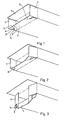
- FIGs. 1-5 are perspective views of one end of a box member according to the invention, illustrating successive phases of the closing of the box end.
- the box member shown is a cardboard member, which from a relevant carton factory is supplied as a flat tube member, which is erectable to the rectangular tubular shape as shown in Fig. 1.
- the open end of the box has two opposite side flaps 2, a lower closing flap 4 ("third flap"), and an upper closing flap 6 ("fourth flap”).
- the corner lines between the flap 6 and the two side flaps 2 are cut up, while the lower flap 4 is connected integrally with the two side flaps 2 through transverse strip portions 8.
- the non-illustrated opposite end of the box may be designed in a fully similar manner, though this will of course not be necessary in any way; thus, the other end of the box member may be provided with a so-called self-erecting end closure, which is automatically actuated to close the box end already by the erection of the flat starting member into its rectangular tubular shape.
- the said strip portions 8 each constitutes a rudiment of a triangular outer area of the lower flap 4 as defined by an oblique folding line a between the portions 4 and 8, this line being directed towards the root corner between the flaps 4 and 2.
- the folding line a starting from the outer edge of the flap 4, continues inwardly into a transverse slot portion 10 as constituting one leg of an angular slot, the other leg portion 12 of which stretches inwardly along the corner line between the flaps 4 and 2, whereby the slot portions 10 assist in confining the strip portions 8.
- the angular slot 10,12 leaves an outwardly projecting triangular flap portion 14.
- the operator folds in the side flaps 2 by applying a finger pressure to the area just outside the strip portions 8.
- the folding lines a are pressed into the material from the outside thereof, such that by the pressing in of each side flap 2 the strip portions 8 will show a natural tendency to push the lower flap 4 downwardly, see Fig. 2.
- the associated downward pivoting of the flap 4 will continue until the side flaps 2 as shown in Fig. 3 have reached a position, in which the strip portions are oriented practically vertically downwardly.
- the operator may start closing or half- closing the other end as here described, whereby the side flaps will form an introduction stop for the article to be packed.
- Partly closed box members as shown in Fig. 4 may be fed to a buffer or feeding magazine for automatic transfer to a simple end closing apparatus, which will cause the lower flap 4 to be folded upwardly (Fig. 5), to apply a gluestuff to the underside of the upper closing flap 6, and to pivot the latter flap downwardly for adhesively fastening it to the flap 4 over the area shown in hatched lines in Fig. 5, whereafter the box is finished.
- the projecting triangular portions 14 at the opposed outer sides of the closing flap 4 will serve the purpose of contributing to an effective adherence of the outermost flap 6, such that the latter will be adhesively secured over its entire width.
- the areas 14 are laid flat against the flaps 2 by intermediate of but a single layer thickness, whereby - despite the folded corner areas - a neat, flat closing of the flaps will be achievable.
- the areas of double layer thickness, i.e. the areas along the strips 8, are located well spaced from the ends of the glued area, such that they are easily pressed slightly inwardly in the box when the outermost flap 6 is closed, i.e. the folding connections used will not affect the visual appearance of the closed box end.
- Boxes according to the invention may be produced just as cheap as conventional boxes having four disintegrated closing flaps, only with the use of a modified punching tool.
Landscapes
- Engineering & Computer Science (AREA)
- Mechanical Engineering (AREA)
- Cartons (AREA)
- Closing Of Containers (AREA)
- Wrapping Of Specific Fragile Articles (AREA)
- Control And Other Processes For Unpacking Of Materials (AREA)
- Basic Packing Technique (AREA)
- Making Paper Articles (AREA)
- Closures For Containers (AREA)
Claims (2)
- . 1. Kartonbehälter der Art, die aufrichtbar ist, um eine rechteckige Hülse zu bilden, die wenigstens an einem Ende vier in Längsrichtung der Hülse vorspringende Verschlussklappen aufweist, und zwar zwei sich gegenüberliegende Seitenklappen (2), eine dazwischen befindliche dritte Klappe (4) und eine dierser gegenüberliegende vierte Klappe (6), die beim Schliessen des Behälterendes durch Einwärtsfalten der vier Klappen die äusserste oder zuletzt gefaltete Klappe zu bilden vermag und, z.B. durch Leimauftrag, an der Aussenseite der genannten dritten Klappe befestigt ist, dadurch gekennzeichnet, dass die zwei Seitenklappen (2) mit der dritten Klappe (4) über einen äusseren Teil ihrer gemeinsamen Kante verbunden sind, während der innere Teil (12) dieser Kante aufgeschnitten ist, wobei die Schneidlinie sich von ihrem äusseren Ende nach innen (10) über die dritte Klappe fortsetzt bis zu einer geneigten Faltlinie (a), die sich in der äusseren Endfläche der dritten Klappe längs einer Linie befindet, die gegen die jeweilige Ecke zwischen den Ansätzen der zwei benachbarten Klappen (4, 2) im Winkel von 45° zur Längsrichtung der dritten Klappe (4) gerichtet ist.
- 2. Behälter nach Anspruch 1, dadurch gekennzeichnet, dass die Schneidlinie (10, 12) als ein eckiger Schlitz ausgebildet ist, der einen flach vorspringenden Eckteil (14) an der dritten Klappe (4) belässt.
Priority Applications (1)
| Application Number | Priority Date | Filing Date | Title |
|---|---|---|---|
| AT85201473T ATE49550T1 (de) | 1984-09-14 | 1985-09-13 | Kartonbehaelter mit verschlussklappen fuer einen halbautomatischen verschluss. |
Applications Claiming Priority (2)
| Application Number | Priority Date | Filing Date | Title |
|---|---|---|---|
| DK4382/84 | 1984-09-14 | ||
| DK438284A DK150737C (da) | 1984-09-14 | 1984-09-14 | Kartonemballage med lukkeflige til halvautomatisk lukning |
Publications (3)
| Publication Number | Publication Date |
|---|---|
| EP0178702A2 EP0178702A2 (de) | 1986-04-23 |
| EP0178702A3 EP0178702A3 (en) | 1987-10-21 |
| EP0178702B1 true EP0178702B1 (de) | 1990-01-17 |
Family
ID=8133034
Family Applications (1)
| Application Number | Title | Priority Date | Filing Date |
|---|---|---|---|
| EP85201473A Expired - Lifetime EP0178702B1 (de) | 1984-09-14 | 1985-09-13 | Kartonbehälter mit Verschlussklappen für einen halbautomatischen Verschluss |
Country Status (5)
| Country | Link |
|---|---|
| EP (1) | EP0178702B1 (de) |
| AT (1) | ATE49550T1 (de) |
| DE (1) | DE3575400D1 (de) |
| DK (1) | DK150737C (de) |
| NO (1) | NO165909C (de) |
Families Citing this family (1)
| Publication number | Priority date | Publication date | Assignee | Title |
|---|---|---|---|---|
| US5292059A (en) * | 1993-03-18 | 1994-03-08 | The Mead Corporation | Tubular carton having triangular corner panels |
Family Cites Families (1)
| Publication number | Priority date | Publication date | Assignee | Title |
|---|---|---|---|---|
| US3529763A (en) * | 1968-10-17 | 1970-09-22 | Westvaco Corp | Self-locking canister or box |
-
1984
- 1984-09-14 DK DK438284A patent/DK150737C/da not_active IP Right Cessation
-
1985
- 1985-09-12 NO NO853577A patent/NO165909C/no unknown
- 1985-09-13 AT AT85201473T patent/ATE49550T1/de not_active IP Right Cessation
- 1985-09-13 DE DE8585201473T patent/DE3575400D1/de not_active Expired - Fee Related
- 1985-09-13 EP EP85201473A patent/EP0178702B1/de not_active Expired - Lifetime
Also Published As
| Publication number | Publication date |
|---|---|
| NO853577L (no) | 1986-03-17 |
| EP0178702A2 (de) | 1986-04-23 |
| DK438284A (da) | 1986-03-15 |
| EP0178702A3 (en) | 1987-10-21 |
| DK150737B (da) | 1987-06-09 |
| DE3575400D1 (de) | 1990-02-22 |
| DK438284D0 (da) | 1984-09-14 |
| NO165909B (no) | 1991-01-21 |
| DK150737C (da) | 1988-02-01 |
| NO165909C (no) | 1991-05-02 |
| ATE49550T1 (de) | 1990-02-15 |
Similar Documents
| Publication | Publication Date | Title |
|---|---|---|
| US4602735A (en) | Dispensing carton | |
| US5054644A (en) | Box | |
| US2513079A (en) | Collapsible box | |
| ES294651Y (es) | Caja carton para bolsas de liquido con espita de vertido | |
| US4767051A (en) | Knockdown carton with pre-glued bottom | |
| US3175750A (en) | Carton with handle and pouring spout | |
| US4005814A (en) | Carton with integral overwrap | |
| US4032060A (en) | Carton with self-sealing reclosable end closure | |
| US4101022A (en) | Recessed end container | |
| US2332250A (en) | Carton | |
| US3040961A (en) | Display carton | |
| US2048729A (en) | Carton and method | |
| US2532808A (en) | Foldable tray blank and tray | |
| US4066207A (en) | Dispenser carton boxes | |
| EP0178702B1 (de) | Kartonbehälter mit Verschlussklappen für einen halbautomatischen Verschluss | |
| US3049281A (en) | Flap seal box | |
| US2536948A (en) | Carton | |
| US2637483A (en) | Folded blank box | |
| US2317223A (en) | End flap construction for cardboard containers | |
| GB1202565A (en) | Container bottom closure | |
| US4233888A (en) | Method of making a collapsible drum-type container | |
| US3432086A (en) | Carton | |
| US3951330A (en) | Carton top closure arrangement | |
| US4411383A (en) | Carton and integral handle therefor | |
| US2708065A (en) | Collapsible carton |
Legal Events
| Date | Code | Title | Description |
|---|---|---|---|
| PUAI | Public reference made under article 153(3) epc to a published international application that has entered the european phase |
Free format text: ORIGINAL CODE: 0009012 |
|
| AK | Designated contracting states |
Kind code of ref document: A2 Designated state(s): AT BE CH DE FR GB IT LI NL SE |
|
| PUAL | Search report despatched |
Free format text: ORIGINAL CODE: 0009013 |
|
| AK | Designated contracting states |
Kind code of ref document: A3 Designated state(s): AT BE CH DE FR GB IT LI NL SE |
|
| 17P | Request for examination filed |
Effective date: 19880419 |
|
| 17Q | First examination report despatched |
Effective date: 19880912 |
|
| GRAA | (expected) grant |
Free format text: ORIGINAL CODE: 0009210 |
|
| AK | Designated contracting states |
Kind code of ref document: B1 Designated state(s): AT BE CH DE FR GB IT LI NL SE |
|
| PG25 | Lapsed in a contracting state [announced via postgrant information from national office to epo] |
Ref country code: LI Effective date: 19900117 Ref country code: IT Free format text: LAPSE BECAUSE OF FAILURE TO SUBMIT A TRANSLATION OF THE DESCRIPTION OR TO PAY THE FEE WITHIN THE PRESCRIBED TIME-LIMIT;WARNING: LAPSES OF ITALIAN PATENTS WITH EFFECTIVE DATE BEFORE 2007 MAY HAVE OCCURRED AT ANY TIME BEFORE 2007. THE CORRECT EFFECTIVE DATE MAY BE DIFFERENT FROM THE ONE RECORDED. Effective date: 19900117 Ref country code: FR Effective date: 19900117 Ref country code: CH Effective date: 19900117 Ref country code: AT Effective date: 19900117 |
|
| REF | Corresponds to: |
Ref document number: 49550 Country of ref document: AT Date of ref document: 19900215 Kind code of ref document: T |
|
| REF | Corresponds to: |
Ref document number: 3575400 Country of ref document: DE Date of ref document: 19900222 |
|
| REG | Reference to a national code |
Ref country code: CH Ref legal event code: PL |
|
| EN | Fr: translation not filed | ||
| PLBE | No opposition filed within time limit |
Free format text: ORIGINAL CODE: 0009261 |
|
| STAA | Information on the status of an ep patent application or granted ep patent |
Free format text: STATUS: NO OPPOSITION FILED WITHIN TIME LIMIT |
|
| 26N | No opposition filed | ||
| EAL | Se: european patent in force in sweden |
Ref document number: 85201473.7 |
|
| PGFP | Annual fee paid to national office [announced via postgrant information from national office to epo] |
Ref country code: DE Payment date: 19971121 Year of fee payment: 13 |
|
| PGFP | Annual fee paid to national office [announced via postgrant information from national office to epo] |
Ref country code: SE Payment date: 19980810 Year of fee payment: 14 |
|
| PGFP | Annual fee paid to national office [announced via postgrant information from national office to epo] |
Ref country code: GB Payment date: 19980907 Year of fee payment: 14 |
|
| PGFP | Annual fee paid to national office [announced via postgrant information from national office to epo] |
Ref country code: NL Payment date: 19980930 Year of fee payment: 14 |
|
| PGFP | Annual fee paid to national office [announced via postgrant information from national office to epo] |
Ref country code: BE Payment date: 19981016 Year of fee payment: 14 |
|
| PG25 | Lapsed in a contracting state [announced via postgrant information from national office to epo] |
Ref country code: DE Free format text: LAPSE BECAUSE OF NON-PAYMENT OF DUE FEES Effective date: 19990701 |
|
| PG25 | Lapsed in a contracting state [announced via postgrant information from national office to epo] |
Ref country code: GB Free format text: LAPSE BECAUSE OF NON-PAYMENT OF DUE FEES Effective date: 19990913 |
|
| PG25 | Lapsed in a contracting state [announced via postgrant information from national office to epo] |
Ref country code: SE Free format text: THE PATENT HAS BEEN ANNULLED BY A DECISION OF A NATIONAL AUTHORITY Effective date: 19990929 |
|
| PG25 | Lapsed in a contracting state [announced via postgrant information from national office to epo] |
Ref country code: BE Free format text: LAPSE BECAUSE OF NON-PAYMENT OF DUE FEES Effective date: 19990930 |
|
| BERE | Be: lapsed |
Owner name: SCHUR ENGINEERING A/S Effective date: 19990930 |
|
| PG25 | Lapsed in a contracting state [announced via postgrant information from national office to epo] |
Ref country code: NL Free format text: LAPSE BECAUSE OF NON-PAYMENT OF DUE FEES Effective date: 20000401 |
|
| GBPC | Gb: european patent ceased through non-payment of renewal fee |
Effective date: 19990913 |
|
| EUG | Se: european patent has lapsed |
Ref document number: 85201473.7 |
|
| NLV4 | Nl: lapsed or anulled due to non-payment of the annual fee |
Effective date: 20000401 |