EP0177709A1 - Seal and locking device - Google Patents
Seal and locking device Download PDFInfo
- Publication number
- EP0177709A1 EP0177709A1 EP85110063A EP85110063A EP0177709A1 EP 0177709 A1 EP0177709 A1 EP 0177709A1 EP 85110063 A EP85110063 A EP 85110063A EP 85110063 A EP85110063 A EP 85110063A EP 0177709 A1 EP0177709 A1 EP 0177709A1
- Authority
- EP
- European Patent Office
- Prior art keywords
- sealing
- sealing ring
- locking washer
- elastomer
- securing device
- Prior art date
- Legal status (The legal status is an assumption and is not a legal conclusion. Google has not performed a legal analysis and makes no representation as to the accuracy of the status listed.)
- Ceased
Links
- 238000007789 sealing Methods 0.000 claims abstract description 141
- 239000000806 elastomer Substances 0.000 claims abstract description 37
- 229920001971 elastomer Polymers 0.000 claims abstract description 37
- 239000004033 plastic Substances 0.000 claims description 18
- 229910052751 metal Inorganic materials 0.000 claims description 8
- 239000002184 metal Substances 0.000 claims description 8
- 239000000463 material Substances 0.000 claims description 6
- 230000002093 peripheral effect Effects 0.000 claims description 4
- 239000004952 Polyamide Substances 0.000 claims description 3
- 229920002647 polyamide Polymers 0.000 claims description 3
- 238000003825 pressing Methods 0.000 claims description 3
- CWYNVVGOOAEACU-UHFFFAOYSA-N Fe2+ Chemical compound [Fe+2] CWYNVVGOOAEACU-UHFFFAOYSA-N 0.000 claims description 2
- 238000005266 casting Methods 0.000 claims description 2
- 238000004049 embossing Methods 0.000 claims description 2
- 238000001746 injection moulding Methods 0.000 claims description 2
- 239000007769 metal material Substances 0.000 claims description 2
- 238000007788 roughening Methods 0.000 claims description 2
- 239000000126 substance Substances 0.000 claims description 2
- 229910000838 Al alloy Inorganic materials 0.000 claims 1
- 238000004519 manufacturing process Methods 0.000 description 8
- 238000003780 insertion Methods 0.000 description 3
- 230000037431 insertion Effects 0.000 description 3
- 239000000853 adhesive Substances 0.000 description 2
- 230000001070 adhesive effect Effects 0.000 description 2
- 239000007789 gas Substances 0.000 description 2
- 239000007788 liquid Substances 0.000 description 2
- 238000004073 vulcanization Methods 0.000 description 2
- 229910001369 Brass Inorganic materials 0.000 description 1
- 239000006004 Quartz sand Substances 0.000 description 1
- VYPSYNLAJGMNEJ-UHFFFAOYSA-N Silicium dioxide Chemical compound O=[Si]=O VYPSYNLAJGMNEJ-UHFFFAOYSA-N 0.000 description 1
- 229910000831 Steel Inorganic materials 0.000 description 1
- 238000010306 acid treatment Methods 0.000 description 1
- 229910052782 aluminium Inorganic materials 0.000 description 1
- XAGFODPZIPBFFR-UHFFFAOYSA-N aluminium Chemical compound [Al] XAGFODPZIPBFFR-UHFFFAOYSA-N 0.000 description 1
- PNEYBMLMFCGWSK-UHFFFAOYSA-N aluminium oxide Inorganic materials [O-2].[O-2].[O-2].[Al+3].[Al+3] PNEYBMLMFCGWSK-UHFFFAOYSA-N 0.000 description 1
- 239000010951 brass Substances 0.000 description 1
- 239000011248 coating agent Substances 0.000 description 1
- 238000000576 coating method Methods 0.000 description 1
- 238000011161 development Methods 0.000 description 1
- 230000018109 developmental process Effects 0.000 description 1
- 239000013013 elastic material Substances 0.000 description 1
- 239000003822 epoxy resin Substances 0.000 description 1
- 239000000945 filler Substances 0.000 description 1
- 239000003365 glass fiber Substances 0.000 description 1
- 238000003754 machining Methods 0.000 description 1
- 238000000034 method Methods 0.000 description 1
- TWNQGVIAIRXVLR-UHFFFAOYSA-N oxo(oxoalumanyloxy)alumane Chemical compound O=[Al]O[Al]=O TWNQGVIAIRXVLR-UHFFFAOYSA-N 0.000 description 1
- 229920000647 polyepoxide Polymers 0.000 description 1
- 230000008439 repair process Effects 0.000 description 1
- 239000007787 solid Substances 0.000 description 1
- 239000000243 solution Substances 0.000 description 1
- 239000002904 solvent Substances 0.000 description 1
- 229910001220 stainless steel Inorganic materials 0.000 description 1
- 239000010935 stainless steel Substances 0.000 description 1
- 239000010959 steel Substances 0.000 description 1
- 238000003860 storage Methods 0.000 description 1
Images


Classifications
-
- F—MECHANICAL ENGINEERING; LIGHTING; HEATING; WEAPONS; BLASTING
- F16—ENGINEERING ELEMENTS AND UNITS; GENERAL MEASURES FOR PRODUCING AND MAINTAINING EFFECTIVE FUNCTIONING OF MACHINES OR INSTALLATIONS; THERMAL INSULATION IN GENERAL
- F16J—PISTONS; CYLINDERS; SEALINGS
- F16J15/00—Sealings
- F16J15/02—Sealings between relatively-stationary surfaces
- F16J15/06—Sealings between relatively-stationary surfaces with solid packing compressed between sealing surfaces
- F16J15/10—Sealings between relatively-stationary surfaces with solid packing compressed between sealing surfaces with non-metallic packing
- F16J15/12—Sealings between relatively-stationary surfaces with solid packing compressed between sealing surfaces with non-metallic packing with metal reinforcement or covering
- F16J15/121—Sealings between relatively-stationary surfaces with solid packing compressed between sealing surfaces with non-metallic packing with metal reinforcement or covering with metal reinforcement
- F16J15/127—Sealings between relatively-stationary surfaces with solid packing compressed between sealing surfaces with non-metallic packing with metal reinforcement or covering with metal reinforcement the reinforcement being a compression stopper
-
- F—MECHANICAL ENGINEERING; LIGHTING; HEATING; WEAPONS; BLASTING
- F16—ENGINEERING ELEMENTS AND UNITS; GENERAL MEASURES FOR PRODUCING AND MAINTAINING EFFECTIVE FUNCTIONING OF MACHINES OR INSTALLATIONS; THERMAL INSULATION IN GENERAL
- F16B—DEVICES FOR FASTENING OR SECURING CONSTRUCTIONAL ELEMENTS OR MACHINE PARTS TOGETHER, e.g. NAILS, BOLTS, CIRCLIPS, CLAMPS, CLIPS OR WEDGES; JOINTS OR JOINTING
- F16B39/00—Locking of screws, bolts or nuts
- F16B39/22—Locking of screws, bolts or nuts in which the locking takes place during screwing down or tightening
- F16B39/24—Locking of screws, bolts or nuts in which the locking takes place during screwing down or tightening by means of washers, spring washers, or resilient plates that lock against the object
-
- F—MECHANICAL ENGINEERING; LIGHTING; HEATING; WEAPONS; BLASTING
- F16—ENGINEERING ELEMENTS AND UNITS; GENERAL MEASURES FOR PRODUCING AND MAINTAINING EFFECTIVE FUNCTIONING OF MACHINES OR INSTALLATIONS; THERMAL INSULATION IN GENERAL
- F16B—DEVICES FOR FASTENING OR SECURING CONSTRUCTIONAL ELEMENTS OR MACHINE PARTS TOGETHER, e.g. NAILS, BOLTS, CIRCLIPS, CLAMPS, CLIPS OR WEDGES; JOINTS OR JOINTING
- F16B43/00—Washers or equivalent devices; Other devices for supporting bolt-heads or nuts
- F16B43/001—Washers or equivalent devices; Other devices for supporting bolt-heads or nuts for sealing or insulation
Definitions
- the invention relates to a sealing and securing device with the features of the preamble of claim 1.
- screw connections with which, for example, machine parts, such as housing parts or the like, are connected, often have to be sealed against the escape of gases or liquids.
- screw seals which consist of an elastic material which deforms when the screw connection is tightened and which seals against the flat surface of the screw head and opposite on the parallel counter surface of the machine part to be connected and thus seals against the escape of gases, liquids etc. forms.
- a sealing ring which can be designed, for example, as an O-ring with a circular cross section, is pressed against the surface to be screwed by pressing the screw head.
- screw connections secure against unintentional loosening.
- locking washers are used, which have a grid, such as teeth, notches or the like. Such locking washers, which are also pushed onto the screw shaft, are compressed when the screw head is tightened and deformed so far that a firm mechanical connection is created between the head of the screw and the counter surface.
- the object of the invention is to develop a sealing and securing device with the features of the preamble of claim 1 in such a way that with simple means a structurally uniform Bulk article cost-effective sealing element is achieved, which is easy to assemble with the saving of additional sealing ring grooves.
- the sealing washer 1 shown in the drawing has an inner sealing ring 2, which is enclosed by a locking washer 3.
- the sealing washer 1 is pushed onto the shaft 4 of a screw 5 which has a head 6. Opposite the head 6 there is a lower part 7, in the bore 8 of which the shaft 4 of the screw 5 is inserted.
- the shaft 4 can be screwed into a corresponding thread of the lower part 7 with a thread end (not shown here).
- the screw 5 is clamped just so far against the lower part 7 that the distance between the Sealing surface 9 of the head 6 and the surface 10 of the lower part 7 is equal to the thickness of the sealing ring 2 in the axial direction.
- the sealing ring 2 is thus in an unloaded state. If the screw 5 is clamped axially towards the lower part 7 by further tightening, the distance between the sealing surface 9 and the surface 10 is reduced, the elastic sealing ring 2 being compressed.
- the locking washer 3 has an upper catch 11 facing the sealing surface 9 and a parallel catch 12 facing the surface 10.
- the locking washer 3 has a circular inner circumference 13 and a likewise circular outer wall 14.
- the grids 11, 12 and the inner circumference 13 and the outer wall 14 are of essentially the same length and at right angles, so that the locking washer 3 has a largely square cross section.
- the locking washer 3 is dimensioned so that the outer peripheral surface 14 is in the same plane as the outer peripheral side 15 of the head 6 of the screw 5.
- the locking washer 3 can advantageously be made of a metallic material, for example steel, preferably stainless Stainless steel. However, it can also be expedient to manufacture the locking washer 3 from a non-ferrous metal, for example from aluminum or brass. Furthermore for a particularly cost-effective production, it may be expedient to manufacture the locking washer 3 from a solid plastic material, for example polyamide or the like, also reinforced with glass fibers or enriched with other fillers such as quartz sand, aluminum oxide, alumina hydrate.
- the locking washer 3 has a relatively high compressive strength, so that when the screw 5 is tightened a perfect securing system and spacing from the lower part 7 is ensured by the sealing surface 9 of the head 6 on the grid 11 of the locking washer 3 and the surface 10 of the lower part 7 on the lower grid 12 of the locking washer 3 fit tightly and frictionally, so that an unintentional loosening or loosening of the screw 5 cannot occur, but a perfect screw lock is also given in the event of vibrations and vibration stresses and at the same time ensures a perfect seal via the sealing ring 2 is.
- the elastic sealing ring 2 preferably consists of a rubber-like elastomer material.
- the hardness of the elastomer material is preferably about 40 to 90 Shore A.
- the sealing ring 2 is therefore considerably softer than the locking washer 3, which has a much greater hardness or compressive strength, in order to fulfill its sealing function between the screw 5 and the lower part, and also greater tightening torques to resist the screw 5 for proper spacing and securing against unintentional loosening between the sealing surface 9 and the surface 10.
- the sealing ring 2 has an annular inner wall 16 and also an annular outer periphery 17.
- the diameter of the elastic sealing ring 2 is dimensioned in the region of the inner wall 16 so that it closely surrounds the peripheral surface 18 of the shaft 4.
- the sealing washer 1 is thus captively supported on the shaft 4 of the screw 5 by self-retention. At the same time, this always ensures perfect self-centering of the sealing washer 1, so that no additional manipulations for aligning or centering the sealing washer 1 are required during
- the diameter of the outer periphery 17 of the sealing ring 2 is dimensioned such that it is substantially equal to the diameter in the region of the inner periphery 13 of the locking washer 3.
- the elastomer sealing ring 2 is fixedly connected (connected) to the locking washer 3 according to the invention.
- This attachment or connection of the sealing ring 2 to the locking washer 3 can advantageously be formed or reinforced by mechanical surface roughening or chemical surface dissolving by means of solvent or acid treatment of the outer periphery 17 of the elastomer sealing ring 2 and / or the inner periphery 13 of the locking washer 3. It may also be advantageous to connect the sealing ring 2 and the locking washer 3 to one another by means of an additional, preferably low-viscosity adhesive.
- epoxy resin adhesive can be used, whose permanent temperature resistance is over 150 ° C.
- the elastic sealing ring 2 which in the installed state is supported radially absolutely securely on the inside by the circumferential surface 18 of the shaft 4 and on the outside by the inner circumference 13 of the locking washer 3, has mutually opposite sealing parts 19, 20 which are approximately triangular in cross section and each have two inclined surfaces 21, 22.
- the two inclined surfaces 21, 22 are arranged at an angle of approximately 90 ° to one another.
- the angular tip in the joint area of the two inclined surfaces 2 1 , 22 is formed here as a sealing lip 23, which thus surrounds the shaft 4 of the screw 5 at a distance as a circular line and bears sealingly on the sealing surface 9 of the head 6 and opposite on the surface 10 of the lower part 7 .
- the inclined surface 21, which drops from the sealing lip 23 towards the outside toward the locking washer 3, is oriented such that it abuts the corner part 24 formed by the catch 11, 11 and the inner circumference 13 of the locking washer 3.
- the sloping surface 23 sloping inwards from the sealing lip 23 is made somewhat longer than the outer sloping surface 21, so that here the inner wall 16 of the sealing ring 2 is somewhat shorter in the axial direction than the outer circumference 17.
- the width of the sealing ring 2 between the inner wall 16 and the outer circumference 17 is approximately equal to the width of the locking washer 3 between the inner circumference 13 and the outer wall 14 in the present exemplary embodiment.
- the elastomer sealing ring 2 is designed such that the diameter is approximately half the width of the sealing ring 2 between its inner wall 16 and outer circumference 17 than the diameter in the region of the inner wall 16.
- the grid 11, 12 of the locking washer 3 directly adjoins the connection point on the outer circumference 17 of the elastomer sealing ring 2.
- the grid 11, 12, which is set back relative to the sealing part 19, 20, so that the sealing part 19, 20 of the sealing ring 2 projects beyond the plane of the locking washer 3, has elevations and depressions, which are called radial grooves, circular or spiral grooves or can also be designed as surface knurling or the like.
- the catch 11, 12 can be produced, for example, by embossing or pressing, while in the case of a lock washer 3 made of plastic, the catch 11, 12 can be made directly during the injection molding or casting by appropriate mold design.
- the sealing washer 1 ' is essentially like the previously described sealing washer 1 of FIG. 1 and 2, however, the locking washer 3 'consists of an inner metal plate 25, which is coated here with a plastic layer 26 on all sides.
- the grid 11, 12 is formed directly in the plastic layer 26.
- the elastomer sealing ring 2 ' is connected directly to the plastic layer 26 with its outer circumference 17 on the inner circumference 13 of the locking washer 3 '.
- the connection of the sealing ring 2 'to the locking washer 3' can preferably be carried out as vulcanization, so that an extremely intimate and firm bond is given.
- the plastic layer 26 can be made of polyamide, for example.
- the in the FIG. 5 and 6 illustrated embodiment is approximately like the embodiment of FIG. 1 and 2, but in this sealing washer 1 "the elastomer sealing ring 2" is approximately trapezoidal in cross section.
- the inner wall 16 ′′ is longer than the thickness of the locking washer 3 ′′ between the grids 11, 12 formed on both end faces.
- the sealing lip 23 is thus formed by the angular corner region of the inner wall 16 and the sloping surface 21 that slopes away to the outside.
- the diameter of the elastomer sealing ring 2 "in the present exemplary embodiment in the region of the circular sealing lip 23 is equal to the diameter in the region of the inner wall 16.
- the width between the outer wall 14 and the inner circumference 13 of the locking washer 3" here is approximately 2 1/2 times larger than that Width of the elastomer sealing ring 2 "between the outer circumference 17 and the inner wall 16.
- the elastomer sealing ring 2 "'of the sealing washer 1"' on the inner wall 16 centering lips 27, which are directed radially in the direction of the central axis.
- a total of three centering lips 27 are formed, which are formed on the inner wall 16 at regular pitch intervals at an angle of 120 ° to one another.
- a pitch circle recess 28 is formed in the 120 ° corner areas of the elastomer sealing ring 1 '' '.
- FIG. 8 also shows that the sealing part 19, 20 of the elastomer sealing ring 2 "'having the centering lips 27 has a facing surface 29. This facing surface 29 is offset in height parallel to the level of the catch 11, 12 of the locking washer 3"'.
- the sealing washers 1 to 1 "'according to the invention can preferably be used both in vacuum systems and in pressure systems, since the screw 5 can be tightened with great force, the flow of force via the locking washer 3 to 3"' between the head 6 and the Lower part 7 is added. Retightening the screw 5 is therefore not necessary.
- the sealing washer 1 Up to 1 '" can be pushed fully automatically onto screw 5 for cost-effective mass production due to their design by means of corresponding feed devices. Standard screws can be used to a large extent and no additional mechanical sealing surface machining, for example for the introduction of a receiving groove or the like, is required assembled condition can be checked from the outside without further ado whether the sealing washer 1 to 1 "'has not been forgotten.
- a major advantage is that the screw seal and screw locking is achieved by a single structural element, so that a considerable simplification is achieved in the assembly as well as in storage, etc. in the manufacture of a screw locking. In addition, errors during assembly are avoided because now only a single component has to be used.
- the sealing washer 1 to 1 '" can be used without restriction for detachable screw connections.
- this lock is needed disassembly.
- the locking washer 3 to 3 "' is made of plastic or a metal plate 25 with an art Material layer 26 and made of plastic grid 11, 12, there is the further advantage that screw connections can also be sealed and secured at the same time, which do not require such high contact pressure, because the desired securing toothing between the screw head and the counter surface with the appropriate plastic material also is already achieved at a relatively low contact pressure due to the low resistance to deformation.
- a coating of the metal plate 25 with the plastic layer 26 in turn has the advantage of simpler production, because the raster 11, 12 designed according to the invention can be produced directly in the plastic layer 26 immediately during its production without an additional operation.
- sealing washer 1 to 1 "' according to the invention is that when using a single component as a securing part and sealing part compared to known comparable solutions, overall structural height is saved considerably, since the arrangement according to the invention of the grid 11, 12 on the surface in comparison only a very small overall height is required for introducing a separate insertion technique, for example, with an inserted 0-ring.
Abstract
Description
Die Erfindung betrifft eine Dicht- und Sicherungseinrichtung mit den Merkmalen des Oberbegriffs des Anspruchs 1.The invention relates to a sealing and securing device with the features of the preamble of
Bekannte Schraubverbindungen, mit denen beispielsweise Maschinenteile, wie Gehäuseteile oder dergleichen, verbunden werden, müssen oftmals gegen ein Ausdringen von Gasen oder Flüssigkeiten abgedichtet werden. Hierzu sind Schraubendichtungen bekannt, die aus einem elastischen Werkstoff bestehen, der sich beim Anziehen der Schraubverbindung verformt und sich an der Planfläche des Schraubenkopfes und gegenüberliegend an der parallelen Gegenfläche des zu verbindenden Maschinenteiles dichtend anlegt und somit eine Dichtung gegen Austreten von Gasen, Flüssigkeiten usw. bildet. Bei diesen bekannten Dichtungen wird also ein Dichtungsring, der zum Beispiel als im Querschnitt kreisringförmiger 0-Ring ausgeführt sein kann, durch Anpressen des Schraubenkopfes gegen die zu verschraubende Fläche gedrückt. Dazu ist es bekannt, Schraubenverbindungen gegen ein unbeabsichtigtes Lösen zu sichern. Hierzu dienen Sicherungsscheiben, die eine Rasterung, wie Zacken, Kerben oder dergleichen aufweisen. Solche Sicherungsscheiben, die ebenfalls auf den Schraubenschaft aufgeschoben werden, werden beim Anziehen des Schraubenkopfes zusammengedrückt und dabei so weit verformt, daß eine feste mechanische Verbindung zwischen dem Kopf der Schraube und der Gegenfläche entsteht.Known screw connections, with which, for example, machine parts, such as housing parts or the like, are connected, often have to be sealed against the escape of gases or liquids. For this purpose screw seals are known which consist of an elastic material which deforms when the screw connection is tightened and which seals against the flat surface of the screw head and opposite on the parallel counter surface of the machine part to be connected and thus seals against the escape of gases, liquids etc. forms. In the case of these known seals, a sealing ring, which can be designed, for example, as an O-ring with a circular cross section, is pressed against the surface to be screwed by pressing the screw head. For this it is known to use screw connections secure against unintentional loosening. For this purpose, locking washers are used, which have a grid, such as teeth, notches or the like. Such locking washers, which are also pushed onto the screw shaft, are compressed when the screw head is tightened and deformed so far that a firm mechanical connection is created between the head of the screw and the counter surface.
Die Schraubverbindungen waren dafür zumeist so ausgebildet, daß unterhalb der Sicherungsscheibe im Körper des anzuziehenden Maschinenteiles eine Nut eingestochen war, in die ein zur Abdichtung erforderlicher 0-Ring eingelegt wurde. Die Herstellung dieser bekannten Abdichtungs- und Sicherungselemente bei Schraubverbindungen ist außerordentlich aufwendig, da das Einbringen der Dichtringe in einem besonderen, relativ umständlichen, zeitaufwendigen und somit teueren Arbeitsvorgang vorgenommen werden muß. Außerdem besteht der funktionelle Nachteil, daß das Einlegen der getrennten Elemente, nämlich der Si-cherungsscheibe und des Dichtringes, insbesondere wenn der Dichtring in eine Nut einzulegen ist, bei der Montage, insbesondere bei Reparaturfällen, vergessen werden kann, so daß die unbedingt notwendige Dichtfunktion nicht gewährleistet ist.The screw connections were usually designed so that a groove was inserted under the locking washer in the body of the machine part to be tightened, into which a 0-ring required for sealing was inserted. The production of these known sealing and securing elements for screw connections is extremely complex, since the insertion of the sealing rings has to be carried out in a special, relatively cumbersome, time-consuming and thus expensive operation. There is also the functional disadvantage that the insertion of the separate elements, namely the locking washer and the sealing ring, especially when the sealing ring is to be inserted into a groove, can be forgotten during assembly, in particular in the case of repairs, so that the absolutely necessary sealing function is not guaranteed.
Die Aufgabe der Erfindung besteht darin, eine Dicht-und Sicherungseinrichtung mit den Merkmalen des Oberbegriffs des Anspruchs 1 dahingehend weiterzubilden, daß mit einfachen Mitteln ein baueinheitlich als Massenartikel kostengünstig herstellbares Dichtsicherungselement erzielt wird, das unter Einsparung zusätzlicher Dichtringaufnahmenuten einfach zu montieren ist.The object of the invention is to develop a sealing and securing device with the features of the preamble of
Diese Aufgabe wird erfindungsgemäß durch die kennzeichnenden Merkmale des Anspruchs 1 gelöst.This object is achieved by the characterizing features of
Bevorzugte Ausgestaltungen und Weiterbildungen sowie weitere Vorteile und wesentliche Einzelheiten der Erfindung sind den Merkmalen der Unteransprüche, der nachfolgenden Beschreibung und der Zeichnung zu entnehmen, die in schematischer Darstellung bevorzugte Ausführungsformen als Beispiel zeigt. Es stellen dar:
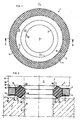
- FIG. 1 eine Draufsicht auf eine erfindungsgemäße Dichtsicherungsscheibe,
- FIG. 2 eine geschnittene Seitenansicht der Dichtsicherungsscheibe gemäß dem Schnitt II-II der FIG. 1 mit einem gestrichelt angedeuteten Unterteil, in das eine ebenfalls gestrichelt dargestellte Schraube, welche die Dichtsicherungsscheibe durchsetzt, eingebracht ist,
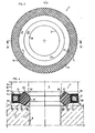
- FIG. 3 eine Draufsicht auf eine zweite Ausführungsform einer erfindungsgemäßen Dichtsicherungsscheibe ähnlich der FIG. 1,
- FIG. 4 eine geschnittene Seitenansicht der Dichtsicherungsscheibe gemäß dem Schnitt IV-IV der FIG. 3,
- FIG. 5 eine Draufsicht auf eine dritte Ausführungsform einer erfindungsgemäßen Dichtsicherungsscheibe,
- FIG. 6 eine geschnittene Seitenansicht der Dichtsicherungsscheibe gemäß dem Schnitt VI-VI der FIG. 5,
- FIG. 7 eine Draufsicht auf eine vierte Ausführungsform einer erfindungsgemäßen Dichtsicherungsscheibe und
- FIG. 8 eine geschnittene Seitenansicht der Dichtsicherungsscheibe gemäß dem Schnitt VIII-VIII der FIG. 7.
- FIG. 1 shows a plan view of a sealing washer according to the invention,
- FIG. 2 is a sectional side view of the sealing washer according to section II-II of FIG. 1 with a lower part indicated by dashed lines, into which a screw, also shown in dashed lines, which penetrates the sealing washer, is introduced,
- FIG. 3 shows a plan view of a second embodiment of a sealing washer according to the invention similar to FIG. 1,
- FIG. 4 is a sectional side view of the sealing washer according to section IV-IV of FIG. 3,
- FIG. 5 shows a plan view of a third embodiment of a sealing washer according to the invention,
- FIG. 6 is a sectional side view of the sealing washer according to section VI-VI of FIG. 5,
- FIG. 7 shows a plan view of a fourth embodiment of a sealing washer according to the invention and
- FIG. 8 is a sectional side view of the sealing washer according to section VIII-VIII of FIG. 7.
Die in der Zeichnung dargestellte Dichtsicherungsscheibe 1 weist einen inneren Dichtring 2 auf, der von einer Sicherungsscheibe 3 umschlossen ist. Die Dichtsicherungsscheibe 1 ist auf den Schaft 4 einer Schraube 5 aufgeschoben, die einen Kopf 6 besitzt. Gegenüber dem Kopf 6 befindet sich ein Unterteil 7, in dessen Bohrung 8 der Schaft 4 der Schraube 5 eingesetzt ist. Der Schaft 4 kann mit einem hier nicht dargestellten Gewindeende in ein entsprechendes Gewinde des Unterteiles 7 eingeschraubt sein. Es ist jedoch auch möglich, die Schraube 5 mit einer hier nicht dargestellten Gewindemutter in axialer Richtung gegen den Unterteil 7 zu verspannen.The sealing
Bei dem in der FIG. 2 dargestellten Ausführungsbeispiel ist die Schraube 5 gerade so weit gegen den Unterteil 7 verspannt, daß der Abstand zwischen der Dichtfläche 9 des Kopfes 6 und der Oberfläche 10 des Unterteils 7 gleich der Dicke des Dichtringes 2 in axialer Richtung ist. Der Dichtring 2 befindet sich hier somit in einem unbelastetem Zustand. Wird die Schraube 5 durch weiteres Anziehen axial in Richtung gegen den Unterteil 7 verspannt, so verringert sich der Abstand zwischen der Dichtfläche 9 und der Oberfläche 10, wobei der elastische Dichtring 2 zusammengedrückt wird.In the in the FIG. 2 embodiment shown, the
Die Sicherungsscheibe 3 besitzt eine der Dichtfläche 9 zugewandte obere Rasterung 11 und gegenüberliegend eine der Oberfläche 10 zugewandte parallele Rasterung 12. Außerdem weist die Sicherungsscheibe 3 einen kreisrunden Innenumfang 13 und eine ebenfalls kreisrunde Außenwand 14 auf. Beim vorliegenden Ausführungsbeispiel sind die Rasterungen 11,12 und der Innenumfang 13 sowie die Außenwand 14 im wesentlichen gleich lang und rechtwinklig ausgeführt, so daß die Sicherungsscheibe 3 einmweitgehend quadratischen Querschnitt besitzt.The
Die Sicherungsscheibe 3 ist in ihrem Durchmesser so bemessen, daß die äußere Umfangsfläche 14 in derselben Ebene sich befindet wie die äußere Umfangsseite 15 des Kopfes 6 der Schraube 5. Die Sicherungsscheibe 3 kann vorteilhaft aus einem metallischen Werkstoff, zum Beispiel aus Stahl, bevorzugt aus nichtrostendem Edelstahl, hergestellt sein. Es kann jedoch auch zweckmäßig sein, die Sicherungsscheibe 3 aus einem Nichteisenmetall, zum Beispiel aus Aluminium oder Messing, herzustellen. Darüber hinaus kann es für eine besonders kostengünstig Herstellung zweckmäßig sein, die Sicherungsscheibe 3 aus einem festen Kunststoffmaterial, zum Beispiel Polyamid oder dergleichen, anzufertigen, auch mit Glasfasern verstärkt oder mit anderweitigen Füllstoffen, wie.zum Beispiel Quarzsand, Aluminiumoxid, Tonerdehydrat, angereichert sein kann. Wichtig ist, daß die Sicherungsscheibe 3 eine verhältnismäßig hohe Druckfestigkeit aufweist, so daß beim Anziehen der Schraube 5 eine einwandfreie Sicherungsanlage und Abstandshaltung zum Unterteil 7 hin gewährleistet ist, indem die Dichtfläche 9 des Kopfes 6 an der Rasterung 11 der Sicherungsscheibe 3 und die Oberfläche 10 des Unterteils 7 an der unteren Rasterung 12 der Sicherungsscheibe 3 fest und reibschlüssig anliegen, so daß ein unbeabsichtigtes Lösen beziehungsweise Lockern der Schraube 5 nicht auftreten kann, sondern eine einwandfreie Schraubensicherung auch bei Vibrationen und Schwingungsbeanspruchungen gegeben und gleichzeitig eine einwandfreie Abdichtung über den Dichtring 2 gewährleistet ist.The
Der elastische Dichtring 2 besteht bevorzugt aus einem gummiartigen Elastomerwerkstoff. Die Härte des Elastomerwerkstoffes beträgt vorzugsweise etwa 40 bis 90 Shore A. Der Dichtring 2 ist somit zur Erfüllung seiner Dichtfunktion zwischen der Schraube 5 und dem Unterteil 7 erheblich weicher als die Sicherungsscheibe 3, die eine wesentlich größere Härte beziehungsweise Druckfestigkeit besitzt, um auch größeren Anzugsmomenten der Schraube 5 für eine einwandfreie Abstandshaltung und Sicherung gegen ein unbeabsichtiges Lösen zwischen der Dichtfläche 9 und der Oberfläche 10 zu widerstehen. Der Dichtring 2 weist eine kreisringförmige Innenwand 16 und einen ebenfalls kreisringförmigen Außenumfang 17 auf. Der Durchmesser des elastischen Dichtringes 2 ist im Bereich der Innenwand 16 so bemessen, daß diese die Umfangsfläche 18 des Schaftes 4 eng umschließt. Die.Dichtsicherungsscheibe 1 ist damit durch Selbsthaltung unverlierbar am Schaft 4 der Schraube 5 gelagert. Gleichzeitig ist dadurch stets eine einwandfreie Selbstzentrierung der Dichtsicherungsscheibe 1 gegeben, so daß bei der Montage keine zusätzlichen Manipulationen zur Ausrichtung beziehungsweise Zentrierung der Dichtsicherungsscheibe 1 erforderlich sind.The
Der Durchmesser des Außenumfangs 17 des Dichtringes 2 ist so bemessen, daß er im wesentlichen gleich dem Durchmesser im bereich des Innenumfangs 13 der Sicherungsscheibe 3 ist. Der Elastomerdichtring 2 ist mit der Sicherungsscheibe 3 erfindungsgemäß fest verbunden (angebunden). Diese Befestigung beziehungsweise Anbindung des Dichtringes 2 an der Sicherungsscheibe 3 kann vorteilhaft durch eine mechanische Oberflächenaufrauhung oder chemische Oberflächenanlösung mittels Lösungsmittel oder Säurebehandlung des Außenumfangs 17 des Elastomerdichtrings 2 und/oder des Innenumfangs 13 der Sicherungsscheibe 3 mitgebildet beziehungsweise verstärkt sein. Es kann auch günstig sein, den Dichtring 2 und die Sicherungsscheibe 3 mittels eines zusätzlichen,vorzugsweise dünnflüssigen Klebstoffs miteinander zu verbinden. Für hochwertige Anwendungen kann dazu zum Beispiel Epoxidharzkleber verwendet werden, dessen Dauertemperaturbeständigkeit über 150°C beträgt. Der elastische Dichtring 2, der im eingebauten Zustand innen von der Umfangsfläche 18 des Schaftes 4 und außen vom Innenumfang 13 der Sicherungsscheibe 3 radial absolut sicher abgestützt ist, weist stirnseitig einander gegenüberliegende Dichtungsteile 19, 20 auf, die im.Querschnitt etwa dreieckförmig gestaltet sind und je zwei Schrägflächen 21,22 besitzen. Die beiden Schrägflächen 21,22 sind in einem Winkel von etwa 90° zueinander angeordnet. Die Winkelspitze im Stoßbereich der beiden Schrägflächen 21,22 ist hier als Dichtlippe 23 ausgebildet, die somit als Kreislinie den Schaft 4 der Schraube 5 auf Abstand umringt und an der Dichtfläche 9 des Kopfes 6 sowie gegenüberliegend an der Oberfläche 10 des Unterteils 7 dichtend anliegt.The diameter of the
Die Schrägfläche 21, die von der Dichtlippe 23 in Richtung nach außen zur Sicherungsscheibe 3 hin abfällt, ist so ausgerichtet, daß sie an den von der Rasterung 11,12 und von dem Innenumfang 13 der Sicherungsscheibe 3 gebildeten Eckteil 24 angrenzt. Die von der Dichtlippe 23 nach innen abfallende Schrägfläche 23 ist etwas länger als die äußere Schrägfläche 21 ausgeführt, so daß hier in axialer Richtung die Innenwand 16 des Dichtringes 2 etwas kürzer ist als der Außenumfang 17.The
Außerdem ist der FIG. 2 zu entnehmen, daß beim vorliegenden Ausführungsbeispiel die Breite des Dichtringes 2 zwischen der Innenwand 16 und dem Außenumfang 17 in etwa gleich der Breite der Sicherungsscheibe 3 zwischen dem Innenumfang 13 und der Außenwand 14 ist. Im Bereich der kreislinienförmigen Dichtlippe 23 ist der Elastomerdichtring 2 so ausgeführt, daß der Durchmesser etwa um die Hälfte der Breite des Dichtringes 2 zwischen dessen Innenwand 16 und Außenumfang 17 größer ist als der Durchmesser im Bereich der Innenwand 16.In addition, the FIG. 2 that the width of the
Die Rasterung 11,12 der Sicherungsscheibe 3 grenzt unmittelbar an die Verbindungsstelle am Außenumfang 17 des Elastomerdichtringes 2 an. Die Rasterung 11,12, die gegenüber dem Dichtungsteil 19,20 zurückgesetzt ist, so daß der Dichtungsteil 19,20 des Dichtringes 2 die Ebene der Sicherungsscheibe 3 überragt, weist Erhöhungen und Vertiefungen auf, die als radiale Riefen, kreisring- oder spiralförmige Rillen oder auch als Oberflächenrändelung oder dergleichen ausgebildet sein können. Bei einer aus Metall bestehenden Sicherungsscheibe 3 kann die Rasterung 11,12 zum Beispiel durch Prägen oder Pressen hergestellt werden, während bei einer aus Kunststoff hergestellten Sicherungsscheibe 3 die Rasterung 11,12 gleich während des Formspritzens oder Formgießens durch entsprechende Werkzeugformgestaltung angefertigt werden kann.The
Bei dem in den FIG. 3 und 4 dargestellten Ausführungsbeispiel ist die Dichtsicherungsscheibe 1' im wesentlichen wie die zuvor beschriebene Dichtsicherungsscheibe 1 der FIG. 1 und 2 ausgeführt, jedoch besteht die Sicherungsscheibe 3' aus einer inneren Metallplatine 25, die hier mit einer Kunststoffschicht 26 allseits umhüllt ist. Die Rasterung 11,12 ist bei dieser Ausführungsform unmittelbar in der Kunststoffschicht 26 ausgebildet. Der Elastomerdichtring 2' ist mit seinem Außenumfang 17 am Innenumfang 13 der Sicherungsscheibe 3' unmittelbar mit der Kunststoffschicht 26 verbunden. Die Verbindung des Dichtringes 2' mit der Sicherungsscheibe 3' kann bevorzugt als Vulkanisation ausgeführt sein, so daß ein äußerst inniger und fester Verbund gegeben ist. Die Kunststoffschicht 26 kann zum Beispiel aus Polyamid bestehen. Bei dem eingangs beschriebenen Ausführungsbeispiel der FIG. 1 und 2 ist es auch möglich, den Dichtring 2 mit der Sicherungsscheibe 3 unmittelbar durch Vulkanisation zu verbinden, wenn die Sicherungsscheibe 3 aus Kunststoff hergestellt ist.In the in the FIG. 3 and 4 shown embodiment, the sealing washer 1 'is essentially like the previously described sealing
Das in den FIG. 5 und 6 dargestellte Ausführungsbeispiel ist in etwa wie das eingangs beschriebene Ausführungsbeispiel der FIG. 1 und 2 ausgeführt, doch ist bei dieser Dichtsicherungsscheibe 1" der Elastomerdichtring 2" im Querschnitt etwa trapezförmig ausgebildet. Die Innenwand 16" ist länger als die Dicke der Sicherungsscheibe 3" zwischen den an beiden Stirnseiten ausgebildeten Rasterungen 11,12. Die Dichtlippe 23 wird hierbei somit durch den Winkeleckbereich der Innenwand 16 und der nach außen abfallenden Schrägfläche 21 gebildet. Der Durchmesser des Elastomerdichtringes 2" ist beim vorliegenden Ausführungsbeispiel im Bereich der kreislinienförmigen Dichtlippe 23 gleich dem Durchmesser im Bereich der Innenwand 16. Die Breite zwischen der Außenwand 14 und dem Innenumfang 13 der Sicherungsscheibe 3" ist hier etwa 2 1/2 mal größer als die Breite des Elastomerdichtringes 2" zwischen dem Außenumfang 17 und der Innenwand 16.The in the FIG. 5 and 6 illustrated embodiment is approximately like the embodiment of FIG. 1 and 2, but in this
Bei dem in den FIG. 7 und 8 dargestellten Ausführungsbeispiel weist der Elastomerdichtring 2"' der Dichtsicherungsscheibe 1"' an der Innenwand 16 Zentrierlippen 27 auf, die radial in Richtung zur Mittenachse gerichtet sind. Hierbei sind insgesamt drei Zentrierlippen'27 ausgebildet, die in gleichmäßigen Teilkreisabständen in einem Winkel von 120° zueinander an der Innenwand 16 ausgebildet sind. Zwischen je zwei Zentrierlippen 27 der Innenwand 16 ist in den 120°-Winkeleckbereichen des Elastomerdichtringes 1''' je eine Teilkreisausnehmung 28 ausgebildet. Wenn die Dichtsicherungsscheibe 1'" auf den Schaft 4 einer Schraube 5 aufgeschoben wird, grenzen die Zentrierlippen 27 mit ihrem Längsmittenbereich tangential an die Umfangsfläche 18 des Schaftes 4 an, so daß die Dichtsicherungsscheibe 1"' praktisch in Form einer Dreipunktzentrierung am Schaft 4 ausgerichtet und gehalten ist. Die FIG. 8 zeigt zudem, daß der Dichtungsteil 19,20 des die Zentrierlippen 27 aufweisenden Elastomerdichtringes 2"' eine Plandichtfläche 29 besitzt. Diese Plandichtfläche 29 liegt höhenversetzt parallel zur Ebene der Rasterung 11,12 der Sicherungsscheibe 3"'.In the in the FIG. 7 and 8 illustrated embodiment, the
Die erfindungsgemäßen Dichtsicherungsscheiben 1 bis 1"' können bevorzugt sowohl bei Vakuum-aLs auch bei Drucksystemen angewandt werden, da die Schraube 5 mit großer Kraft fest angezogen werden kann, wobei der Kraftfluß über die Sicherungsscheibe 3 bis 3"' zwischen dem Kopf 6 und dem Unterteil 7 aufgenommen wird. Ein Nachziehen der Schraube 5 ist deshalb nicht erforderlich. Die Dichtsicherungsscheibe 1 bis 1'" kann für eine kostengünstige Massenproduktion aufgrund ihrer Gestaltung über entsprechende Zuführeinrichtungen vollautomatisch auf die Schraube 5 aufgeschoben werden. Es können weitgehend handelsübliche Schrauben eingesetzt werden und es sind keine zusätzlichen maschinellen Dichtflächenbearbeitungen, zum Beispiel für die Einbringung einer Aufnahmenut oder dergleichen erforderlich. Im montierten Zustand kann nachträglich von außen ohne weiteres kontrolliert werden, ob die Dichtsicherungsscheibe 1 bis 1"' nicht vergessen worden ist.The sealing
Ein wesentlicher Vorteil besteht darin, daß die Schraubenabdichtung und Schraubensicherung durch ein einziges baueinheitliches Element erreicht wird, so daß bei der Herstellung einer Schraubensicherung eine erhebliche Vereinfachung sowohl bei der Montage als auch bei der Lagerhaltung usw. erzielt wird. Darüber hinaus sind Fehler bei der Montage vermieden, weil nunmehr nur noch ein einziges Bauteil einzusetzen ist.A major advantage is that the screw seal and screw locking is achieved by a single structural element, so that a considerable simplification is achieved in the assembly as well as in storage, etc. in the manufacture of a screw locking. In addition, errors during assembly are avoided because now only a single component has to be used.
Ein weiterer wesentlicher Vorteil besteht darin, daß die Dichtsicherungsscheibe 1 bis 1'" bei lösbaren Schraubenverbindungen uneingeschränkt verwendet werden kann. Im Gegensatz zu anderen Schraubensicherungen, die beispielsweise auf chemischem Wege eine absolute Formschlußverbindung zwischen dem Schraubenkopf und dem zu verbindenden Maschinenteil herstellen, brauchtdiese Sicherung bei einer Demontage nicht zerstört zu werden. Sofern die Sicherungsscheibe 3 bis 3"' aus Kunststoff besteht oder aus einer Metallplatine 25 mit einer Kunststoffschicht 26 und aus Kunststoff bestehender Rasterung 11,12 hergestellt ist, ist der weitere Vorteil gegeben, daß auch Schraubenverbindungen abgedichtet und zugleich gesichert werden können, die keinen so hohen Anpreßdruck erfordern, weil die erwünschte Sicherungsverzahnung zwischen dem Schraubenkopf und der Gegenfläche bei entsprechendem Kunststoffmaterial auch schon bei einem verhältnismäßig niedrigen Anpreßdruck infolge des geringen Verformungswiderstandes erreicht wird.Another important advantage is that the sealing
Eine Beschichtung der Metallplatine 25 mit der Kunststoffschicht 26 hat wiederum den Vorteil einer einfacheren Herstellung, weil die erfindungsgemäß ausgebildete Rasterung 11,12 unmittelbar in der Kunststoffschicht 26 sofort bei deren Herstellung ohne zusätzlichen Arbeitsgang angefertigt werden kann.A coating of the
Ein weiterer wesentlicher Vorteil der erfindungsgemäßen Dichtsicherungsscheibe 1 bis 1"' besteht darin, daß bei Verwendung eines einzigen Bauteils als Sicherungsteil und Abdichtteil gegenüber bekannten vergleichbaren Lösungen erheblich an Bauhöhe insgesamt eingespart wird, da die erfindungsgemäße Anordnung der Rasterung 11,12 an der Oberfläche im Vergleich zum Einbringen einer beispielsweise getrennten Einstechnut mit eingelegtem 0-Ring nur eine sehr geringe Bauhöhe erfordert.Another significant advantage of the sealing
Claims (15)
dadurch gekennzeichnet, daß die Anbindung des Elastomerdichtringes (2 bis 2"') an der Sicherungsscheibe (3 bis 3"') durch eine mechanische Oberflächenaufrauhung oder chemische Oberflächenanlösung des Außenumfanges (17) des Elastomerdichtrings (2 bis 2"') und/oder des Innenumfanges (13) der Sicherungsscheibe (3 bis 3"') mitgebildet ist, wobei vorzugsweise der Elastomerdichtring (2 bis 2"') am Kunststoff der Sicherungsscheibe (3 bis 3"') bevorzugt anvulkanisiert ist.5. Sealing and securing device according to one of claims 1 to 4,
characterized in that the connection of the elastomer sealing ring (2 to 2 "') to the locking washer (3 to 3"') by mechanical surface roughening or chemical surface dissolving of the outer circumference (17) of the elastomer sealing ring (2 to 2 "') and / or the Inner circumference (13) of the locking washer (3 to 3 "') is formed, preferably the elastomer sealing ring (2 to 2"') on the plastic the locking washer (3 to 3 "') is preferably vulcanized.
dadurch gekennzeichnet, daß die Rasterung (11,12) mit den Erhöhungen und Vertiefungen in der Sicherungsscheibe (3 bis 3"') als radiale Riefen, kreisring-oder spiralförmige Rillen beziehungsweise Oberflächenrändelung ausgebildet und durch Prägen oder Pressen sowie durch Kunststoff-Formspritzen oder Kunststoff-Formgießen an der Stirnseite der Sicherungsscheibe (3 bis 3"') beziehungsweise in der Kunststoffschicht (26) der Metallplatine (25) ausgeführt sind, wobei vorzugsweise die Rasterung (11,12) unmittelbar an die Verbindung am Außenumfang (17) des Elastomerdichtringes (2 bis 2"') angrenzt.6. Sealing and securing device according to one of claims 1 to 5,
characterized in that the grid (11, 12) with the elevations and depressions in the locking washer (3 to 3 "') is designed as radial grooves, circular or spiral-shaped grooves or surface knurling and by embossing or pressing as well as by plastic injection molding or plastic - Mold casting on the end face of the locking washer (3 to 3 "') or in the plastic layer (26) of the metal plate (25), preferably with the catch (11, 12) directly on the connection on the outer circumference (17) of the elastomer sealing ring ( 2 to 2 "').
Ansprüche 1 bis 6,
dadurch gekennzeichnet, daß der mit der Sicherungsscheibe (3 bis 3"') verbundene Elastomerdichtring (2 bis 2"') mit einer Innenwand (16) den Schaft (4) der Schraube (5) an seiner Umfangsfläche (18) eng umschließt und zwischen dieser und dem Innenumfang (13) der Sicherungsscheibe (3 bis 3"') innen und außen radial gestützt ist.7. Sealing and securing device according to one of the
Claims 1 to 6,
characterized in that the elastomer sealing ring (2 to 2 "') connected to the locking washer (3 to 3"') closely encloses the shank (4) of the screw (5) on its circumferential surface (18) with an inner wall (16) and between this and the inner circumference (13) of the locking washer (3 to 3 "') are supported radially inside and outside.
Ansprüche 1 bis 7,
dadurch gekennzeichnet, daß der die Rasterung (11,12) der Sicherungsscheibe (3,3',3") überragende Dichtungsteil (19,20) des Elastomerdichtringes (2,2',2") im Querschnitt etwa dreieckförmig ausgebildet ist und eine kreislinienförmige Dichtlippe (23) mit einer zur Rasterung (11,12) hin geneigten Schrägfläche (21) aufweist, wobei vorzugsweise die kreislinienförmige Dichtlippe (23)im Stoßbereich zweier etwa in einem 90° Winkel zueinander angeordneter Schrägflächen (21,22) ausgebildet ist.8. Sealing and securing device according to one of the
Claims 1 to 7,
characterized in that the sealing part (19, 20) of the elastomer sealing ring (2, 2 ', 2 ") projecting beyond the catch (11, 12) of the locking washer (3, 3', 3") is approximately triangular in cross section and has a circular-shaped sealing lip (23) with an inclined surface (21) inclined towards the grid (11, 12), the circular-shaped sealing lip (23) preferably being formed in the joint region of two inclined surfaces (21, 22) arranged approximately at a 90 ° angle to one another is.
dadurch gekennzeichnet, daß der Durchmesser des Elastomerdichtringes (2, 2', 2") im Bereich der kreislinienförmigen Dichtlippe (23) etwa um die Hälfte der Breite des Elastomerdichtringes (2,2',2") zwischen dessen Innenwand (16) und dem Innenumfang (13) der Sicherungsscheibe (3,3',3") kleiner ist als im Bereich des Außenumfanges (17) und daß die Breite des Elastomerdichtrings (2,2') zwischen der Innenwand (16) und dem Außenumfang (17) etwa gleich der Breite der Sicherungsscheibe (3,3') zwischen dem Innenumfang (13) und der Außenwand (14) ist.9. Sealing and securing device according to one of claims 1 to 8,
characterized in that the diameter of the elastomer sealing ring (2, 2 ', 2 ") in the region of the circular sealing lip (23) about half the width of the elastomer sealing ring (2,2', 2") between the inner wall (16) and the Inner circumference (13) of the locking washer (3,3 ', 3 ") is smaller than in the area of the outer circumference (17) and that the width of the elastomer sealing ring (2,2') between the inner wall (16) and the outer circumference (17) is approximately is equal to the width of the locking washer (3,3 ') between the inner circumference (13) and the outer wall (14).
dadurch gekennzeichnet, daß in axialer Richtung die Innenwand (16) des Elastomerdichtringes (2,2') kürzer als die Dicke der im Querschnitt rechteckigen, vorzugsweise quadratischen Sicherungsscheibe (3,31) zwischen den an beiden Stirnseiten ausgebildeten Rasterungen (11,12) ist, und daß der Durchmesser des Elastomerdichtringes (2") im Bereich der kreislinienförmigen Dichtlippe (23) gleich dem Durchmesser der Innenwand (16) ist (Fig. 5 und 6).10. Sealing and securing device according to one of claims 1 to 9,
characterized in that, in the axial direction, the inner wall (16) of the elastomer sealing ring (2,2 ') is shorter than the thickness of the preferably square, preferably square locking washer (3,3 1 ) between the catches (11, 12) formed on both end faces and that the diameter of the elastomer sealing ring (2 ") in the region of the circular sealing lip (23) is equal to the diameter of the inner wall (16) (FIGS. 5 and 6).
dadurch gekennzeichnet, daß der Elastomerdichtring (2'') im Querschnitt etwa trapezförmig ist und daß in axialer Richtung die Innenwand (16) länger als die Dicke der Sicherungsscheibe (3") zwischen den an beiden Stirnseien befindlichen Rasterungen (11,12) ist (Fig. 5 und 6).11. Sealing and securing device according to one of claims 1 to 8 and 10,
characterized in that the elastomer sealing ring (2 '') is approximately trapezoidal in cross-section and that in the axial direction the inner wall (16) is longer than the thickness of the locking washer (3 ") between the grids (11, 12) located on both end faces (FIGS. 5 and 6).
dadurch gekennzeichnet, daß die Breite der Sicherungsscheibe (3") mit der Rasterung (11,12) zwischen der Außenwand (14) und dem Innenumfang (13) größer, bevorzugt zwei bis vier mal größer als die Breite des Elastomerdichtringes (2") zwischen dem Außenumfang (17) und der Innenwand (16) ist (Fig. 5 und 6).12. Sealing and securing device according to one of claims 1 to 8, 10 and 11,
characterized in that the width of the locking washer (3 ") with the catch (11, 12) between the outer wall (14) and the inner circumference (13) is greater, preferably two to four times greater than the width of the elastomer sealing ring (2") between the outer circumference (17) and the inner wall (16) is (Fig. 5 and 6).
Ansprüche 1 bis 12,
dadurch gekennzeichnet, daß der im Umfangsbereich der Sicherungsscheibe (3"') angebundene Elastomerdichtring (2"') an der Innenwand (16) radial in Richtung zur Mittenachse gerichtete Zentrierlippen (27) aufweist (Fig. 7 und 8).13. Sealing and securing device according to one of the
Claims 1 to 12,
characterized in that the elastomer sealing ring (2 "') connected in the circumferential area of the locking washer (3"') has centering lips (27) on the inner wall (16) radially in the direction of the central axis (FIGS. 7 and 8).
dadurch gekennzeichnet, daß der Dichtungsteil (19,20) des die Zentrierlippen (27) aufweisenden Elastomerdichtringes (2"') eine Plandichtfläche (29) aufweist, die parallel zur Ebene der Rasterung (11,12) der Sicherungsscheibe (3"') höhenversetzt ausgerichtet ist (Fig. 7 und 8).15. Sealing and securing device according to one of claims 12 to 14,
characterized in that the sealing part (19, 20) of the elastomer sealing ring (2 "') which has the centering lips (27) has a plane sealing surface (29) which is aligned parallel to the height of the locking device (11, 12) of the locking washer (3"') (FIGS. 7 and 8).
Applications Claiming Priority (2)
| Application Number | Priority Date | Filing Date | Title |
|---|---|---|---|
| DE3433375 | 1984-09-12 | ||
| DE19843433375 DE3433375A1 (en) | 1984-09-12 | 1984-09-12 | SEALING AND SECURING DEVICE |
Publications (1)
| Publication Number | Publication Date |
|---|---|
| EP0177709A1 true EP0177709A1 (en) | 1986-04-16 |
Family
ID=6245156
Family Applications (1)
| Application Number | Title | Priority Date | Filing Date |
|---|---|---|---|
| EP85110063A Ceased EP0177709A1 (en) | 1984-09-12 | 1985-08-10 | Seal and locking device |
Country Status (3)
| Country | Link |
|---|---|
| EP (1) | EP0177709A1 (en) |
| JP (1) | JPS6170216A (en) |
| DE (1) | DE3433375A1 (en) |
Cited By (12)
| Publication number | Priority date | Publication date | Assignee | Title |
|---|---|---|---|---|
| GB2246177A (en) * | 1990-06-28 | 1992-01-22 | Dowty Seals Ltd | A seal |
| EP0899489A1 (en) * | 1997-08-29 | 1999-03-03 | Armstrong World Industries, Inc. | High sealing gasket |
| EP0899488A1 (en) * | 1997-08-29 | 1999-03-03 | Armstrong World Industries, Inc. | High-pressure compression failure resistant and high sealing gasket |
| DE19734147A1 (en) * | 1997-08-07 | 1999-03-11 | Daimler Benz Ag | Component connection having connecting element with shaft |
| EP0922888A3 (en) * | 1997-12-10 | 2000-01-19 | Festo AG & Co | Sealing ring |
| DE19829354C1 (en) * | 1998-07-01 | 2000-03-16 | Daimler Chrysler Ag | Novel washer, especially for a steel screw, bolt or rivet joint between two magnesium alloy components of a vehicle transmission, consists of fiber-reinforced glass or glass-ceramic |
| US6702296B2 (en) | 2000-07-26 | 2004-03-09 | Interface Solutions, Inc. | Gaskets with selectively positioned seal enhancement zones |
| US6733015B2 (en) | 2000-03-06 | 2004-05-11 | Interface Solutions, Inc. | Gaskets with controlled flange surface adhesion properties |
| FR2860056A1 (en) * | 2003-09-24 | 2005-03-25 | Smc Kk | Watertight joint for use with male thread sectioning of pipe, has section that covers lateral surfaces and inner peripheral surface of metallic ring, and protruding sections formed in inner periphery of covering section |
| US6923998B2 (en) | 1997-08-29 | 2005-08-02 | Interface Solutions, Inc. | Edge coated gaskets and method of making same |
| CN106439006A (en) * | 2016-12-13 | 2017-02-22 | 广西玉柴机器股份有限公司 | Sealing gasket |
| EP3460266A1 (en) * | 2017-09-25 | 2019-03-27 | The Boeing Company | Dual protection inner seal washer for electromagnetic effects (eme) fasteners |
Families Citing this family (7)
| Publication number | Priority date | Publication date | Assignee | Title |
|---|---|---|---|---|
| DE3717781A1 (en) * | 1987-05-26 | 1988-12-08 | Festo Kg | Process for the production of sealing rings |
| DE3903780C2 (en) * | 1989-02-09 | 1996-03-21 | Festo Kg | Sealing ring |
| FR2891325B1 (en) * | 2005-09-28 | 2007-10-26 | Airbus France Sas | DEVICE FOR FIXING A LIGHT PANEL ON A SUPPORT |
| JP5977096B2 (en) * | 2012-06-22 | 2016-08-24 | 株式会社Ihi | Combined structure |
| JP6591732B2 (en) * | 2014-06-05 | 2019-10-16 | 株式会社マルナカ | Bolt with washer or nut with washer |
| JP2020128775A (en) * | 2019-02-08 | 2020-08-27 | 若井ホールディングス株式会社 | Packing and screw-type fastening device using the same |
| DE102020209858A1 (en) | 2020-08-05 | 2022-02-10 | Robert Bosch Gesellschaft mit beschränkter Haftung | Spark plug with sealing washer and sealing washer for a spark plug |
Citations (10)
| Publication number | Priority date | Publication date | Assignee | Title |
|---|---|---|---|---|
| CH81021A (en) * | 1918-10-10 | 1919-05-01 | Paul Lechler | Sealing ring |
| DE469298C (en) * | 1928-12-08 | Armand Marzloff | Thread lock consisting of a washer | |
| FR852739A (en) * | 1939-04-06 | 1940-03-01 | Grip wedge | |
| DE856815C (en) * | 1944-05-03 | 1952-11-24 | Dowty Equipment Ltd | Seal made of an elastically deformable sealing ring and a dimensionally stable stop ring delimiting the same in a radial direction |
| GB831874A (en) * | 1957-01-23 | 1960-04-06 | Walker & Co James | Improvements in sealing washers |
| US2983534A (en) * | 1958-09-22 | 1961-05-09 | Robert M Heller | Composite article |
| DE1450386A1 (en) * | 1963-10-23 | 1968-12-05 | Parker Hannifin Corp | Seal with sealing sleeve |
| GB2072277A (en) * | 1979-12-15 | 1981-09-30 | Flexitallic Gasket Ltd | Gaskets |
| DE8136892U1 (en) * | 1982-06-16 | Industrie- und Baubedarf Kirchhellen Wiesehahn KG, 4250 Bottrop | Ring seal | |
| FR2524588A1 (en) * | 1980-08-22 | 1983-10-07 | Frieberg Bengt | LOCK WASHER WHICH MAY BE INDIVIDUALLY USED FROM ONE SIDE OR THE OTHER, IN COMBINATION WITH A FIXING MEANS |
-
1984
- 1984-09-12 DE DE19843433375 patent/DE3433375A1/en not_active Withdrawn
-
1985
- 1985-08-10 EP EP85110063A patent/EP0177709A1/en not_active Ceased
- 1985-09-07 JP JP19689985A patent/JPS6170216A/en active Pending
Patent Citations (10)
| Publication number | Priority date | Publication date | Assignee | Title |
|---|---|---|---|---|
| DE469298C (en) * | 1928-12-08 | Armand Marzloff | Thread lock consisting of a washer | |
| DE8136892U1 (en) * | 1982-06-16 | Industrie- und Baubedarf Kirchhellen Wiesehahn KG, 4250 Bottrop | Ring seal | |
| CH81021A (en) * | 1918-10-10 | 1919-05-01 | Paul Lechler | Sealing ring |
| FR852739A (en) * | 1939-04-06 | 1940-03-01 | Grip wedge | |
| DE856815C (en) * | 1944-05-03 | 1952-11-24 | Dowty Equipment Ltd | Seal made of an elastically deformable sealing ring and a dimensionally stable stop ring delimiting the same in a radial direction |
| GB831874A (en) * | 1957-01-23 | 1960-04-06 | Walker & Co James | Improvements in sealing washers |
| US2983534A (en) * | 1958-09-22 | 1961-05-09 | Robert M Heller | Composite article |
| DE1450386A1 (en) * | 1963-10-23 | 1968-12-05 | Parker Hannifin Corp | Seal with sealing sleeve |
| GB2072277A (en) * | 1979-12-15 | 1981-09-30 | Flexitallic Gasket Ltd | Gaskets |
| FR2524588A1 (en) * | 1980-08-22 | 1983-10-07 | Frieberg Bengt | LOCK WASHER WHICH MAY BE INDIVIDUALLY USED FROM ONE SIDE OR THE OTHER, IN COMBINATION WITH A FIXING MEANS |
Non-Patent Citations (1)
| Title |
|---|
| PATENT ABSTRACTS OF JAPAN, Band 7, Nr. 106 (M-213)[1251], 10. Mai 1983; & JP - A - 58 28057 (MATSUSHITA SEIKO) 18-02-1983 * |
Cited By (24)
| Publication number | Priority date | Publication date | Assignee | Title |
|---|---|---|---|---|
| GB2246177A (en) * | 1990-06-28 | 1992-01-22 | Dowty Seals Ltd | A seal |
| DE19734147A1 (en) * | 1997-08-07 | 1999-03-11 | Daimler Benz Ag | Component connection having connecting element with shaft |
| DE19734147C2 (en) * | 1997-08-07 | 2003-06-26 | Daimler Chrysler Ag | A connection between components |
| ES2164504A1 (en) * | 1997-08-29 | 2002-02-16 | Interface Solutions Inc | High sealing gasket |
| US6923998B2 (en) | 1997-08-29 | 2005-08-02 | Interface Solutions, Inc. | Edge coated gaskets and method of making same |
| CZ297916B6 (en) * | 1997-08-29 | 2007-04-25 | Interface Solutions, Inc. | Process for putting coating on aperture edge of a soft gasket sheet |
| ES2162719A1 (en) * | 1997-08-29 | 2002-01-01 | Interface Solutions Inc | High-pressure compression failure resistant and high sealing gasket |
| GB2328724B (en) * | 1997-08-29 | 2002-01-09 | Armstrong World Ind Inc | Compression failure resistant and high sealing gasket |
| US7278639B2 (en) | 1997-08-29 | 2007-10-09 | Interface Solutions, Inc. | Edge coated gaskets and method of making same |
| EP0899488A1 (en) * | 1997-08-29 | 1999-03-03 | Armstrong World Industries, Inc. | High-pressure compression failure resistant and high sealing gasket |
| CZ297804B6 (en) * | 1997-08-29 | 2007-04-04 | Interface Solutions, Inc. | Gasket |
| EP0899489A1 (en) * | 1997-08-29 | 1999-03-03 | Armstrong World Industries, Inc. | High sealing gasket |
| EP0922888A3 (en) * | 1997-12-10 | 2000-01-19 | Festo AG & Co | Sealing ring |
| DE19829354C1 (en) * | 1998-07-01 | 2000-03-16 | Daimler Chrysler Ag | Novel washer, especially for a steel screw, bolt or rivet joint between two magnesium alloy components of a vehicle transmission, consists of fiber-reinforced glass or glass-ceramic |
| US6733015B2 (en) | 2000-03-06 | 2004-05-11 | Interface Solutions, Inc. | Gaskets with controlled flange surface adhesion properties |
| US7014193B2 (en) | 2000-07-26 | 2006-03-21 | Interface Solutions, Inc. | Gasket with selectively positioned seal enhancement zones |
| US6702296B2 (en) | 2000-07-26 | 2004-03-09 | Interface Solutions, Inc. | Gaskets with selectively positioned seal enhancement zones |
| FR2860056A1 (en) * | 2003-09-24 | 2005-03-25 | Smc Kk | Watertight joint for use with male thread sectioning of pipe, has section that covers lateral surfaces and inner peripheral surface of metallic ring, and protruding sections formed in inner periphery of covering section |
| DE102004043978B4 (en) | 2003-09-24 | 2022-04-07 | Smc Corp. | poetry |
| CN106439006A (en) * | 2016-12-13 | 2017-02-22 | 广西玉柴机器股份有限公司 | Sealing gasket |
| EP3460266A1 (en) * | 2017-09-25 | 2019-03-27 | The Boeing Company | Dual protection inner seal washer for electromagnetic effects (eme) fasteners |
| CN109555776A (en) * | 2017-09-25 | 2019-04-02 | 波音公司 | Duplicate protection inner sealing washer for galvanomagnetic-effect fastener |
| US10587107B2 (en) | 2017-09-25 | 2020-03-10 | The Boeing Company | Dual protection inner seal washer for electromagnetic effects (EME) fasteners |
| CN109555776B (en) * | 2017-09-25 | 2021-08-20 | 波音公司 | Dual protection internal seal washer for electromagnetic effect fasteners |
Also Published As
| Publication number | Publication date |
|---|---|
| JPS6170216A (en) | 1986-04-11 |
| DE3433375A1 (en) | 1986-03-20 |
Similar Documents
| Publication | Publication Date | Title |
|---|---|---|
| EP0177709A1 (en) | Seal and locking device | |
| EP0179995B1 (en) | Sealing | |
| WO2020221537A1 (en) | Fastening arrangement with damping effect and component connection to the fastening arrangement | |
| EP1129286B1 (en) | Fuel injection valve for an internal combustion engine | |
| DE2212799A1 (en) | Pipe connection | |
| DE4030486A1 (en) | CONNECTION DESIGN FOR BRANCH CONNECTORS IN A HIGH PRESSURE FUEL RAIL | |
| DE2840180A1 (en) | SECURING DEVICE FOR PRESSURE VALVE HOLDERS OF FUEL INJECTION PUMPS | |
| EP1834686A1 (en) | Filter device | |
| EP1429415A2 (en) | Antenna with injection moulded seal | |
| DE2150467C3 (en) | Arrangement for the detachable connection of two parts with tolerance compensation | |
| EP3387658A1 (en) | Magnet assembly, and magnetic plastic part for such a magnet assembly | |
| EP1029192A1 (en) | Joining/connector piece for corrugated pipes | |
| EP4112949A1 (en) | Locking bolt, electronic module and manufacturing method | |
| DE19757751A1 (en) | Seal for hole in pipe wall, especially for subsequent fitting onto existing pipes | |
| DE102020203872A1 (en) | Connection element and connection arrangement | |
| DE3218466C1 (en) | Corrosion protection cap for multi-sided nuts | |
| EP0576730B1 (en) | Load bearing thermally insulating plate | |
| DE3329967A1 (en) | Screwed or riveted connection | |
| DE3935293C2 (en) | Vane pump with attached plastic tank | |
| EP0180656B1 (en) | Coupling for connecting pipes made of brittle materials | |
| DE4415115C1 (en) | Slide ring sealing arrangement | |
| EP0461308A1 (en) | Transition piece for connecting plastic pipes with a metallic reinforcement, in particular in the sanitary and heating fields | |
| WO1996028671A1 (en) | Sealing arrangement for a flat flange connection | |
| EP0907847B1 (en) | Segment for a seal | |
| DD256899A1 (en) | SELF-SAFE CONNECTING ELEMENT |
Legal Events
| Date | Code | Title | Description |
|---|---|---|---|
| PUAI | Public reference made under article 153(3) epc to a published international application that has entered the european phase |
Free format text: ORIGINAL CODE: 0009012 |
|
| AK | Designated contracting states |
Kind code of ref document: A1 Designated state(s): AT CH DE FR GB IT LI SE |
|
| 17P | Request for examination filed |
Effective date: 19860516 |
|
| 17Q | First examination report despatched |
Effective date: 19870624 |
|
| STAA | Information on the status of an ep patent application or granted ep patent |
Free format text: STATUS: THE APPLICATION HAS BEEN REFUSED |
|
| 18R | Application refused |
Effective date: 19890925 |
|
| RIN1 | Information on inventor provided before grant (corrected) |
Inventor name: ABELE, BERTHOLD WILHELM |