EP0177451A2 - An apparatus for separation and transportation of solid from liquid - Google Patents
An apparatus for separation and transportation of solid from liquid Download PDFInfo
- Publication number
- EP0177451A2 EP0177451A2 EP85810443A EP85810443A EP0177451A2 EP 0177451 A2 EP0177451 A2 EP 0177451A2 EP 85810443 A EP85810443 A EP 85810443A EP 85810443 A EP85810443 A EP 85810443A EP 0177451 A2 EP0177451 A2 EP 0177451A2
- Authority
- EP
- European Patent Office
- Prior art keywords
- screw conveyor
- screen
- solid
- drum
- transporting tube
- Prior art date
- Legal status (The legal status is an assumption and is not a legal conclusion. Google has not performed a legal analysis and makes no representation as to the accuracy of the status listed.)
- Granted
Links
Images


Classifications
-
- B—PERFORMING OPERATIONS; TRANSPORTING
- B01—PHYSICAL OR CHEMICAL PROCESSES OR APPARATUS IN GENERAL
- B01D—SEPARATION
- B01D36/00—Filter circuits or combinations of filters with other separating devices
-
- B—PERFORMING OPERATIONS; TRANSPORTING
- B01—PHYSICAL OR CHEMICAL PROCESSES OR APPARATUS IN GENERAL
- B01D—SEPARATION
- B01D33/00—Filters with filtering elements which move during the filtering operation
- B01D33/06—Filters with filtering elements which move during the filtering operation with rotary cylindrical filtering surfaces, e.g. hollow drums
- B01D33/11—Filters with filtering elements which move during the filtering operation with rotary cylindrical filtering surfaces, e.g. hollow drums arranged for outward flow filtration
-
- B—PERFORMING OPERATIONS; TRANSPORTING
- B01—PHYSICAL OR CHEMICAL PROCESSES OR APPARATUS IN GENERAL
- B01D—SEPARATION
- B01D33/00—Filters with filtering elements which move during the filtering operation
- B01D33/44—Regenerating the filter material in the filter
- B01D33/48—Regenerating the filter material in the filter by flushing, e.g. counter-current air-bumps
- B01D33/50—Regenerating the filter material in the filter by flushing, e.g. counter-current air-bumps with backwash arms, shoes or nozzles
-
- B—PERFORMING OPERATIONS; TRANSPORTING
- B01—PHYSICAL OR CHEMICAL PROCESSES OR APPARATUS IN GENERAL
- B01D—SEPARATION
- B01D33/00—Filters with filtering elements which move during the filtering operation
- B01D33/58—Handling the filter cake in the filter for purposes other than for regenerating the filter cake remaining on the filtering element
- B01D33/62—Handling the filter cake in the filter for purposes other than for regenerating the filter cake remaining on the filtering element for drying
- B01D33/64—Handling the filter cake in the filter for purposes other than for regenerating the filter cake remaining on the filtering element for drying by compression
- B01D33/648—Handling the filter cake in the filter for purposes other than for regenerating the filter cake remaining on the filtering element for drying by compression by screws
-
- B—PERFORMING OPERATIONS; TRANSPORTING
- B01—PHYSICAL OR CHEMICAL PROCESSES OR APPARATUS IN GENERAL
- B01D—SEPARATION
- B01D33/00—Filters with filtering elements which move during the filtering operation
- B01D33/80—Accessories
- B01D33/801—Driving means, shaft packing systems or the like
Definitions
- This invention relates to an apparatus for filtering solid from solid-containing liquid through a screen and transporting the separated solid.
- a setting disorder may arise in a machining center upon replacement of automatic tools, thereby to adversely affect a machining accuracy.
- the apparatus may be compact in construction. Further, due to rising arrangement and short length of the screw conveyor, the apparatus requires less volume and thus less space for its placement.
- an object of the invention is to provide an apparatus for separation and transportation of solid from liguid, which has been several advantages of compactness, efficient filtration, convenient maintenance, small space for placement, and reduced cost for equipment.
- this invention provides an apparatus for separation and transportation of solid from liquid, which comprises a screw conveyor; a transporting tube containing said scerw conveyor; a screen of a hollow drum or disc adjacent to one end of said transporting tube, said screw conveyor extending integrally inside said screen; a receiving chamber for solid-containing liquid arranged at one end of said screen; at least one injection nozzle for a back-washing fluid arranged above an upper side of said screen; and a rotational driving means connected to one end of said screw conveyor.
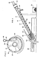
- FIG. 1 illustrates one embodiment of the apparatus for solid/liquid separation according to the invention.
- a screw conveyor 10 Contiguous to a lower end of the transporting tube 12 is arranged a hollow drum screen 20, into which is inserted a lower end of the conveyor 10.
- the drum screen 20 and the screw conveyor 10 are fixed to each other by means of, for example, a peripheral edge of screw vane for their integral rotation.
- the drum screen 20 is partially immersed in a coolant tank 22 which has a partially defined chamber 24 for an untreated coolant on the immersed side of the drum screen 20.
- a coolant supplying pipe 26 To the chamber 24 is connected a coolant supplying pipe 26.
- the transporting tube 12 at its upper end is provided with an outlet 28 for the separated solid, under which is arranged a collecting vessel 30 therefor.
- the drum screen 20 may be formed of a wedge wire or mesh screen of about 100 - 200 mesh size, a punched plate having attached a nylon or tetron net, or any other drum structures of permitting passage of the liquid but not the solid.
- the screw vane 32 at its peripheral edge is provided securely with a plurality of rods 34 as connecting means, which are circumferentially spaced apart from each other and extend in parallel to an axis of the screw conveyor 10, as shown in Figs. 2 and 3.
- These rods 34 are circumferentially covered with the drum screen 20 and fixed thereto at their contacted portions, thereby to achieve not only fixation but also reinforcement of the drum screen 20.
- a washing fluid supplying pipe 38 is extended along and above the drum screen 20 in the 1/4 rotational range of the screw conveyor 10 above a coolant level, and is provided with at least one injecting nozzle 40 which injects a washing fluid having a pressure of about 1 - 3 K g/cm 2 against the drum screen 20 for back-washing.
- the transporting tube 12 is inclined at an angle of about 30 but at any suitable degree for facilitating gravitational dehydration of the moving solid 36 and ensuring enough height of the outlet 28 for collecting the solid 36 into the vessel 30.
- too high inclination adversely affects transportation of the solid 36, and thus the inclination is preferably at not more than 45 , most preferably in the range of 25 to 35 .
- the electric motor 16 is driven for rotating the screw conveyor 10 together with the drum screen 20 through the reduction mechanism 18, while the coolant containing the solid (such as the machined chips) is introduced into the drum screen 20 through the receiving chamber 24 from the supplying pipe 26.
- the drum screen 20 filters the solid-containing coolant, and only the coolant passes through the drum screen 20 to be stored in the coolant tank 22.
- the separated solid 36 adheres to the inner wall of the drum screen 20 and is subjected to the back-washing action of the fluid from the injection nozzle 40.
- the washed solid falls onto the screw-conveyor 10 and is transported upward through the transporting tube 12. On the way through the transporting tube 12, the solid 36 is sufficiently dehydrated to be collected from the outlet 28 into the collecting vessel 30.
- the rotation rate of the drum screen 20 is set in the range of 1 to 50 r.p.m., preferably 5 to 20 r.p.m.
- the washing fluid for back-washing the drum screen 20 may be chosen depending on properties, such as viscosity, of the separated liquid and may be air or coolant free of the solid.
- the back-washing may be continuous, or intermittent if desired.
- FIG. 4 illustrates another embodiment of the apparatus according to the invention.
- the drum screen 20 and the screw conveyor 10 are placed horizontally.
- the screw conveyor 10 is constructed in a relatively short length, the front end of which is connected to the inclined transporting tube 12.
- the receiving chamber 24 for the untreated coolant is arranged at one end of the screen 20 on the upstream side of the screw conveyor 10, while the drum screen 20 at its other end is provided in fluid tight relation with a driving means including the electric motor 16 and the reduction mechanism 18 for rotating the shaft 14 of the screw conveyor 10.
- the coolant is supplied to the receiving chamber 24 for transporting the relatively coarse solid contained therein toward the outlet 28 on the screw conveyor 10, while the finer solid flows into the drum screen 20 for filtration to be deposited thereon and is transported successively on the screw conveyor 10 toward to the outlet 28.
- the transporting tube 12 at its inner bottom wall surrounding the screw conveyor 10 contiguous to the drum screen 20 is provided with at least one rail 42 contacted withthe screw vane 32 in parallel to the shaft 14 of the screw conveyor 10 for preventing accompanied rotation of the solid on the rotating screw conveyor 10, thereby to ensure better transportation.
- the solid 36 in the inclined transporting tube 12 is urged upward successively in its deposited state by a pushing force applied on the solid 36 by the screw conveyor 10.
- the . driving means for the screw conveyor 10 is arranged at one end of the drum screen 20 or at the downstream end of the screw conveyor 10 but, if desired, may be arranged at the upstream end of the screw conveyor 10 depending on the design of the apparatus.
- the rotating shaft to be rotated by the driving means may be inserted through the inclined transporting tube and joined by a universal joint or by fluid tight connection to the driving means outside the transporting tube 12 at the upstream end of the screw conveyor 10.
- Figures 5 and 6 illustrate another embodiment of the apparatus according to the invention, in which a disc screen 44 is used in place of the drum screen of the previous embodiment.
- the disc screen 44 is arranged at one end side of the horizontal screw conveyor 10, as in Fig. 4, but normally to the shaft 14 for rotation integrally therewith.
- Other components, namely the transporting tube 12, the receiving chamber 24 for the untreated coolant and the driving means for the screw conveyor 10 are substantially identical to those of the embodiment in Fig. 4, and are represented by the same references as in Fig. 4 and may be omitted for their description.
- the disc screen 44 in this embodiment may be constructed with the same material as for the drum screen and is arranged securely at one side face of a given circular supporting element 46 which is fixed to the shaft 14 of the screw conveyor 10.
- the supporting element 46 is composed of a boss 48, a plurality of arms 50 and a rim 52. Then, the disc screen 44 at its center is fixed to a portion of the boss 48 while at its outer end is contacted with an outer periphery of the rim 52, which is fixed by an annular element 54.
- the circular supporting element 46 allows the annular element 54 thereon to contact slidably and fluid-tightly to a sealing 56 provided on an inner circumference of the transporting tube 12.
- the substantially same effect of filtering the solids may be achieved as in the previous embodiment.
- its back-washing is ensured by arranging the injection nozzle 40 above the disc screen 44 and against an outer side face of the latter.
- the solid/liquid separation may be achieved by means of the screw conveyor and the screen of the drum or disc form rotatable integrally therewith, and that the separated solid may be transported and collected efficiently by the screw conveyor. Further, the screen may be back-washed continuously or intermittently by the washing fluid, thereby to prevent clogging due to adhesion of the solid, to maintain the effective solid/liquid separation and to enhance the treating capacity considerably.
- the apparatus according to the invention may be constructed in a compact type, requires less space for placement, and is convenient in maintenance of the screen with its separating function, thereby to significantly reduce the production and maintenance cost of the apparatus.
- the apparatus according to the invention may be widely applied to various machine tools, such as a cutter, a grinder, a rolling mill, a scrubber, a honing machine and others, for separating inorganic suspended matter (such as iron chips) from a machining oil or an engine oil, or to solid-liquid separators for liquid containing sands or activated carbons, and that many variations and modifications may be made without departing from the true spirit and scope of the invention.
- machine tools such as a cutter, a grinder, a rolling mill, a scrubber, a honing machine and others, for separating inorganic suspended matter (such as iron chips) from a machining oil or an engine oil, or to solid-liquid separators for liquid containing sands or activated carbons, and that many variations and modifications may be made without departing from the true spirit and scope of the invention.
Landscapes
- Chemical & Material Sciences (AREA)
- Chemical Kinetics & Catalysis (AREA)
- Auxiliary Devices For Machine Tools (AREA)
- Centrifugal Separators (AREA)
- Filtration Of Liquid (AREA)
- Separation Of Solids By Using Liquids Or Pneumatic Power (AREA)
Abstract
Description
- This invention relates to an apparatus for filtering solid from solid-containing liquid through a screen and transporting the separated solid.
- Heretofore, various apparatus for removing relatively large machined chips have been proposed and utilized for treating these chips as produced by machine tools. However, these apparatus cannot remove fine chips, which in turn are collected together with a machining fluid in a coolant tank and precipitated therein. Thus, if a large amount of the fine chips recipitates in the coolant tank, a capacity of the tank is insufficient for coolant, which overflows from the tank. As a result, a fire accident may occur due to oil property of the coolant. Further, circulation of the unremoved chips together with the chips may block an ejecting nozzle for the coolant thereby to cause damage of the tools and worse quality of machined works.
- Furthermore, a setting disorder may arise in a machining center upon replacement of automatic tools, thereby to adversely affect a machining accuracy.
- In veiw of the foregoing, an apparatus of such a type has been proposed that a conventional coolant tank is provided at its inner bottom with a screw conveyor for removing the precipitated chips therefrom. In such type of apparatus, however, the conveyor was generally arranged horizontally in consideration of its conveying capacity and was impossible to be arranged obliquely for the purpose of reducing a setting area.
- Since most of the machined chips are generally magnetic in nature, an apparatus provided at its bottom with a magnetic plate has also been proposed to aggregate the magnetic chips at the bottom within the tank, from which they are scraped and removed by a scraper. Such apparatus, however, necessitates also enlargement of a setting area for the magnetic plate in order to increase the aggregation, thereby to require a large size of the scraper. Thus, the apparatus becomes necessarily large, thereby to raise an equipment cost. Such apparatus has a further disadvantage in that only very limited amount of non-magnetic chips can be removed.
- For solving the foregoing problems, there has been proposed an apparatus for filtering the chips from chip-containing liquid, such as an coolant, by use of a filtering means, such as a screen, and transporting the chips on a screw conveyor, as disclosed in U.S. Patent 3,585,924. However, the apparatus of such type often becomes impossible to filter the chips due to adhesion and clogging of the chips to the filtering means, and thus requires periodical stoppage of the screw conveyor for cleaning the filtering means, resulting in a time-consuming, trouble-some and inefficient operation.
- Accordingly, it has long been needed to provide an apparatus for treating chips, which is compact and achieve efficient recovery and removal of the chips, as well as reduction of the equipment cost.
- It was now been found out that floating or precipitating solids in liquid may be surely filtered by arrangements in which a screw conveyor at its one end is provided with a screen of a hollow drum or disc form rotatable integrally therewith and having one end for serving as an inlet for the solid-containing liquid, and in which an injecting nozzle is arranged above the screen for injecting fluid inside the screen, resulting in the effective cleaning of the screen and thus efficient operation of the apparatus.
- Due to its ability of effective and continuous filteration of the solids through the screen, the apparatus may be compact in construction. Further, due to rising arrangement and short length of the screw conveyor, the apparatus requires less volume and thus less space for its placement.
- Accordingly, an object of the invention is to provide an apparatus for separation and transportation of solid from liguid, which has been several advantages of compactness, efficient filtration, convenient maintenance, small space for placement, and reduced cost for equipment.
- In view of the foregoing, this invention provides an apparatus for separation and transportation of solid from liquid, which comprises a screw conveyor; a transporting tube containing said scerw conveyor; a screen of a hollow drum or disc adjacent to one end of said transporting tube, said screw conveyor extending integrally inside said screen; a receiving chamber for solid-containing liquid arranged at one end of said screen; at least one injection nozzle for a back-washing fluid arranged above an upper side of said screen; and a rotational driving means connected to one end of said screw conveyor.
- The invention will be described hereinbelow in more detail for better understanding with reference to preferred embodiments of the accompanying drawings.
- Figure 1 is a schematic sectional side view of a typical embodiment of the apparatus according to the invention;
- Figure 2 is an enlarged sectional view of the apparatus taken along the line II-II in Fig. 1, showing its working state;
- Figure 3 is a sectional side view of main portions of the apparatus in Fig. 1, showing detailed construction of the drum screen;
- Figure 4 is a schematic sectional side view of another embodiment of the apparatus according to the invention.
- Figure 5 is a schematic sectional view of main portions of another embodiment according to the invention; and
- Figure 6 is an enlarged sectional view of main portions taken along the line VI-VI in Fig. 5.
- Figures 1 and 2 illustrate one embodiment of the apparatus for solid/liquid separation according to the invention. Referring to Fig. 1, there are shown a
screw conveyor 10, atransporting tube 12 containing the screw conveyor, ashaft 14 of the screw conveyor, anelectric motor 16 for driving the screw conveyor, and areduction mechanism 18 connected to an output shaft of the electric motor. Contiguous to a lower end of the transportingtube 12 is arranged ahollow drum screen 20, into which is inserted a lower end of theconveyor 10. Thedrum screen 20 and thescrew conveyor 10 are fixed to each other by means of, for example, a peripheral edge of screw vane for their integral rotation. Thedrum screen 20 is partially immersed in acoolant tank 22 which has a partially definedchamber 24 for an untreated coolant on the immersed side of thedrum screen 20. To thechamber 24 is connected acoolant supplying pipe 26. On the other hand, thetransporting tube 12 at its upper end is provided with anoutlet 28 for the separated solid, under which is arranged acollecting vessel 30 therefor. - In accordance with the invention, the
drum screen 20 may be formed of a wedge wire or mesh screen of about 100 - 200 mesh size, a punched plate having attached a nylon or tetron net, or any other drum structures of permitting passage of the liquid but not the solid. In order to allow thedrum screen 20 to rotate integrally with thescrew conveyor 10, thescrew vane 32 at its peripheral edge is provided securely with a plurality ofrods 34 as connecting means, which are circumferentially spaced apart from each other and extend in parallel to an axis of thescrew conveyor 10, as shown in Figs. 2 and 3. Theserods 34 are circumferentially covered with thedrum screen 20 and fixed thereto at their contacted portions, thereby to achieve not only fixation but also reinforcement of thedrum screen 20. In thedrum screen 20 thus constructed, as shown in Fig. 2, the solid 36 (such as machined chips) deposited on thescrew conveyor 10 tends to adhere to an inner wall of thedrum screen 20 and to move upwardly with rotation of thescrew conveyor 10. Taking this trend into consideration, a washingfluid supplying pipe 38 is extended along and above thedrum screen 20 in the 1/4 rotational range of thescrew conveyor 10 above a coolant level, and is provided with at least one injectingnozzle 40 which injects a washing fluid having a pressure of about 1 - 3 Kg/cm2 against thedrum screen 20 for back-washing. - As shown in Fig. 1, the
transporting tube 12 is inclined at an angle of about 30 but at any suitable degree for facilitating gravitational dehydration of the moving solid 36 and ensuring enough height of theoutlet 28 for collecting the solid 36 into thevessel 30. However, too high inclination adversely affects transportation of the solid 36, and thus the inclination is preferably at not more than 45 , most preferably in the range of 25 to 35 . - In the apparatus of this embodiment, the
electric motor 16 is driven for rotating thescrew conveyor 10 together with thedrum screen 20 through thereduction mechanism 18, while the coolant containing the solid (such as the machined chips) is introduced into thedrum screen 20 through thereceiving chamber 24 from the supplyingpipe 26. Then, thedrum screen 20 filters the solid-containing coolant, and only the coolant passes through thedrum screen 20 to be stored in thecoolant tank 22. The separated solid 36 adheres to the inner wall of thedrum screen 20 and is subjected to the back-washing action of the fluid from theinjection nozzle 40. Then, the washed solid falls onto the screw-conveyor 10 and is transported upward through thetransporting tube 12. On the way through the transportingtube 12, the solid 36 is sufficiently dehydrated to be collected from theoutlet 28 into thecollecting vessel 30. - If the rotation rate of the
drum screen 20 is too high, the solid 36 remains adhered to the inner wall of thedrum screen 20 by a centrifugal force and becomes impossible to fall down by its own weight and difficult to be transported by thescrew conveyor 10. For this reason, the rotation rate of thedrum screen 20 is set in the range of 1 to 50 r.p.m., preferably 5 to 20 r.p.m. The washing fluid for back-washing thedrum screen 20 may be chosen depending on properties, such as viscosity, of the separated liquid and may be air or coolant free of the solid. The back-washing may be continuous, or intermittent if desired. - Figure 4 illustrates another embodiment of the apparatus according to the invention. For convenience of the illustration, components identical to those in the previous embodiment are shown with the same references and omitted for their description. In this embodiment, the
drum screen 20 and thescrew conveyor 10 are placed horizontally. For this purposse, thescrew conveyor 10 is constructed in a relatively short length, the front end of which is connected to theinclined transporting tube 12. In this case, thereceiving chamber 24 for the untreated coolant is arranged at one end of thescreen 20 on the upstream side of thescrew conveyor 10, while thedrum screen 20 at its other end is provided in fluid tight relation with a driving means including theelectric motor 16 and thereduction mechanism 18 for rotating theshaft 14 of thescrew conveyor 10. According to the apparatus thus constructed, the coolant is supplied to thereceiving chamber 24 for transporting the relatively coarse solid contained therein toward theoutlet 28 on thescrew conveyor 10, while the finer solid flows into thedrum screen 20 for filtration to be deposited thereon and is transported successively on thescrew conveyor 10 toward to theoutlet 28. In this embodiment, thetransporting tube 12 at its inner bottom wall surrounding thescrew conveyor 10 contiguous to thedrum screen 20 is provided with at least onerail 42 contacted withthescrew vane 32 in parallel to theshaft 14 of thescrew conveyor 10 for preventing accompanied rotation of the solid on the rotatingscrew conveyor 10, thereby to ensure better transportation. Further, the solid 36 in theinclined transporting tube 12 is urged upward successively in its deposited state by a pushing force applied on the solid 36 by thescrew conveyor 10. - According to the embodiment as shown in Fig. 4, the . driving means for the
screw conveyor 10 is arranged at one end of thedrum screen 20 or at the downstream end of thescrew conveyor 10 but, if desired, may be arranged at the upstream end of thescrew conveyor 10 depending on the design of the apparatus. In the latter case, the rotating shaft to be rotated by the driving means may be inserted through the inclined transporting tube and joined by a universal joint or by fluid tight connection to the driving means outside the transportingtube 12 at the upstream end of thescrew conveyor 10. - Figures 5 and 6 illustrate another embodiment of the apparatus according to the invention, in which a
disc screen 44 is used in place of the drum screen of the previous embodiment. Thedisc screen 44 is arranged at one end side of thehorizontal screw conveyor 10, as in Fig. 4, but normally to theshaft 14 for rotation integrally therewith. Other components, namely thetransporting tube 12, thereceiving chamber 24 for the untreated coolant and the driving means for thescrew conveyor 10 are substantially identical to those of the embodiment in Fig. 4, and are represented by the same references as in Fig. 4 and may be omitted for their description. - The
disc screen 44 in this embodiment may be constructed with the same material as for the drum screen and is arranged securely at one side face of a given circular supportingelement 46 which is fixed to theshaft 14 of thescrew conveyor 10. The supportingelement 46 is composed of aboss 48, a plurality ofarms 50 and arim 52. Then, thedisc screen 44 at its center is fixed to a portion of theboss 48 while at its outer end is contacted with an outer periphery of therim 52, which is fixed by anannular element 54. The circular supportingelement 46 allows theannular element 54 thereon to contact slidably and fluid-tightly to a sealing 56 provided on an inner circumference of the transportingtube 12. - With the
disc screen 44 thus constructed, the substantially same effect of filtering the solids may be achieved as in the previous embodiment. According to the embodiment using thedisc screen 44, its back-washing is ensured by arranging theinjection nozzle 40 above thedisc screen 44 and against an outer side face of the latter. - In accordance with the invention, it will be appreciated that the solid/liquid separation may be achieved by means of the screw conveyor and the screen of the drum or disc form rotatable integrally therewith, and that the separated solid may be transported and collected efficiently by the screw conveyor. Further, the screen may be back-washed continuously or intermittently by the washing fluid, thereby to prevent clogging due to adhesion of the solid, to maintain the effective solid/liquid separation and to enhance the treating capacity considerably.
- Thus, the apparatus according to the invention may be constructed in a compact type, requires less space for placement, and is convenient in maintenance of the screen with its separating function, thereby to significantly reduce the production and maintenance cost of the apparatus.
- Although the invention has been described hereinabove with the preferred embodiments, it will be appreciated that the apparatus according to the invention may be widely applied to various machine tools, such as a cutter, a grinder, a rolling mill, a scrubber, a honing machine and others, for separating inorganic suspended matter (such as iron chips) from a machining oil or an engine oil, or to solid-liquid separators for liquid containing sands or activated carbons, and that many variations and modifications may be made without departing from the true spirit and scope of the invention.
Claims (6)
Applications Claiming Priority (2)
| Application Number | Priority Date | Filing Date | Title |
|---|---|---|---|
| JP1984146615U JPS6164347U (en) | 1984-09-29 | 1984-09-29 | |
| JP146615/84U | 1984-09-29 |
Publications (3)
| Publication Number | Publication Date |
|---|---|
| EP0177451A2 true EP0177451A2 (en) | 1986-04-09 |
| EP0177451A3 EP0177451A3 (en) | 1987-04-15 |
| EP0177451B1 EP0177451B1 (en) | 1989-04-19 |
Family
ID=15411742
Family Applications (1)
| Application Number | Title | Priority Date | Filing Date |
|---|---|---|---|
| EP85810443A Expired EP0177451B1 (en) | 1984-09-29 | 1985-09-26 | An apparatus for separation and transportation of solid from liquid |
Country Status (5)
| Country | Link |
|---|---|
| EP (1) | EP0177451B1 (en) |
| JP (1) | JPS6164347U (en) |
| KR (1) | KR860002292A (en) |
| CA (1) | CA1259033A (en) |
| DE (1) | DE3569478D1 (en) |
Cited By (9)
| Publication number | Priority date | Publication date | Assignee | Title |
|---|---|---|---|---|
| GB2195913A (en) * | 1986-09-23 | 1988-04-20 | Mitchell Cotts Mining Equipmen | A screening assembly |
| WO2000040320A1 (en) * | 1999-01-08 | 2000-07-13 | Meri Entsorgungstechnik für die Papierindustrie GmbH | Device for separating fluids |
| EP1275297A1 (en) * | 2001-06-26 | 2003-01-15 | 625606 B.C. Ltd. | Solid-liquid separating apparatus |
| WO2004087289A1 (en) * | 2003-04-04 | 2004-10-14 | Hans Huber Ag Maschinen- Und Anlagenbau | Device for removing fine screened material from a liquid |
| CN106319219A (en) * | 2015-06-18 | 2017-01-11 | 蒋满珍 | Copper powder recovery device |
| CN107288560A (en) * | 2017-07-17 | 2017-10-24 | 长江大学 | A kind of helix transporting device with filtering slurry function |
| CN112023497A (en) * | 2020-09-25 | 2020-12-04 | 邵维芳 | Water pollution treatment impurity separation equipment and separation method |
| CN115889170A (en) * | 2022-11-04 | 2023-04-04 | 云南滇东雨汪能源有限公司 | Coal transportation system, sorting assembly and device |
| CN118477381A (en) * | 2024-07-16 | 2024-08-13 | 潍坊大明生物科技有限公司 | Separation device and process for preparing oleic acid |
Family Cites Families (4)
| Publication number | Priority date | Publication date | Assignee | Title |
|---|---|---|---|---|
| DE1177573B (en) * | 1962-04-16 | 1964-09-10 | Guenter Kuhnt | Rising conveyor screw for dewatering bulk goods |
| GB1093948A (en) * | 1964-04-15 | 1967-12-06 | G & J Weir Ltd | Combined conveyor and filter device |
| US3585924A (en) * | 1969-03-10 | 1971-06-22 | William J Nolan | Apparatus for the removal of liquids from fibrous materials |
| US4384955A (en) * | 1980-11-25 | 1983-05-24 | Shinji Nakakura | Chips-deoiling machine |
-
1984
- 1984-09-29 JP JP1984146615U patent/JPS6164347U/ja active Pending
-
1985
- 1985-09-24 CA CA000491401A patent/CA1259033A/en not_active Expired
- 1985-09-26 DE DE8585810443T patent/DE3569478D1/en not_active Expired
- 1985-09-26 EP EP85810443A patent/EP0177451B1/en not_active Expired
- 1985-09-27 KR KR1019850007168A patent/KR860002292A/en not_active Withdrawn
Cited By (12)
| Publication number | Priority date | Publication date | Assignee | Title |
|---|---|---|---|---|
| GB2195913A (en) * | 1986-09-23 | 1988-04-20 | Mitchell Cotts Mining Equipmen | A screening assembly |
| WO2000040320A1 (en) * | 1999-01-08 | 2000-07-13 | Meri Entsorgungstechnik für die Papierindustrie GmbH | Device for separating fluids |
| EP1275297A1 (en) * | 2001-06-26 | 2003-01-15 | 625606 B.C. Ltd. | Solid-liquid separating apparatus |
| WO2004087289A1 (en) * | 2003-04-04 | 2004-10-14 | Hans Huber Ag Maschinen- Und Anlagenbau | Device for removing fine screened material from a liquid |
| US7344637B2 (en) | 2003-04-04 | 2008-03-18 | Hans Huber Ag Maschinen-Und Anlagenbau | Apparatus for removing fine material from a liquid |
| CN106319219A (en) * | 2015-06-18 | 2017-01-11 | 蒋满珍 | Copper powder recovery device |
| CN107288560A (en) * | 2017-07-17 | 2017-10-24 | 长江大学 | A kind of helix transporting device with filtering slurry function |
| CN107288560B (en) * | 2017-07-17 | 2023-05-26 | 长江大学 | Screw conveyer with mud filtering capability |
| CN112023497A (en) * | 2020-09-25 | 2020-12-04 | 邵维芳 | Water pollution treatment impurity separation equipment and separation method |
| CN115889170A (en) * | 2022-11-04 | 2023-04-04 | 云南滇东雨汪能源有限公司 | Coal transportation system, sorting assembly and device |
| CN115889170B (en) * | 2022-11-04 | 2023-08-15 | 云南滇东雨汪能源有限公司 | Coal transportation system, sorting assembly and device |
| CN118477381A (en) * | 2024-07-16 | 2024-08-13 | 潍坊大明生物科技有限公司 | Separation device and process for preparing oleic acid |
Also Published As
| Publication number | Publication date |
|---|---|
| EP0177451A3 (en) | 1987-04-15 |
| EP0177451B1 (en) | 1989-04-19 |
| CA1259033A (en) | 1989-09-05 |
| DE3569478D1 (en) | 1989-05-24 |
| KR860002292A (en) | 1986-04-24 |
| JPS6164347U (en) | 1986-05-01 |
Similar Documents
| Publication | Publication Date | Title |
|---|---|---|
| CA1302302C (en) | Apparatus for separation of solid from liquid | |
| US6571959B1 (en) | Coolant fluid cleaning method and apparatus | |
| US3262573A (en) | Filter apparatus | |
| JP2003511216A (en) | Equipment for filtering contaminated liquids | |
| US3241675A (en) | Rotary filter and method | |
| EP0755293B1 (en) | A rotating disc filter means | |
| EP0177451B1 (en) | An apparatus for separation and transportation of solid from liquid | |
| US6274037B1 (en) | Coolant purification system | |
| US20060049112A1 (en) | Coolant fluid cleaning method, system, and apparatus | |
| JP3677371B2 (en) | Liquid purification method and apparatus | |
| JP4122348B2 (en) | Apparatus and method for separating and recovering waste liquid-containing components such as recovered coolant | |
| JP2003154215A (en) | Solid-liquid separating apparatus | |
| US4818419A (en) | Method of removing clogging material from a clogged granular filter medium | |
| KR100380225B1 (en) | A continuous filter's auto back wash device used cyclone methode | |
| JP2007098538A (en) | Solid-liquid separation system | |
| EP1044713A1 (en) | Method and device for clarifying a liquid flow containing finely divided solids | |
| CN214714974U (en) | Underground coal slurry water treatment system for coal mine | |
| JPH0520850U (en) | Bucket conveyor type separator for non-magnetic material | |
| JP4794267B2 (en) | Precipitation separator | |
| JPH1190763A (en) | Drum filter type separator | |
| CN223602147U (en) | A screening and slag removal device and a waste edible oil purification device | |
| JP2582464Y2 (en) | Single overflow solid-liquid separator | |
| US3669269A (en) | Industrial plant for recovering solids from liquids | |
| JPH09295242A (en) | Liquid processing equipment | |
| JPH0957570A (en) | Liquid processing equipment for machine tools |
Legal Events
| Date | Code | Title | Description |
|---|---|---|---|
| PUAI | Public reference made under article 153(3) epc to a published international application that has entered the european phase |
Free format text: ORIGINAL CODE: 0009012 |
|
| AK | Designated contracting states |
Kind code of ref document: A2 Designated state(s): BE CH DE FR GB IT LI |
|
| PUAL | Search report despatched |
Free format text: ORIGINAL CODE: 0009013 |
|
| AK | Designated contracting states |
Kind code of ref document: A3 Designated state(s): BE CH DE FR GB IT LI |
|
| 17P | Request for examination filed |
Effective date: 19870618 |
|
| 17Q | First examination report despatched |
Effective date: 19880310 |
|
| ITF | It: translation for a ep patent filed | ||
| GRAA | (expected) grant |
Free format text: ORIGINAL CODE: 0009210 |
|
| AK | Designated contracting states |
Kind code of ref document: B1 Designated state(s): BE CH DE FR GB IT LI |
|
| REF | Corresponds to: |
Ref document number: 3569478 Country of ref document: DE Date of ref document: 19890524 |
|
| ET | Fr: translation filed | ||
| PLBE | No opposition filed within time limit |
Free format text: ORIGINAL CODE: 0009261 |
|
| STAA | Information on the status of an ep patent application or granted ep patent |
Free format text: STATUS: NO OPPOSITION FILED WITHIN TIME LIMIT |
|
| 26N | No opposition filed | ||
| PGFP | Annual fee paid to national office [announced via postgrant information from national office to epo] |
Ref country code: CH Payment date: 19910724 Year of fee payment: 7 |
|
| PGFP | Annual fee paid to national office [announced via postgrant information from national office to epo] |
Ref country code: FR Payment date: 19910812 Year of fee payment: 7 |
|
| PGFP | Annual fee paid to national office [announced via postgrant information from national office to epo] |
Ref country code: GB Payment date: 19910814 Year of fee payment: 7 |
|
| PGFP | Annual fee paid to national office [announced via postgrant information from national office to epo] |
Ref country code: DE Payment date: 19910828 Year of fee payment: 7 Ref country code: BE Payment date: 19910828 Year of fee payment: 7 |
|
| ITTA | It: last paid annual fee | ||
| PG25 | Lapsed in a contracting state [announced via postgrant information from national office to epo] |
Ref country code: GB Effective date: 19920926 |
|
| PG25 | Lapsed in a contracting state [announced via postgrant information from national office to epo] |
Ref country code: LI Effective date: 19920930 Ref country code: CH Effective date: 19920930 Ref country code: BE Effective date: 19920930 |
|
| BERE | Be: lapsed |
Owner name: INABAC CORP. Effective date: 19920930 |
|
| GBPC | Gb: european patent ceased through non-payment of renewal fee |
Effective date: 19920926 |
|
| PG25 | Lapsed in a contracting state [announced via postgrant information from national office to epo] |
Ref country code: FR Effective date: 19930528 |
|
| REG | Reference to a national code |
Ref country code: CH Ref legal event code: PL |
|
| PG25 | Lapsed in a contracting state [announced via postgrant information from national office to epo] |
Ref country code: DE Effective date: 19930602 |
|
| REG | Reference to a national code |
Ref country code: FR Ref legal event code: ST |