EP0177331A2 - Verfahren und Vorrichtung zum Darstellen von Wellenformen auf einer Flüssigkristallsichtanzeige - Google Patents
Verfahren und Vorrichtung zum Darstellen von Wellenformen auf einer Flüssigkristallsichtanzeige Download PDFInfo
- Publication number
- EP0177331A2 EP0177331A2 EP85307010A EP85307010A EP0177331A2 EP 0177331 A2 EP0177331 A2 EP 0177331A2 EP 85307010 A EP85307010 A EP 85307010A EP 85307010 A EP85307010 A EP 85307010A EP 0177331 A2 EP0177331 A2 EP 0177331A2
- Authority
- EP
- European Patent Office
- Prior art keywords
- conductive elements
- input signal
- voltage
- screen
- predetermined
- Prior art date
- Legal status (The legal status is an assumption and is not a legal conclusion. Google has not performed a legal analysis and makes no representation as to the accuracy of the status listed.)
- Withdrawn
Links
Images


Classifications
-
- G—PHYSICS
- G02—OPTICS
- G02F—OPTICAL DEVICES OR ARRANGEMENTS FOR THE CONTROL OF LIGHT BY MODIFICATION OF THE OPTICAL PROPERTIES OF THE MEDIA OF THE ELEMENTS INVOLVED THEREIN; NON-LINEAR OPTICS; FREQUENCY-CHANGING OF LIGHT; OPTICAL LOGIC ELEMENTS; OPTICAL ANALOGUE/DIGITAL CONVERTERS
- G02F1/00—Devices or arrangements for the control of the intensity, colour, phase, polarisation or direction of light arriving from an independent light source, e.g. switching, gating or modulating; Non-linear optics
- G02F1/01—Devices or arrangements for the control of the intensity, colour, phase, polarisation or direction of light arriving from an independent light source, e.g. switching, gating or modulating; Non-linear optics for the control of the intensity, phase, polarisation or colour
- G02F1/13—Devices or arrangements for the control of the intensity, colour, phase, polarisation or direction of light arriving from an independent light source, e.g. switching, gating or modulating; Non-linear optics for the control of the intensity, phase, polarisation or colour based on liquid crystals, e.g. single liquid crystal display cells
- G02F1/133—Constructional arrangements; Operation of liquid crystal cells; Circuit arrangements
- G02F1/1333—Constructional arrangements; Manufacturing methods
- G02F1/1345—Conductors connecting electrodes to cell terminals
-
- G—PHYSICS
- G01—MEASURING; TESTING
- G01R—MEASURING ELECTRIC VARIABLES; MEASURING MAGNETIC VARIABLES
- G01R13/00—Arrangements for displaying electric variables or waveforms
- G01R13/40—Arrangements for displaying electric variables or waveforms using modulation of a light beam otherwise than by mechanical displacement, e.g. by Kerr effect
- G01R13/404—Arrangements for displaying electric variables or waveforms using modulation of a light beam otherwise than by mechanical displacement, e.g. by Kerr effect for discontinuous display, i.e. display of discrete values
- G01R13/408—Two or three dimensional representation of measured values
-
- H—ELECTRICITY
- H05—ELECTRIC TECHNIQUES NOT OTHERWISE PROVIDED FOR
- H05K—PRINTED CIRCUITS; CASINGS OR CONSTRUCTIONAL DETAILS OF ELECTRIC APPARATUS; MANUFACTURE OF ASSEMBLAGES OF ELECTRICAL COMPONENTS
- H05K3/00—Apparatus or processes for manufacturing printed circuits
- H05K3/30—Assembling printed circuits with electric components, e.g. with resistor
- H05K3/32—Assembling printed circuits with electric components, e.g. with resistor electrically connecting electric components or wires to printed circuits
- H05K3/325—Assembling printed circuits with electric components, e.g. with resistor electrically connecting electric components or wires to printed circuits by abutting or pinching, i.e. without alloying process; mechanical auxiliary parts therefor
-
- H—ELECTRICITY
- H05—ELECTRIC TECHNIQUES NOT OTHERWISE PROVIDED FOR
- H05K—PRINTED CIRCUITS; CASINGS OR CONSTRUCTIONAL DETAILS OF ELECTRIC APPARATUS; MANUFACTURE OF ASSEMBLAGES OF ELECTRICAL COMPONENTS
- H05K3/00—Apparatus or processes for manufacturing printed circuits
- H05K3/36—Assembling printed circuits with other printed circuits
- H05K3/368—Assembling printed circuits with other printed circuits parallel to each other
-
- Y—GENERAL TAGGING OF NEW TECHNOLOGICAL DEVELOPMENTS; GENERAL TAGGING OF CROSS-SECTIONAL TECHNOLOGIES SPANNING OVER SEVERAL SECTIONS OF THE IPC; TECHNICAL SUBJECTS COVERED BY FORMER USPC CROSS-REFERENCE ART COLLECTIONS [XRACs] AND DIGESTS
- Y10—TECHNICAL SUBJECTS COVERED BY FORMER USPC
- Y10S—TECHNICAL SUBJECTS COVERED BY FORMER USPC CROSS-REFERENCE ART COLLECTIONS [XRACs] AND DIGESTS
- Y10S359/00—Optical: systems and elements
- Y10S359/90—Methods
Definitions
- the invention relates to devices for presenting visual displays of input signals such as the displays shown on cathode ray tubes (CRT's). More particularly, the present invention relates to display devices utilizing liquid crystals and electrode and scanning arrangements therefor.
- CTR's cathode ray tubes
- liquid crystal materials in which the propagation or characteristics of light incidence thereon can be altered by inducing an electric or magnetic field in the liquid crystal material.
- liquid crystal materials include, but are not limited to, nematic liquid crystal materials possessing dynamic or quiescent scattering, or twisted field-effect electro-optical f properties, and the mixtures of these nematic liquid crystal materials with cholesteric liquid crystal materials.
- a dynamic scattering liquid crystal material In a dynamic scattering liquid crystal material, light is transmitted substantially unaffected through the material in the absence of an electric field across the liquid material. When an electric field of sufficient magnitude is induced in the liquid crystal material, light incident upon the material is optically scattered and transmission of light through the material is substantially prevented.
- a quiescent scattering liquid crystal material possesses field effective electro-optical properties which are the converse of those of the dynamic scattering liquid crystal. Thus, in the absence of an electric field, the quiescent scattering liquid crystal material scatters incident light, while an electric field induced in the quiescent liquid crystal material causes it to transmit incident light therethrough.
- a twisted nematic liquid crystal material layers of molecules at opposed surfaces of the material can be caused to be aligned at an angle with each other in the absence of a field.
- the molecules between the opposed surfaces have varying angular alignments with the result that the molecular orientation through the material from one surface to the other is helical of "twisted".
- the plane of polarization of plane polarized light is rotated by the angle formed by the opposed surface molecules as the light passes through the liquid crystal material in the absence of a field.
- the application of an electric field to the material destroys the twisted alignment of the molecules with the result that the material transmits incident plane polarized light therethrough without. substantial rotation of the plane of polarization.
- Cathode-ray tube oscilloscopes are used to produce a luminous plot on a fluorescent screen which is the graphical representation of an electric signal being used as the input. Motion of a focused spot leaves a visible trace on the phosphor on the viewing screen of the tube.
- the primary advantage of cathode-ray oscillescopes over other forms of plotting devices is its speed of response. Commercially available instruments can display frequencies as high as 2 GHz.
- Liquid crystal materials of the types referred to above, as well as others, are well known in the prior art. See, for example, G. Heilmeier, "Liquid-Crystal Display Device", Scientific American, April, 1970, pp. 100-106; G. Heilmeier, L. Zanoni & L. Barton, "Dynamic Scattering: A New Electro-optic Effect in Certain Classes of Nematic Liquid Crystals", Proceedings of the IEEE, Vol. 56, No. 7, July 1968, pp. 1162-1171; and U.S. Patent No. 3,918,796, issued on November 11, 1975, to Fergason.
- Nematic scattering liquid crystal electro-optical elements are well known in the prior art, as described, for example, in U.S. Patent No. 3,322,485, issued on May 30, 1967, to Williams. Twisted liquid crystal electro-optical elements which require the use of polarizing elements, are also well known in the art, as described, for example, in the aforementioned Fergason '796 patent.
- the Fergason '796 patent and U.S. Patent No. 3,834,792, issued on September 10, 1976, to Janning, describe two arrangements for aligning liquid crystal molecules in a display in order that polarized light passing through the material in the absence of an electric field is rotated.
- the Fergason '796 patent teaches rubbing each of the glass plates which enclose the liquid crystal material in a single predetermined direction and thereafter positioning the plates with the directions of rubbing of the plates forming an angle through which the polarized light is to be rotated.
- the Janning '792 patent teaches the growth of an alignment film on each plate and then the arranging of the plates with the directions of growth on each of the plates forming a desired angle with respect to one another.
- Both the Fergason '796 and the Janning '792 patents disclose arrangements of polarizers and twisted liquid crystal cells.
- the '875 patent also discloses scanning devices incorporating such dielectrics. The disclosure of the '875 patent is incorporated herein by reference.
- U.S. Patent No. 3,807,831 issued on April 30, 1974 to-Soref discloses a liquid crystal display device which includes interleaved arrays of alternate parallel electrodes. A field is induced between interleaved electrodes.
- Optoceramic devices are disclosed in C.E. Land, P.D. Thatcher and G.H. Haertling, Electro-optic Ceramics, Academic Press, 1974 at pages 137-233.
- Liquid crystals and liquid crystal displays are described in 14 R. Kirk & D. Othmer, Encyclopedia of Chemical Technology 395-427 (3d ed 1981) and 7 R. Kirk & D. Othmer, ' supra, at 726-33 (3d ed. 1979), the teachings of which are incorporated by reference. Liquid crystal displays are commonly used in calculators and digital watches, and thin screen television displays are being introduced.
- twisted-nematic field effect in oscilloscope displays has the advantages of very low power consumption and voltage threshold, improved lifetime, a wide viewing angle in the reflecting mode, and is not subject to image washout at high ambient light levels.
- Information is displayed by analog addressing techniques that render null points along an x-y grid.
- liquid crystal oscilloscopes Despite the numerous advantages of utilizing liquid crystal displays, they have been heretofore unable to provide a practical alternative to cathode-ray oscilloscopes because of the inability to achieve speeds of response matching those of commercially available oscilloscopes. This problem is alleviated by the use of analog multiplexing techniques in order to scan the liquid crystal display.
- a grid is formed by two interleaved arrays of alternate parallel electrodes.
- An analog. multiplexer is used to scan the display by addressing one line at a time along one of the arrays.
- the liquid crystal oscilloscope described herein is capable of displaying waveforms of electric signals with frequencies as high as 1 MHz.
- the liquid crystal oscilloscope described herein is capable of multiplexing, by way of example, sixty-four vertical lines with a clock operating at a frequency of 64 MHz without the problems described above.
- the number of multiplexed lines can be increased in order to provide better resolution and a larger display. Increasing the number of multiplexed lines results in longer times to complete the scan of all of the lines.
- Each line being addressed is isolated from the others and functions like a sample-and-hold circuit with the liquid crystal and interleaved electrodes acting as a capacitor and the high impedance switching device connected to the vertical lines, such as a multiplexer, constituting the resistive component. Since each channel is analog, a gray scale exists at the portions of a vertical strip immediately above and below the actual null points. The gray scale enables use of a minimum of multiplexer channels in order to achieve suitable resolution.
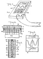
- the display device of the invention can be made in a compact and light-weight form which is battery-powered. Accordingly, the display device is readily adaptable to serve as a portable oscilloscope, portable EKG device, or in applications where a compact oscilloscope is of advantage.
- Display device 10 includes a liquid crystal display 11, or viewing screen, having a first transparent plate 12 which is maintained in closely spaced relation to a second transparent plate 14 by means of a peripheral sealing member 16.
- the lines extend vertically when the front surface 10a of display device 10 is disposed in a vertical plane.
- the lines 20 can be formed by a use of a photo-resist material and an etching process.
- each of lines 20 may have a width of approximately .007-.010 mm.
- display device 10 may include sixty-four lines 20.
- Each line 20 is provided with an electrical connection to one of a series of tracks 21 on a printed circuit board 22 (FIGS. 8-12).
- each of tracks 21 connect to a separate output channel of an analog multiplexer 70 (FIG. 9), the function of which will be discussed more particularly below.
- connection between each of the closely spaced parallel vertical lines 20 on surface 12a and the corresponding track 21 on printed circuit board 22 can be accomplished by means of a cylindrical connector element 23 of elastomeric material shown in FIGS. 8-11.
- the connector element 23 comprises a plurality of circular conductive rings 23a which are spaced apart from one another at an interval corresponding to that of the parallel lines 20 and to that of the series of tracks 21 on circuit board 22.
- the connector element 23 is pressed between circuit board 23 and the inner surface 12a of plate 12, thereby deforming the connector 23.
- the circular conductive rings 23a are urged against lines 20 and tracks 21, thereby forming electrical connection between each line 20 and each track 21 of the array of tracks on circuit board 22.
- the tracks 21 are connected to the output channels of analog multiplexer 70.
- each line 20 in FIG. 3 is that, since the line is substantially non-resistive, a voltage existing at the end of any line 20 which is electrically connected to multiplexer 70 is present along the entire length of line 20.
- FIGS. 4 and 6 there is deposited on inner surface 14a (FIG. 6) of plate 14 an impedance element such as resistor 30, or means for applying a different predetermined voltage to each first conductive element, (FIG. 3) having end terminals 32 and 34.
- Resistor 30 defines a resistive electrical path of predetermined length and configuration between the terminals 32 and 34.
- a positive voltage of +50 volts can be applied to terminal 32 through lead 36, or means for placing a voltage source in circuit with the first conductive element, while terminal 34 can be connected through lead 38 to a negative voltage of -50 volts.
- Resistor 30 defines a series of closely spaced parallel lines 40, or second conductive elements, joined at respective ends by relatively short resistive cross strips 42, or resistive elements of substantially the same resistance, to define a single resistor 30 extending between terminals 32 and 34. Resistor 30 is conditioned to be substantially electrically linear along its length.
- lines 20 and lines 40 extend perpendicular to one another and are located on spaced-apart parallel planes defined by the inner surface 12a of plate 12 and inner surface 14a of plate 14. It is preferable for the intervals between parallel lines to be as narrow as possible.
- the substantially non-resistive lines 40 and resistor 30 may be formed by the electrodeposition of a layer of tin oxide on a glass plate.
- the tin oxide has the property of being essentially transparent, of being substantially non-resistive when deposited in thin strips or lines, and of having linear resistance when deposited in somewhat thinner strips or lines.
- the preferred material for deposition of substantially non-resistive vertical lines 20 on the inner surface 12a is indium-tin oxide.
- a suitable display 11 for showing waveforms of electrical signals can consist of two hundred horizontal lines 40 and sixty-four vertical lines 20.
- nematic liquid crystal material 44 there is disposed between plates 12 and 14 and sealing member 16 a thin layer of nematic liquid crystal material 44. While nematic liquid crystal material is illustrated in the embodiment of FIGS. 6 and 7, any field effect light scattering or light emitting dielectric may be utilized. In the embodiment shown in FIGS. 6 and 7, plates 12 and 14, vertical lines 20, and horizontal lines 40 are transparent. As will be described more particularly below, liquid crystal material 44 is likewise transparent in the absence of the application of an electric field thereto, so that where no potential difference exists between an overlapping line 20 and line 40, light may be freely transmitted through display 11. Device 10 may also operate on a reflection principle. In such a case, only plate 12 and lines 20, or plate 14 and lines 40 need be transparent.
- Control of electric fields applied to selected regions of liquid crystal material 44 permits the production of a number of optical effects. If a light generator is placed on one side of device 10 in FIG. 7, for example facing plate 12, and the device is viewed from the side of plate 14, light emission can be controlled using transmissive liquid crystals as a "shutter". If light absorbing material is placed on either side of plate 12, and the device 10 is viewed from plate 14, then light absorption can be controlled using trans flective liquid crystal, which either transmits or reflects light.
- One characteristic of the device 10 is that it is not limited to operate with light applied from an artificial light source. Thus the device can also operate simply with ambient light.
- a light reflecting material 46 is placed adjacent the outer side 14b of plate 14 and the device is viewed from the side of plate 12, such that light reflection by reflecting material 46 is controlled by transmissive liquid crystal.
- Another embodiment would involve viewing device 10 from the same side as the artificial or ambient light source, in which light reflection back to the viewer is controlled using reflective liquid crystal, which either reflects or absorbs light.
- an analog multiplexer 70 Scanning of the entire rectangular area defined by lines 20 and lines 40 is accomplished by utilizing an analog multiplexer 70, or means for sequentially switching the input voltage to each second conductive element.
- an analog multiplexer 70 or means for sequentially switching the input voltage to each second conductive element.
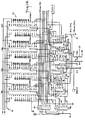
- four 16-channel analog multiplexer integrated circuits 70a, 70b, 70c and 70d are used, such as a HI-516 multiplexer circuit manufactured by the Harris Corporation. Referring to FIG. 13, the four multiplexer circuits 70a-d form a sixty-four output channel multiplexer 70.
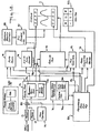
- Probes 13 (FIGS. 1 and 12) are used to pick up an input signal which is to be displayed on screen 11 of device 10. The input signal is fed by probes 13 into the input port of a signal amplifier unit 72 (FIG. 12).
- the signal amplifier unit 72 is used to amplify or attenuate the input signal to provide meaningful displays of waveforms of different amplitude.
- a manual gain control 73 can be used to adjust the gain of amplifier unit 72 and thereby the amplitude of the input signal.
- Signal amplifier unit 72 contains a programmable gain amplifier 72a and an auto-range circuit 72b which is adapted to adjust the amplitude of the input signal as a function of the potential difference which is maintained between end terminals 32 and 34 of resistor 30 (FIG. 3) and the output voltage range of the multiplexers 70a-d.
- a digital voltmeter 74 with automatic range capability which is known in the art is used to provide a visual display of the digital value of the input voltage on display 11.
- a frequency counter 75 with automatic range capability determines the frequency of the input signal which is applied to device 10. The input signal is also fed into autosync circuitry 91, the function of which is described below in connection with FIG. 14.
- the input signal is also fed into analog multiplexer 70 by feeding the input signal into line 76 which is connected to pins 2 and 28 of each of the four multiplexer circuits 70a-d (FIG. 13).
- An analog output signal is sequentially gated from each of the output terminals of each of multiplexer circuits 70a-d.
- Pins 19-26 and 4-11 on each of the multiplexer circuits 70a-d comprise the sixteen analog output terminals.
- the total of sixty-four analog output terminals for the four multiplexer circuits 70a-d are each connected to different conductive lines 20 on the inner surface 12a of plate 12.
- each of the sixty-four separate conductive lines 20 and each of the sixty-four tracks 21, or means for sequentially coupling an input voltage which is a predetermined function of the input signal at particular sample times to each second conductive element, on printed circuit board 22 (FIG. 10), which lead to the sixty-four analog output channels, is provided by means of the elastomeric connector element 23 which has been described above.
- the multiplexer control circuitry 92 (FIG. 12), or means for repetitively scanning the input voltage, is used to determine which one of the sixty-four analog output terminals will pass the input signal.
- Square wave generator 76 which includes crystal oscillator 76a and auto-time base oscillator 76b produces clock pulses for the multiplexer control circuitry 92.
- the clock pulses are inputted by line 86 to multiplexer control circuitry 92.
- the clock pulses are delivered to pin 1 of a quadruple 2-input positive AND gate, for example a SN7408 integrated circuit, which is shown as first integrated AND circuit 93 in FIG. 13.
- the input to pin 2 of AND circuit 93 is high, except when the auto sync circuitry 91 is holding up the scan at pin 2 by means of line 91a, with the result that the output of the AND gate at pin 3 of first AND circuit 93 normally matches the clock input at pin 1.
- the clock frequency controls the sweep frequency of the oscilloscope of the invention.
- This clock signal is inputted into pin 14 of first counter circuit 95, for example a SN7493 integrated circuit, which is a 4-bit binary counter.
- the binary counter outputs the binary signals A3, A 2 , A 1 , A 0 , corresponding to the number of clock pulses counted, with A3, A 29 A 1 , and A 0 corresponding to the outputs on pins 11, 8, 9 and 12 , respectively, of counter 95 .
- the signals A3, A2 , A 1 , A 0 are inputted into each of the multiplexer circuits 70a-d to select one of the sixteen available channels as the output.
- second counter circuit 96 for example a SN7493 integrated circuit
- quadruple 2 input positive NOR gate for example a SN7402 integrated circuit
- NOR circuit 97 NOR circuit 97
- hex inverter circuit 98 for example a SN7404 integrated circuit
- Second counter circuit 96 acts as a two bit binary counter, using signal A3 as the input at pin 14. Every sixteen clock pulses into first counter circuit 95 causes A3 to go high and then low, thereby increasing the count being kept by second counter circuit 96 output signals B 1 (pin 9) and B 0 (pin 12) by one. Signals B 1 and B 0 , and the complements routed through hex inverter circuit 98, are used. as inputs for four gates on NOR circuit 97.
- MUX 1 ENABLE The output signals on pins 1, 4, 10 and 13 of NOR circuit 97 are designated as MUX 1 ENABLE, MUX 2 ENABLE, MUX 3 ENABLE, and MUX 4 ENABLE, respectively.
- MUX 2 ENABLE The output signals on pins 1, 4, 10 and 13 of NOR circuit 97 are designated as MUX 1 ENABLE, MUX 2 ENABLE, MUX 3 ENABLE, and MUX 4 ENABLE, respectively.
- each of the sixty-four lines 20 of the display 20 is sequentially scanned as clock pulses are sent to the multiplexer control circuitry 92 (FIG. 12).
- each of scanned lines 20 is substantially non-resistive, so that the voltage applied through one of the output channels of multiplexer 70 connected to lines 20 appears uniformly along the length of a given scanned line 20.
- analog multiplexer 70 outputs a voltage of plus fifty volts to a scanned line 20
- the region of liquid crystal material 44 where the particular line 40 connected to resistor 30 near end terminal 32 overlaps the scanned line 20 would have no electric field applied thereto. The reason is that plus fifty volts is applied to end terminal 32.
- the voltage difference across the liquid crystal material would be 75 volts where it overlaps the scanned line 20.
- the voltage difference across the liquid crystal would be the full 100 volts.
- the portions of liquid crystal material 44 adjacent to scanned line 20, except for the region also adjacent to line 40 extending from end terminal 32 would be subjected to an electric field.
- the zero potential difference point shifts vertically with respect to display 11.
- the zero potential difference point is in the region along scanned line 20 adjacent to the horizontal line 40 that extends from location 48 on resistor 30.
- a voltage difference of 25 volts would exist at points overlapping horizontal lines 40 extending from both points 46 and 50.
- the 50 volt potential difference in the region of overlap with horizontal lines 40 connected adjacent end terminals 32 and 34 would place the liquid crystal material 44 in those regions in an opaque state.
- arrows 52 illustrate ambient light applied to display device 10
- arrows 54 represent the light reflected back through the device.
- the region 56 of liquid crystal material 44 is transparent and represents the region at which the potential on overlapping horizontal lines 40 equals the potential on vertical line 20.
- Regions 58 on either side of region 56 represent the transition between transparency and opacity, a gray scale above and below the zero potential point, and represent the region of liquid crystal material 44 where the electric field is sufficient to cause some disruption, but insufficient to render the liquid crystal material opaque.
- regions 58 might also represent areas wherein the disturbed liquid crystal material was relaxing into the transparent state, or wherein disruption was in the process of causing opacity.
- the regions 60 on either side of regions 58 represent areas wherein the potential difference between horizontal strips 40 and vertical strip 20 is sufficient to cause the liquid crystal material therebetween to be substantially opaque.
- each vertical line 20 is isolated from all other vertical lines 20, thereby effecting a built-in sample-and-hold circuit with the liquid crystal display being the capacitive component and the high impedance multiplexer 70, or means for sequentially enabling each different sample-and-hold circuit, being the resistive component.
- the analog multiplexer output signal level will change immediately with a new input signal level or on the next multiplexer scan.
- the individual vertical lines 20 can be kept isolated from the other vertical lines 20 as each one individually renders a null point somewhere along its length since an analog address technique utilizing multiplexing has been applied in scanning each channel. Since each channel is analog and contains a gray scale above and below the null point representing the transition area 58 between transparency and opacity, a minimum of multiplexer channels can be used to render a high resolution wave shape. The gray scale creates an apparent high resolution.
- the liquid crystal material 44 between plates 12 and 14 acts as a capacitor.
- the analog multiplexer 70 functions as a high impedance switch. Therefore, there is good persistence in the displayed waveforms since the capacitive and resistive effects prevent rapid discharge of the voltage level on any of the vertical lines 20.
- improved persistence can be obtained at low frequencies by actuating low frequency switch 77 in FIG. 5, thereby adding capacitors 78 across each analog output channel.
- the additional capacitance increases the time constant of the circuit and thereby the time during which each vertical line 20 can maintain a charge. ;
- An auto sync circuit 91 or means for synchronizing the scanning of the input signal, is shown in FIGS. 13 and 14.
- the auto sync circuit is based on the function of holding the sixty-four channel scan before the first channel is scanned until the proper analog input signal level is present.
- the major component is the first counter circuit 95 which counts from 0 to 15 in binary code when presented with a clock pulse at pin 14, as long as either pin 2 or 3 or both are low. For every clock pulse entering at pin 14, a binary count of 0 to 15 will be outputted as A 3 ,A 2 ,A 1 and A 0 .
- the counter starts at 0000, and with every pulse, advances forward one number. When A0 , A 1 , A2 and A3 are all high, the number is 15.
- the counter When the first counter circuit 95 reaches 15 and another pulse is introduced at pin 14, the counter resets to 0 (A 0 , A 1 , A 2 and A3 go low) and starts to count up again. If both pins 2 and 3 go high at any time during the count, the counter outputs will be reset to 0 (A 0 , A 1 , A 2 and A3 go low) and the counter will not count, even if pulses continue entering at pin 14. The counter will only resume counting when either pin 2 or 3 go low.
- pin 3 is permanently high, so that pin 2 acts as the control pin. If pin 2 goes high, the first counter circuit 95 will return to 0000 regardless of what number it has previously counted to. When pin 2 goes low, the counter starts counting from 0 to 15 and back again until pin 2 again goes high.
- the binary output of the first counter circuit 95 is also used as the input for the four multiplexer circuits 70a-d that are connected to the vertical lines 20.
- the auto sync circuit determines when multiplexer 70 is on either channel 1 or 64, and when the incoming signal matches a preset level.
- the last channel, channel 64 will be the sync time and a precision quad comparator circuit 99, for example a HA-4905 integrated circuit, will seek the sync level.
- the comparator circuit 99 and the circuitry associated therewith act as an absolute level comparator which causes signal A to go high when the incoming signal level matches the level manually set with a tunable 1 megohm potentiometer 79.
- the AND gates on the second AND integrated circuit 94 are used to indicate when the scan has reached channel 64.
- A0, A1, A2 and A3 and the MULTIPLEXER 4 ENABLE signal are high, the last channel on the last multiplexer circuit 70d is being scanned, and signal B, the output signal from the AND gate circuitry, goes high.
- Signal D forces circuit 95 to reset A 3 ,A 2 ,A 1 and A 0 to 0000, and forces circuit 96 to reset B 1 and B 0 so that the MUX 4 ENABLE signal goes to 0.
- the resetting of A 3 ,A 2 ,A 1 ,A 0 forces signal B to go low, thereby enabling the AND gate which allows clock pulses to pass to pin 14 of first counter circuit 95.
- the reset of circuit 95 also forces signal D to go low, thereby removing the reset signal from pin 2 of both counter circuit 95 and 96. This allows the counters to count to sixty-four again so that the vertical lines 20 can be sequentially scanned.
- FIG. 2 Another feature of the invention is a vertical cursor that can be moved horizontally across the display 11 on display device 10, as shown in FIG. 2.
- Device 10 has a keypad 83 (FIG. 12) with keys which can be used to manually enter instructions into processor 85. Certain keys, or means for preselecting one second conductive element, are pressed to turn the cursor feature on and off and to move the cursor left or right.
- the processor 85 or means for providing a cursor in a predetermined location, stores a number representing which one of the sixty-four channels, corresponding to each of the vertical lines 20, the operator has chosen as the cursor channel.
- the processor is able to determine which output channel is being scanned at any time by retrieving the values of A 3' A 2 , A 1 and A 0 from the first counter circuit 95, and by retrieving the values of B 1 and B 0 from pins 9 and 12, respectively, of second counter circuit 96.
- the processor 85 will prevent the display from operating by disabling cursor switch 86, or means for interrupting the scanning of the input voltage to the preselected element, which is connected between signal amplifier 72 and the inputs into analog multiplexer 70.
- cursor switch 86 will result in the display 11 being dark along the vertical path of scanned line 20 at the location where a portion of the waveform would otherwise have been displayed. Instead, the voltage on the preselected second conductive element 20 will rapidly decay to zero, so that a spot indicating the zero potential difference point is in the region along preselected element 20 adjacent to the horizontal line 40 that extends from location 48 on resistor 30. (Fig. 3).
- the display 11 can alternatively be made dark along the entire vertical path of preselected element 20 by having cursor switch 86, or means for placing a fixed voltage on the preselected element, connected to a second input from a fixed voltage source that exceeds +50 or -50 volts.
- the processor 85 causes the cursor switch 86 to switch to the second input when the cursor channel is being scanned. This places a voltage unequal to any of the voltages on the horizontal lines 40 connected to resistor 30 onto the preselected element 20.
- the difference in voltages between the preselected element 20 and all of the horizontal lines 40 causes the display to be black along the entire vertical path of the preselected element 20, thereby displaying a black vertical cursor line that moves when a different cursor channel is selected.
- the processor 85 will send a pulse to digital voltmeter 74, or means for sampling the voltage level at the time of scanning the preselected element, when the cursor channel is being scanned.
- This pulse will cause the digital voltmeter to sample-and-hold the instantaneous voltage of the input signal as the cursor channel is scanned. In this way, the voltage level of the waveform where it would have otherwise intersected the vertical line 20 on the display can be displayed in digital form on device 10, or means for indicating the voltage level of the input signal.
- FIG. 2 Another embodiment of the cursor feature shown in Fig. 2 requires the placing of fixed indicia 100 on plate 12 or plate 14, preferably the plate closest to the viewer.
- the fixed indicia 100 can be etched, painted, or adhered to the plate and principally consists of an easily visible vertical line that exactly overlays one of the vertical lines 20. For viewing convenience, it is preferable to overlay a vertical line 20 near the center of the display, e.g., no. 33, and have it serve as the preselected element.
- the fixed indicia 100 functions as the cursor line and there is no need to use a cursor switch 86. Different portions of the waveform can be intersected by the cursor line by manually adjusting the tunable 1 megohm potentiometer 79.
- FIG. 14 The scanning of the input signal is delayed by the auto sync circuit 91 until the incoming signal matches the preset level, so that the waveform can be horizontally shifted on the display as tunable potentiometer 79 is adjusted.
- the instantaneous voltage of the input signal where it intersects the vertical cursor line (Fig. 2) is displayed by digital voltmeter 74 as described above, with the processor 85 sending a pulse at the time of scanning of the particular preselected element 20 that is overlayed by the fixed indicia 100.
- a voltage is placed across resistor 30 in FIGS. 3 and 12 by means, for example, of a +50 volt power supply 87.
- vertical position control 88 the operator can manually adjust the voltages applied across resistor 30 at end terminals 32 and 34 and thereby vertically adjust the zero voltage position on the display 11 on device 10.
- the display 11 is also able to trace two separate waveforms obtained from input signals connected to two different probes 13, or means for receiving the electrical input signal and a second electrical input signal.
- a dual trace switch 89 or means for sequentially and alternatly introducing one of the input signals to the sequentially coupling means, is connected to both probes 13 and has a single output to signal amplifier 72.
- the processor 85 When the operator uses the keypad 83 to manually indicate that a dual trace is desired, the processor 85 will look at signal A 0 from first counter circuit chip 95 which switches high or low with every clock pulse. As signal A 0 changes, processor ' 85 will send a signal to dual trace switch 89 which causes it to switch back and forth between the two input probes 13. As a result, the odd-numbered vertical lines 20 will display a waveform different from that of the even-numbered vertical lines 20 when scanned.
- Signal amplifier 72 contains a programmable gain amplifier, or means for adjusting the input voltages applied by the introducing means, which will look at signal A when in the dual trace mode and separate the horizontal center lines on the display 11 for the two waveforms.
- the first input signal may be processed so as to use the horizontal line 40 extending from location 50 (FIG. 3) along resistor 30 as its horizontal center line, whereas the second input signal may instead use the horizontal line 40 extending from location 46 as its horizontal center line. In this manner, a display with a dual trace is obtained.
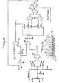
- An alternative embodiment of the invention utilizes an inductor 98 in place of analog multiplexer 70 as shown in FIG. 15.
- the input signal is routed into the inductor 101 by an output line from signal amplifier 72 which is connected to one end of the inductor.
- the inductor 101 has sixty-four taps 102 which are each connected to different conductive lines 20 on the' inner surface 12a of plate 12. At high frequencies the inductor! 101 acts like a delay line, so that the voltage level at each of the taps 102 is equivalent to the voltage level of the input signal at different sample times.
- the liquid crystal display acts as a series of capacitive components that allow circuits involving each of the taps 102 to be completed. In order to obtain a meaningful display, the inductor 101 must be tunable.
- a standing waveform is obtained along the length of inductor 101 by tuning the inductor 101 so that the frequency of the input signal is an integer multiple of the resonant frequency associated with the tuned inductor.
- the response time and other characteristics of the liquid crystal material 44 between the vertical lines 20 connected to each tap 102 and the inner surface 14a on the opposite plate 14 are such that the effective potential difference across each vertical section of the liquid crystal 44 will be proportional to the rms voltage present at each tap 102 along inductor 101.
- the null points rendered along the lengths of adjacent vertical lines 20 will represent the input signal voltage levels at a series of discrete consecutive times, and will remain stable if the inductor 101 is properly tuned and the frequency of the input signal does not vary.
- the term "transmission" 1 embodies each of the following methods of displaying waveforms: (1) a transmissive liquid crystal material, which is either transparent or opaque, is used and either (a) the viewer and light source (artificial or ambient) are on opposite sides of the viewing screen, or (b) the viewer and light source are on the same side of the viewing screen, with one of the surfaces on the plate farthest from the viewer being reflective; (2) a reflective liquid crystal material, which is either reflective or light absorbing, is used and the viewer and light source are on the same side of the viewing screen; (3) a transflective liquid crystal material, which is either transparent or reflective, is used and either (a) the viewer and light source are on opposite sides of the screen, or (b) the viewer and light source are on the same side of the viewing screen, with one of the surfaces on the plate farthest from the viewer being light absorbing; and (4) a light emitting material,
- the presence of an electric field can cause the material to exhibit either one of the two optical properties possible for that type (e.g., transmissive, reflective, transflective) of liquid crystal material.
- an electric field can cause the material to exhibit either one of the two optical properties possible for that type (e.g., transmissive, reflective, transflective) of liquid crystal material.
Landscapes
- Physics & Mathematics (AREA)
- General Physics & Mathematics (AREA)
- Nonlinear Science (AREA)
- Mathematical Physics (AREA)
- Chemical & Material Sciences (AREA)
- Crystallography & Structural Chemistry (AREA)
- Optics & Photonics (AREA)
- Control Of Indicators Other Than Cathode Ray Tubes (AREA)
- Liquid Crystal Display Device Control (AREA)
- Liquid Crystal (AREA)
Applications Claiming Priority (2)
| Application Number | Priority Date | Filing Date | Title |
|---|---|---|---|
| US656972 | 1984-10-02 | ||
| US06/656,972 US4690509A (en) | 1984-10-02 | 1984-10-02 | Waveforms on a liquid crystal display |
Publications (2)
| Publication Number | Publication Date |
|---|---|
| EP0177331A2 true EP0177331A2 (de) | 1986-04-09 |
| EP0177331A3 EP0177331A3 (de) | 1986-10-29 |
Family
ID=24635338
Family Applications (1)
| Application Number | Title | Priority Date | Filing Date |
|---|---|---|---|
| EP85307010A Withdrawn EP0177331A3 (de) | 1984-10-02 | 1985-10-01 | Verfahren und Vorrichtung zum Darstellen von Wellenformen auf einer Flüssigkristallsichtanzeige |
Country Status (4)
| Country | Link |
|---|---|
| US (1) | US4690509A (de) |
| EP (1) | EP0177331A3 (de) |
| JP (1) | JPS61198132A (de) |
| CA (1) | CA1249678A (de) |
Families Citing this family (6)
| Publication number | Priority date | Publication date | Assignee | Title |
|---|---|---|---|---|
| US4862387A (en) * | 1985-01-11 | 1989-08-29 | Lee Arnold S J | Universal-gain data plotter |
| US4937037A (en) * | 1985-08-06 | 1990-06-26 | Christopher A. Griffiths | Combined inforamtion recording and graphic display device |
| US5033824A (en) * | 1990-08-02 | 1991-07-23 | Display Matrix Corporation | Convertible analog-digital mode display device |
| TW594338B (en) * | 2003-02-14 | 2004-06-21 | Quanta Display Inc | A two TFT pixel structure liquid crystal display |
| KR101740672B1 (ko) * | 2010-03-05 | 2017-05-29 | 삼성디스플레이 주식회사 | 표시패널 |
| USD754554S1 (en) * | 2015-01-02 | 2016-04-26 | Fluke Corporation | Hand held scope meter |
Family Cites Families (12)
| Publication number | Priority date | Publication date | Assignee | Title |
|---|---|---|---|---|
| US3322485A (en) * | 1962-11-09 | 1967-05-30 | Rca Corp | Electro-optical elements utilizing an organic nematic compound |
| US3820875A (en) * | 1972-04-14 | 1974-06-28 | W Bohmer | Scanner devices utilizing field effect light scattering dielectrics |
| US3807831A (en) * | 1972-06-20 | 1974-04-30 | Beckman Instruments Inc | Liquid crystal display apparatus |
| US3834794A (en) * | 1973-06-28 | 1974-09-10 | Beckman Instruments Inc | Liquid crystal electric field sensing measurement and display device |
| GB1559074A (en) * | 1975-11-05 | 1980-01-16 | Nat Res Dev | Electonic analogues waveform displays |
| GB2001794B (en) * | 1977-07-26 | 1982-01-27 | Secr Defence | Method of and apparatus for displaying waveforms |
| NL7809081A (nl) * | 1978-09-06 | 1980-03-10 | Philips Nv | Matrix-stuurschakeling voor een oscilloscoopweergeef- scherm met een vloeibaar kristal. |
| US4346378A (en) * | 1979-05-03 | 1982-08-24 | National Research Development Corporation | Double trace electro optic display |
| US4392129A (en) * | 1979-07-02 | 1983-07-05 | Solid State Systems, Inc. | Multiplexed liquid crystal display |
| JPS57500848A (de) * | 1980-06-27 | 1982-05-13 | ||
| DE3122558A1 (de) * | 1981-06-06 | 1983-02-10 | Metrawatt GmbH, 8500 Nürnberg | Digitales messgeraet mit fluessigkristall-bildschirm |
| JPS5934587A (ja) * | 1982-08-23 | 1984-02-24 | 株式会社日立製作所 | 液晶装置 |
-
1984
- 1984-10-02 US US06/656,972 patent/US4690509A/en not_active Expired - Fee Related
-
1985
- 1985-10-01 EP EP85307010A patent/EP0177331A3/de not_active Withdrawn
- 1985-10-02 JP JP60219963A patent/JPS61198132A/ja active Pending
- 1985-10-02 CA CA000492107A patent/CA1249678A/en not_active Expired
Also Published As
| Publication number | Publication date |
|---|---|
| US4690509A (en) | 1987-09-01 |
| CA1249678A (en) | 1989-01-31 |
| JPS61198132A (ja) | 1986-09-02 |
| EP0177331A3 (de) | 1986-10-29 |
Similar Documents
| Publication | Publication Date | Title |
|---|---|---|
| US4529271A (en) | Matrix addressed bistable liquid crystal display | |
| US3899786A (en) | Liquid crystal color display system | |
| US4127848A (en) | Liquid crystal waveform displays | |
| EP0588568A2 (de) | Flüssigkristall-Anzeigevorrichtung | |
| EP0185495A2 (de) | Flüssigkristallanzeigetafel | |
| KR20000068600A (ko) | 디스플레이 장치 | |
| KR960008099B1 (ko) | 매트릭스 디스플레이 장치 | |
| US3674342A (en) | Liquid crystal display device including side-by-side electrodes on a common substrate | |
| US4449125A (en) | Matrix display device | |
| US4690509A (en) | Waveforms on a liquid crystal display | |
| EP0000422B1 (de) | Kathodenstahlröhre, die einen Schirm mit einer elktrooptischen Substanz verwendet | |
| KR19990014878A (ko) | 플라즈마-어드레스 디스플레이 | |
| US4641923A (en) | Field sensitive optical displays with electrodes with high and low impedance portions | |
| US5029983A (en) | Liquid crystal device with a smectic chiral liquid crystal | |
| EP0175417A1 (de) | Flüssigkristallanzeigeeinrichtung | |
| EP0224388A2 (de) | Flüssigkristallanzeigevorrichtung mit aktiver Matrix | |
| US4116543A (en) | Control electro-optical device utilizing liquid crystal | |
| US4585311A (en) | Liquid crystal device having interdigitated electrodes | |
| CN112099276A (zh) | 驱动阵列基板、显示面板和显示设备 | |
| EP0416597A2 (de) | Flüssigkristall Anzeigevorrichtung | |
| US4109242A (en) | Matrix address system using erase operation | |
| US6233028B1 (en) | Plasma-addressed liquid crystal display with reduced column voltages | |
| CA1174388A (en) | Dual trace electro-optic display | |
| US5903325A (en) | Plasma addressed liquid crystal display panel with optimized relationship between liquid crystal parameters and cover sheet thickness | |
| EP0044637B1 (de) | Feldstärkeabhängige optische Anzeigen, Erzeugung der elektrischen Felder und Abtastung der Anzeigen |
Legal Events
| Date | Code | Title | Description |
|---|---|---|---|
| PUAI | Public reference made under article 153(3) epc to a published international application that has entered the european phase |
Free format text: ORIGINAL CODE: 0009012 |
|
| AK | Designated contracting states |
Kind code of ref document: A2 Designated state(s): DE FR GB IT NL |
|
| PUAL | Search report despatched |
Free format text: ORIGINAL CODE: 0009013 |
|
| AK | Designated contracting states |
Kind code of ref document: A3 Designated state(s): DE FR GB IT NL |
|
| 17P | Request for examination filed |
Effective date: 19870423 |
|
| RAP1 | Party data changed (applicant data changed or rights of an application transferred) |
Owner name: CONTROL INTERFACE CORPORATION |
|
| 17Q | First examination report despatched |
Effective date: 19890426 |
|
| STAA | Information on the status of an ep patent application or granted ep patent |
Free format text: STATUS: THE APPLICATION IS DEEMED TO BE WITHDRAWN |
|
| 18D | Application deemed to be withdrawn |
Effective date: 19900109 |
|
| RIN1 | Information on inventor provided before grant (corrected) |
Inventor name: BOHMER, WILLIAM |