EP0176889A2 - Verfahren zur Messung des Orientierungsgrades oder dielektrischer Eigenschaften von dielektrischen Schichten oder Bändern - Google Patents
Verfahren zur Messung des Orientierungsgrades oder dielektrischer Eigenschaften von dielektrischen Schichten oder Bändern Download PDFInfo
- Publication number
- EP0176889A2 EP0176889A2 EP85111934A EP85111934A EP0176889A2 EP 0176889 A2 EP0176889 A2 EP 0176889A2 EP 85111934 A EP85111934 A EP 85111934A EP 85111934 A EP85111934 A EP 85111934A EP 0176889 A2 EP0176889 A2 EP 0176889A2
- Authority
- EP
- European Patent Office
- Prior art keywords
- sheet
- sample portion
- dielectric
- waveguides
- sample
- Prior art date
- Legal status (The legal status is an assumption and is not a legal conclusion. Google has not performed a legal analysis and makes no representation as to the accuracy of the status listed.)
- Ceased
Links
Images


Classifications
-
- G—PHYSICS
- G01—MEASURING; TESTING
- G01R—MEASURING ELECTRIC VARIABLES; MEASURING MAGNETIC VARIABLES
- G01R27/00—Arrangements for measuring resistance, reactance, impedance, or electric characteristics derived therefrom
- G01R27/02—Measuring real or complex resistance, reactance, impedance, or other two-pole characteristics derived therefrom, e.g. time constant
- G01R27/26—Measuring inductance or capacitance; Measuring quality factor, e.g. by using the resonance method; Measuring loss factor; Measuring dielectric constants ; Measuring impedance or related variables
- G01R27/2617—Measuring dielectric properties, e.g. constants
- G01R27/2635—Sample holders, electrodes or excitation arrangements, e.g. sensors or measuring cells
- G01R27/2658—Cavities, resonators, free space arrangements, reflexion or interference arrangements
- G01R27/2664—Transmission line, wave guide (closed or open-ended) or strip - or microstrip line arrangements
-
- G—PHYSICS
- G01—MEASURING; TESTING
- G01N—INVESTIGATING OR ANALYSING MATERIALS BY DETERMINING THEIR CHEMICAL OR PHYSICAL PROPERTIES
- G01N22/00—Investigating or analysing materials by the use of microwaves or radio waves, i.e. electromagnetic waves with a wavelength of one millimetre or more
Definitions
- the present invention relates to a method of measuring the molecular orientation or dielectric characteristic of a dielectric sheet or web in a very simple manner and in a short time.
- the dielectric sheet is a paper sheet
- the viscosity force of paper stock developed when the stock is spouted at high speed from the head box or the dragging force exerted on the paper stock by the wire cloth, on which it is carried, traveling at a speed almost equal to the flow rate of stock causes the fibers to be oriented in the direction of flow, thus producing differences in paper strength and gloss between longitudinal and transverse directions.
- a sample of paper is taken at the reel part of the paper making machine as soon as the paper roll is wound up and the sample is tested as by measurement of zero-span tensile strength method (TAPPI, STD, T481 sm-60), ultra-sonic method, X-ray diffraction method, or viscoelasticity spectroanalysis.
- TAPPI zero-span tensile strength method
- STD reel part of the paper making machine
- T481 sm-60 ultra-sonic method
- X-ray diffraction method or viscoelasticity spectroanalysis.
- Such methods involve a troublesome procedure for setting a sample strip such as a sheet or a sample protion in the measuring mechanism and takes a long time in ascertaining the abnormality of fiber orientation.
- a large amount of reject would be produced before the completion of a checkup of fiber orientation over the entire width of the machine, particularly a modern machine which has been sped up and increased in width.
- a non-stretched sheet is produced either by the tubular film process in which the sheet material is first heated or friction-melted to be given fluidity and then extruded into a cylindrical form, into which air is blown to inflate it and at the same time it is externally cooled for solidification or by the T-die process in which the melt is extruded into a smooth thin film form and then cooled for solidification in a water tank or on a cooling drum.
- such non-stretched sheet is too inferior in such mechanical strengths as tensile strength, impact strength and tear strength and in processability to be used as such.
- the non-stretched sheet is heated to a suitable temperature above its softening point but below its melting point and subjected to uniaxial or biaxial stretching to improve its physical properties.
- uniaxial or biaxial stretching it does not necessarily follow that simply mechanically stretching the non-stretched sheet provides a sheet of good quality, but it is necessary that the stretching be performed to provide a particular orientation of molecules to agree with the intended use of the sheet product.
- a fine ceramic powder is mixed with a binding agent and a lubricant to produce a slip, which is then poured onto a continuously traveling tape of polyethylene or Teflon, and after the thickness of the slip layer on the tape is adjusted as by a doctor, it is fired and finished, the process being called the tape casting forming method, whereby a ceramic sheet in thin film form is obtained.
- Such thin film-like ceramic sheets are used as a material for laminated ceramic capacitors, for example, by laminating them alternately with electrodes.
- ceramic sheets it is of utmost importance from the standpoint of securing the quality of capacitors at high level that the dielectric constant across the width of ceramic sheets be substantially uniform. Therefore, a checkup of widthwise molecular orientation corresponding to dielectric constant must be made so that only those ceramic sheets which are appropriate may be used. Therefore, said plastic films and ceramic films must be tested for their molecular orientation as in the case of fiber sheets.
- dielectric characteristic which is one of the electrical characteristics of dielectric sheets such as those described above
- dielectric characteristics As a result of the increasing use of high frequency waves in the electrical communications field it has become very important, in selecting IC boards or dielectric materials for high frequency cables, to know their dielectric characteristics. Therefore, in the industry there has been a demand for establishing a measuring method which is simple and yet relatively accurate.
- An object of the invention is to provide a method of measuring the molecular orientation or dielectric characteristic of a dielectric sheet in a very simple manner and in a short time.
- the invention provides a method of measuring the orientation or dielectric characteristic of a dielectric sheet or web, characterized by inserting a sample portion of the dielectric sheet or web in a small clearance in a cavity resonator formed of a pair of waveguides respectively having a transmitting antenna and a receiving antenna, said waveguides being spaced apart from each other with their openings defining said clearance therebetween, irradiating said sample portion with frequency sweep type linearly polarized microwaves from the upper waveguide perpendicularly to said sample portion while producing a relative motion between the plane of polarization of microwaves and said sample portion around the axis of said cavity resonator, and measuring the resonance frequency or Q value of the microwaves received by the lower waveguide.
- Equation (2) C 1 and C 2 in equation (2) are expressed by equations (3) and (4)
- the dielectric constant is given by equation (6).
- N is the number of dipoles per unit volume
- ⁇ is the effective dipole moment
- C 3 and C 4 are constants.
- Equation (8) Let.l be the length of a rectangular waveguide.
- Q be the Q value of the cavity resonator where there is a sheet
- Q o be the Q value of the cavity resonator system where there is no sheet
- ⁇ 2 and. ⁇ 2 " in equation (8) can be approximated as indicated by equations (9) and (10).
- f o and Q 0 are found beforehand and values of f and Q for each angle are measured, then ⁇ 2 and can be found by computation.
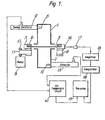
- Fig. 1 schematically shows an embodiment of an apparatus used for the method of measuring the molecular orientation and dielectric characteristic of a sheet according to the invention.
- the numeral 4 denotes a sweep oscillator which emits linearly polarized sawtooth waves (5 Hz sweep) in the range of 4.9 - 5. 0 GHz, for example.
- the microwaves are emitted from a transmitting antenna 5 so that they fall on the surface of a sheet 3 always at right angles thereto.
- microwaves which are usable are inJ:he range of hundreds of MHz to 100 GHz, but since attenuation due:to rearrangement of the molecules of sheets takes place more readily at frequencies of less than 1 GHz, it is more preferable to use microwaves of about 1 - 30 GHz.
- sheets that can be measured mention may be made of fiber sheets such as paper sheets, plastic sheets such as are made of polyethylene, polyoxymethylene, polyvinyl chloride, polyvinylidene fluoride, polyethylene terephthalate, polyamides, polyimides or copolymers of their and other polymers, ceramic sheets such as are made of alumina, alumina silicate, barium titanate, titanium oxide, silicon carbide, strontium titanate, carbon sheets, carbon fiber-containing plastic sheets living membrane sheets, ionic equilibrium membrane sheets, and cellular sheets encapsulating a material such as high molecular liquid crystal, polymer solvent, colloidal solvent, gel materials, or short filament dispersing fluid.
- plastic sheets such as are made of polyethylene, polyoxymethylene, polyvinyl chloride, polyvinylidene fluoride, polyethylene terephthalate, polyamides, polyimides or copolymers of their and other polymers
- ceramic sheets such as are made of alumina, alumina silicate, barium titanate,
- a drive belt 11 is entrained in a belt drive groove 8 formed in the lateral lower portion of the sheet fixing block 7 and in a groove in a drive pulley 10 on the front end of a variable speed motor 9 and the latter is driven.
- a stepping motor may be used as said variable speed motor.
- the linearly polarized microwaves attenuated by the molecules in the sheet 3 are received by a receiving antenna 12 after they have passed through the lower waveguide 2, and they are converted into electric signals. Such electric signals are demodulated by a detector 13 and then fed to a differentiating and comparing circuit 14. Since the resonance frequency in this case is the frequency at which the detected output obtained during sweep is at a maximum, the frequency for which the differentiated value from the differentiating and comparing circuit 14 is zero is taken as the resonance frequency.
- the resonance frequency obtained is recorded by a recorder 15.
- the resonance frequency curve recorded on the chart in the recorder is as shown in Fig. 2.
- a narrow reflecting tape 16 is applied to only one place on the lateral surface of the sheet fixing block 7 so that variations in reflectance of monitor light are detected during rotation by an optical sensor 17 and the resulting electric signals are transferred via an amplifier 18 and a comparator 19 to the recorder 15, whereby they are recorded on the chart as shown at Y in Fig. 2.
- the sheet 3 when attached to the sheet fixing block 7, is positioned so that for example the upstream side of the longitudinal direction is the direction of the reflecting tape 16.
- FIG. 3 An embodiment shown in Fig. 3 is the same as that shown in Fig. 1 in that the sheet 3 is fixed on the sheet fixing block 7 by the keep ring plate 6 and is held between the upper and lower waveguides 1 and 2, but it differs in that the waveguides 1 and 2 can be rotated while the sheet 3 is kept without being rotated.
- the synchronous rotation of the upper and lower waveguides 1 and 2 is achieved, as shown in Fig. 3, by connecting a reversible motor 20 for the waveguides, a drive shaft 21, and waveguide main shafts 22 and 23 by means of belts.
- the angle of rotation for the waveguides be set at a value greater than the angle of 180 0 needed for measurement, and the initial waiting angle and the next waiting angle can be defined by installing optical sensors, limit switches or the like for detecting the angles, at suitable positions.
- Fig. 3 shows the method of rotating the waveguides by using pulleys and belts, depending upon the objective there may be employed a method of directly rotating the plane of linear polarization as by connecting separate electric motors directly to the ends of the waveguides or applying a magnetic field to the upper waveguide.
- the linearly polarized microwaves passing through the sheet 3 in the cavity resonator system, after passing through the lower waveguide 2, are received by the receiving antenna 12 and then converted into electric signals. Such electric signals are demodulated by a detector 13 and transferred to a control section 24.
- narrow reflecting tapes 25 and 26 are applied, 180 0 apart, to two places on the lateral surface of the upper waveguide 1 so that variations in reflectance of monitor light are detected during rotation by an optical sensor 17 and the resulting electric signals are transferred via an amplifier 18 and a comparator 19 to a control section 24.
- the sheet 3 when attached to the sheet fixing block 7, is positioned so that for example the upstream side of the longitudinal direction is the direction of the reflecting tape 25.
- the signal from the reflecting tape 25 is transferred from the optical sensor 17, it always indicates the upstream side of the longitudinal direction, so that such angle can be used as the reference angle.
- Measurement is started when a measurement start signal enters the control section 24.
- the control section 24 on the basis of a program inputted thereinto in advance, emits a forward rotation start signal to the reversible motor 20, so that the two waveguides 1 and 2 start rotating in the forward direction from the initial wating angle.
- the control section 24 soon receives from the optical sensor 17 a signal indicating that the reflecting tape 25 has passed by, and it stores this signal as the measurement start angle and thereafter it also receives a signal notifying the passage of the reflecting tape 26 and stores this signal as the measurement termination angle and emits an operating stop signal to the reversible motor 20, stopping the waveguides 1 and 2 at the next waiting angle.
- the control section 24 computes the received resonance frequency values corresponding to the individual angles of rotation inputted thereinto from the detector 13 during the interval from measurement start angle to measurement stop angle, and according to the need it delivers its output to a display section 27 such as a CRT or an X - Y plotter.
- the sample on the sheet fixing block 7 is exchanged and a measurement start signal 28 is inputted again.
- the control section 24 gives a reverse rotation command to the reversible motor 20, causing the waveguides 1 and 2 to follow the course which is reverse to the previous one, so that the waveguides 1 and 2 are brought back to the initial waiting angle. Thereafter, the aforesaid procedure is repeated a predetermined number of times. In addition, the same computing operation is performed and the result is outputted to the display section 27.
- Fig. 4 shows an embodiment of the invention wherein to observe two-dimensional molecular orientation characteristics of of sheets, a narrow sample is taken in the flow direction or width direction from the sheet roll wound up at the reel part and the apparatus of the invention is applied to such sample.
- the polarization plane rotating mechanism and the detecting means using an optical sensor are the same as those shown in Fig. 3.
- a sheet roll 29 of narrow sample is unwound from an unillustrated reel stand and passed over a guide roll 30 and through the nip of sheet feed rolls 31.
- Such sheet feed nip rolls 31 are driven by a variable speed motor 9. Further, its operation and stoppage are optionally set by signals from the control section 24.
- the operative speed of the reversible motor 20 is set to rotate the waveguides 1 and 2 at a required rotative speed, while the amount of rotation and measurement-intended stop time of the sheet feed motor 9 are set to feed the sheet 3 at a required speed.
- the reflecting tape 25 for the waveguide 1 is set at the initial waiting angle, while the transmitting antenna 5 is emitting linearly polarized waves.
- a measurement start signal 28 is sent to the control section 24, the latter emits an operation start signal to the sheet feed motor 9 on the basis of the program inputted thereinto in advance, and when the first measuring place reaches the middle between the waveguides 1 and 2, the control section emits an operation stop signal to the sheet feed motor 9 and at the same time it emits a forward rotation start signal to the reversible motor 20, which thereby rotates the waveguides 1 and 2 in the forward direction from the initial waiting angle.
- the optical sensor 17 passes by the reflecting tape 26, a forward rotation stop signal is emitted to the reversible motor 20, and the waveguides are stopped at the next waiting angle.
- the control section 24 stores or memorizes as the first-time measured values the resonance frequencies corresponding to the individual angles 180° from the resonance frequencies received by the receiving antenna 12.
- the control section 24 again operates the sheet feed motor 9 to feed the sheet 3 until its second-time measurement place stops and at the middle between the waveguides 1 and 2, while emitting a backward rotation start signal to the reversible motor 20.
- the waveguides 1 and 2 are reversely rotated from the waiting angle and the resonanQe frequencies corresponding to the individual angles in 180° are stored as the second-time measured measured values.
- the same procedure as the above are repeated and the results are computed and outputted to a display section 27 such as a printer, an X - Y plotter or the like.
- a display section 27 such as a printer, an X - Y plotter or the like.
- cavity resonators applicable to the present invention, those whose Q values as measured with a sheet put in are not less than at least several hundreds are preferable, since the higher the Q value, the greater the frequency deviation and the more distinct is anisotropy reflected.
- a sample of wood free paper having a reel air-dry weight of 45 g/m 2 and a reel moisture content of 7% from a Fourdrinier machine operating at a running speed of 450 m/min was measured by a molecular orientation or dielectric characteristic measuring apparatus of the arrangement shown in Fig. 1 used in the method of the invention.
- the upstream side of longitudinal direction of said sample was made the direction of the reflecting tape 16 and then while rotating the waveguides 1 and 2 1.
- the sample was measured using linearly polarized sawtooth waves of 3.4 - 3.5 GHz (5 Hz sweep), whereby a graph was obtained as shown in Fig. 5 wherein the amounts of deviation corresponding to the individual angles are indicated by distances from the origin.
- the fiber orientation was in the longitudinal direction.
- the present method was compared with the method based on zero-span tensile strength measurement.
- the result obtained by the conventional zero-span tensile strength method is shown in Fig. 6.
- the direction in which the deviation was at a maximum significantly corresponded to the direction in which the tensile strength was at a maximum.
- the time needed from the time the sample was obtained until the completion of the determination of orientation was about 2 minutes in the present invention, whereas in the zero-span tensile strength method it was about 18 0 minutes or more.
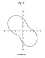
- a 70- ⁇ m thick polyethylene terephthalate sample obtained by stretching with a tenter-method biaxial stretching apparatus was measured by a molecular orientation or dielectric characteristic measuring apparatus constructed in the manner shown in Fig. 1 used in the present invention.
- the waveguides 1 and 2 used were in the form of a rectangle with an opening size of 58. 1 mm x 29. 1 mm.
- the upstream side of longitudinal direction of said sample was made the direction of the reflecting tape 16 and then the sample was measured using linearly polarized sawtooth waves of 4. 9 - 5.0 GHz (5 Hz sweep) while rotating it at 1. 0 rpm.
- a graph was obtained as shown in Fig. 7 wherein the amounts of deviation corresponding to the individual angles are indicated by distances from the origin.
- a 5-m wide polyethylene terephthalate sheet obtained under the same conditions as in Example 2 was slitted along the direction of flow into 10 equal strips to provide narrow samples. Such samples were measured by a molecular orientation dielectric characteristic measuring apparatus constructed in the same manner as shown in Fig. 4. A feed rate of 200 mm/pitch, a stop time of 1 second, and a rotative speed of the reversible motor 20 to provide a waveguide rotative speed of 1. 0 rpm were set in the control section 24. The amounts of deviation corresponding to the individual angles of the narrow samples were obtained by optionally selecting 10 deviation values for the same angle measured in the direction of flow and averaging them; the chart indicating the output from the X - Y recorder was shown in Fig. 8.
- a 100- ⁇ m thick alumina silicate sample obtained by the tape casting forming method was measured by the apparatus of the invention constructed in the manner shown in Fig. 3.
- Waveguides 1 and 2 having the same size and shape as those used in Example 1 were used, and the upstream side of longitudinal direction of said sample was made the direction of the reflecting tape 25 and then the sample was measured using linearly polarized sawtooth waves of 3.4 - 3.5 GHz (5 Hz sweep) while rotating the waveguides 1 and 2 at a rotative speed of 1. 0 rpm.
- a graph as shown in Fig. 9 was obtained in which the amounts of deviation corresponding to the individual angles are indicated by distances from the origin.
- the direction in which the deviation is at a maximum coincides with the upward or downward direction, in the sample in this example it was readily ascertained that the molecular orientation is in the longitudinal direction.
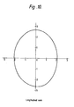
- a 50- ⁇ m thick polyoxymethylene sample obtained by stretching to twice the longth with a uniaxial stretching apparatus was measured with waveguides having the same shape as in Example 2 using linearly polarized sawtooth waves of 3.43 - 3. 48 GHz (5 Hz sweep) while rotating the sample intermittently in steps of 15° by a stepping motor.
- Graphs were obtained as shown in Figs. 10 and 11 wherein dielectric constants and dielectric loss factors corresponding to the individual angles are indicated by distances from the origin.
- degrees of dependency of f, 2 and ⁇ 2 ' on angle are approximately equal. Further, the time needed for measurement after the sample was obtained was 3 minutes.
- a checkup of the molecular orientation or dielectric characteristic of sheets can be made extremely easily and in a short time, making it possible to cope with abnormality during its early stage, so that the occurrence of rejects can be kept to a minimum.
Landscapes
- Physics & Mathematics (AREA)
- General Physics & Mathematics (AREA)
- Electromagnetism (AREA)
- Health & Medical Sciences (AREA)
- Life Sciences & Earth Sciences (AREA)
- Chemical & Material Sciences (AREA)
- Analytical Chemistry (AREA)
- Biochemistry (AREA)
- General Health & Medical Sciences (AREA)
- Immunology (AREA)
- Pathology (AREA)
- Measurement Of Resistance Or Impedance (AREA)
Applications Claiming Priority (2)
| Application Number | Priority Date | Filing Date | Title |
|---|---|---|---|
| JP199225/84 | 1984-09-22 | ||
| JP59199225A JPS6176942A (ja) | 1984-09-22 | 1984-09-22 | 誘電体シートの配向性又は誘電特性の測定方法 |
Publications (2)
| Publication Number | Publication Date |
|---|---|
| EP0176889A2 true EP0176889A2 (de) | 1986-04-09 |
| EP0176889A3 EP0176889A3 (de) | 1989-02-01 |
Family
ID=16404224
Family Applications (1)
| Application Number | Title | Priority Date | Filing Date |
|---|---|---|---|
| EP85111934A Ceased EP0176889A3 (de) | 1984-09-22 | 1985-09-20 | Verfahren zur Messung des Orientierungsgrades oder dielektrischer Eigenschaften von dielektrischen Schichten oder Bändern |
Country Status (4)
| Country | Link |
|---|---|
| US (1) | US4710700A (de) |
| EP (1) | EP0176889A3 (de) |
| JP (1) | JPS6176942A (de) |
| FI (1) | FI853638L (de) |
Cited By (7)
| Publication number | Priority date | Publication date | Assignee | Title |
|---|---|---|---|---|
| EP0240610A2 (de) * | 1986-01-08 | 1987-10-14 | Hercules Incorporated | Apparat und Methode zur Bestimmung mehrerer Parameter von flächenhaftem Material |
| GB2211299A (en) * | 1987-10-19 | 1989-06-28 | De Beers Ind Diamond | Sorting particulate material on the basis of size or composition |
| GB2214310A (en) * | 1988-01-22 | 1989-08-31 | Atomic Energy Authority Uk | Material characterisation using a microwave device |
| US4943778A (en) * | 1987-12-21 | 1990-07-24 | Kanzaki Paper Manufacturing Co., Ltd. | Instrument for measuring high frequency characteristics of sheet-like materials |
| GB2230099A (en) * | 1989-02-20 | 1990-10-10 | De Beers Ind Diamond | Sorting particulate material |
| DE4244638A1 (de) * | 1992-11-27 | 1994-06-16 | Gerd Prof Dr Rer Nat Busse | Mikrowellenmeßverfahren zur schnellen ortsaufgelösten und zerstörungsfreien Charakterisierung von dielektrischen Werkstoffen hinsichtlich Anisotropie, Dicke und Inhomogenität |
| WO2013079250A1 (en) * | 2011-11-28 | 2013-06-06 | Abb Research Ltd | Method for the inspection of dielectric properties in electrical insulators |
Families Citing this family (17)
| Publication number | Priority date | Publication date | Assignee | Title |
|---|---|---|---|---|
| JPH0629425B2 (ja) * | 1986-04-30 | 1994-04-20 | 三菱油化株式会社 | 有機高分子液晶 |
| US4841223A (en) * | 1987-06-17 | 1989-06-20 | The Institute Of Paper Chemistry | Method and apparatus for measuring fiber orientation anisotropy |
| JPH01270648A (ja) * | 1988-04-22 | 1989-10-27 | Kanzaki Paper Mfg Co Ltd | 材料の電気的特性測定装置 |
| US5619143A (en) * | 1989-02-14 | 1997-04-08 | Commonwealth Scientific And Industrial Research Organisation | Microwave scanning apparatus |
| US5311137A (en) * | 1989-10-27 | 1994-05-10 | Hughes Aircraft Company | Liquid crystal electric field tester for circuit boards |
| US4974296A (en) * | 1990-02-23 | 1990-12-04 | Platt Saco Lowell Corporation, Inc. | Apparatus for correcting irregularities in a textile strand |
| US5532604A (en) * | 1993-08-31 | 1996-07-02 | New Oji Paper Co. Ltd. | Dielectric constant measuring method and apparatus |
| GB2300274A (en) * | 1995-04-04 | 1996-10-30 | Univ Manchester | Waveguide arrangement for electromagnetic analysis of materials |
| FI953114A0 (fi) * | 1995-06-21 | 1995-06-21 | Valtion Teknillinen | Maetningsfoerfarande baserat pao RF- eller mikrovaogsresornatorer foer bestaemning av fiberorienteringen hos papper och kartong |
| JP3731314B2 (ja) * | 1997-03-28 | 2006-01-05 | 王子製紙株式会社 | 配向測定装置 |
| SE517701C2 (sv) * | 2000-08-31 | 2002-07-02 | October Biometrics Ab | Anordning, metod och system för att mäta distrubution av valda egenskaper i ett material |
| JP2007047072A (ja) * | 2005-08-11 | 2007-02-22 | Murata Mfg Co Ltd | 誘電率測定装置及び誘電率測定方法 |
| US7701222B2 (en) * | 2007-10-19 | 2010-04-20 | International Business Machines Corporation | Method for validating printed circuit board materials for high speed applications |
| US8728276B2 (en) * | 2010-05-20 | 2014-05-20 | Honeywell International Inc. | Apparatus and method for controlling curling potential of paper, paperboard, or other product during manufacture |
| US8624612B2 (en) * | 2010-06-15 | 2014-01-07 | Electronic Testing Services, Llc | RF non-contact thin film measurement using two port waveguide |
| EP2796902B1 (de) * | 2013-04-23 | 2017-06-14 | Spinner GmbH | Millimeterwellen-Scan-Bildgebungssystem |
| CN112763817B (zh) * | 2020-12-17 | 2022-05-17 | 中国工程物理研究院应用电子学研究所 | 一种高功率毫米波输出窗测试及老炼装置及方法 |
Citations (3)
| Publication number | Priority date | Publication date | Assignee | Title |
|---|---|---|---|---|
| US2457695A (en) * | 1945-09-24 | 1948-12-28 | Sylvania Electric Prod | Ultra high frequency apparatus for inspection of sheet and other materials |
| US3710243A (en) * | 1971-08-18 | 1973-01-09 | Lockheed Aircraft Corp | Microwave gage for monitoring thickness of a conductive workpiece, flaws therein or displacement relative thereto |
| EP0160488A2 (de) * | 1984-04-25 | 1985-11-06 | Kanzaki Paper Manufacturing Co., Ltd | Verfahren zur Messung der Orientierung von Bestandteilen in Folien |
Family Cites Families (8)
| Publication number | Priority date | Publication date | Assignee | Title |
|---|---|---|---|---|
| SE407982B (sv) * | 1975-02-14 | 1979-04-30 | Innotec Oy | Sett att for klassificering eller sortering av virke undersoka forekomsten av kvistar deri |
| JPS5263387A (en) * | 1975-11-20 | 1977-05-25 | Agency Of Ind Science & Technol | Measurement of optical anisotropy of dielectric materials using microw aves |
| JPS6027348B2 (ja) * | 1978-09-10 | 1985-06-28 | 不二サッシ株式会社 | 引寄せ施錠装置 |
| JPS5639447A (en) * | 1979-09-08 | 1981-04-15 | Shinichi Sasaki | Device for measuring water content in sheet material |
| JPS5640786A (en) * | 1979-09-11 | 1981-04-17 | Tokyo Shibaura Electric Co | Device for generating magnetic field in vaccum |
| US4297874A (en) * | 1979-10-26 | 1981-11-03 | Shinichi Sasaki | Apparatus for measuring a percentage of moisture and weighing of a sheet-like object |
| JPS59224547A (ja) * | 1983-06-03 | 1984-12-17 | Kanzaki Paper Mfg Co Ltd | 繊維シ−トの繊維配向測定方法 |
| JPS6027348U (ja) * | 1983-07-29 | 1985-02-23 | 株式会社日本特殊計測器製作所 | シ−ト状物体の含水率、坪量測定装置 |
-
1984
- 1984-09-22 JP JP59199225A patent/JPS6176942A/ja active Granted
-
1985
- 1985-09-18 US US06/777,453 patent/US4710700A/en not_active Expired - Lifetime
- 1985-09-20 EP EP85111934A patent/EP0176889A3/de not_active Ceased
- 1985-09-23 FI FI853638A patent/FI853638L/fi not_active IP Right Cessation
Patent Citations (3)
| Publication number | Priority date | Publication date | Assignee | Title |
|---|---|---|---|---|
| US2457695A (en) * | 1945-09-24 | 1948-12-28 | Sylvania Electric Prod | Ultra high frequency apparatus for inspection of sheet and other materials |
| US3710243A (en) * | 1971-08-18 | 1973-01-09 | Lockheed Aircraft Corp | Microwave gage for monitoring thickness of a conductive workpiece, flaws therein or displacement relative thereto |
| EP0160488A2 (de) * | 1984-04-25 | 1985-11-06 | Kanzaki Paper Manufacturing Co., Ltd | Verfahren zur Messung der Orientierung von Bestandteilen in Folien |
Non-Patent Citations (1)
| Title |
|---|
| IEEE, vol. IM-28, no. 1, 1st March 1979, pages 18-25, IEEE, New York, US; W.J. CHUDOBIAK et al.: "An open transmission line UHF CW phase technique for thickness/dielectric constant measurement" * |
Cited By (10)
| Publication number | Priority date | Publication date | Assignee | Title |
|---|---|---|---|---|
| EP0240610A2 (de) * | 1986-01-08 | 1987-10-14 | Hercules Incorporated | Apparat und Methode zur Bestimmung mehrerer Parameter von flächenhaftem Material |
| EP0240610A3 (en) * | 1986-01-08 | 1989-12-20 | Hercules Incorporated | Apparatus and method for sensing multiple parameters of sheet material |
| GB2211299A (en) * | 1987-10-19 | 1989-06-28 | De Beers Ind Diamond | Sorting particulate material on the basis of size or composition |
| US4943778A (en) * | 1987-12-21 | 1990-07-24 | Kanzaki Paper Manufacturing Co., Ltd. | Instrument for measuring high frequency characteristics of sheet-like materials |
| GB2214310A (en) * | 1988-01-22 | 1989-08-31 | Atomic Energy Authority Uk | Material characterisation using a microwave device |
| GB2214310B (en) * | 1988-01-22 | 1992-01-08 | Atomic Energy Authority Uk | Material characterisation |
| GB2230099A (en) * | 1989-02-20 | 1990-10-10 | De Beers Ind Diamond | Sorting particulate material |
| GB2230099B (en) * | 1989-02-20 | 1993-08-18 | De Beers Ind Diamond | Sorting apparatus and method |
| DE4244638A1 (de) * | 1992-11-27 | 1994-06-16 | Gerd Prof Dr Rer Nat Busse | Mikrowellenmeßverfahren zur schnellen ortsaufgelösten und zerstörungsfreien Charakterisierung von dielektrischen Werkstoffen hinsichtlich Anisotropie, Dicke und Inhomogenität |
| WO2013079250A1 (en) * | 2011-11-28 | 2013-06-06 | Abb Research Ltd | Method for the inspection of dielectric properties in electrical insulators |
Also Published As
| Publication number | Publication date |
|---|---|
| FI853638A0 (fi) | 1985-09-23 |
| EP0176889A3 (de) | 1989-02-01 |
| FI853638L (fi) | 1986-03-23 |
| JPS6176942A (ja) | 1986-04-19 |
| JPH0339632B2 (de) | 1991-06-14 |
| US4710700A (en) | 1987-12-01 |
Similar Documents
| Publication | Publication Date | Title |
|---|---|---|
| US4710700A (en) | Method of measuring orientation or dielectric characteristic of dielectric sheets or webs | |
| US4581575A (en) | Method and apparatus for measuring orientation of constituents of webs or sheets | |
| FI87018C (fi) | Apparat och foerfarande foer analys av parametrarna hos fekroesa material | |
| US4955720A (en) | On-line fiber orientation distribution measurement | |
| EP0160488B1 (de) | Verfahren zur Messung der Orientierung von Bestandteilen in Folien | |
| EP0302778B1 (de) | Vorrichtung zur stetigen Messung der Imprägnierungsrate elektrisch leitender oder nichtleitender Fasern mit einer Substanz | |
| Hine et al. | Modelling of the elastic properties of fibre reinforced composites. I: Orientation measurement | |
| JPH02223850A (ja) | マイクロ波エネルギーを利用した測定装置及び測定方法 | |
| EP0177011B1 (de) | Verfahren zur Messung der Orientierung von blatt- und stoffähnlichen Materialien | |
| WO1984001430A1 (en) | Methods and apparatus for measuring and controlling curing of polymeric materials | |
| US6824615B2 (en) | Resonant sensor for dip | |
| JPS6278255A (ja) | 織物製品の線形素材連続測定装置 | |
| CN1192806A (zh) | 测定纸或纸板纤维网中纤维取向的方法和装置 | |
| Osaki | Evaluation of Fiber Orientation of Sheet Materials by | |
| US4157595A (en) | Process for the uniform dyeing of textile material webs with the aid of a uniform application of liquor | |
| Osaki | Quick determination of dielectric anisotropy of paper sheets by means of microwaves | |
| DE2340130B2 (de) | Verfahren zur Bestimmung des Wassergehaltes von dünnen, flächenhaften Materialien | |
| JPH0143637Y2 (de) | ||
| JP2001091476A (ja) | 配向測定装置 | |
| JPH1123492A (ja) | 測定装置 | |
| JPS6360336B2 (de) | ||
| JPS59206749A (ja) | 繊維シ−トの含有水分測定方法 | |
| KR0145445B1 (ko) | 배향도 측정장치 및 이를 사용한 코팅필름의 제조방법 | |
| JP2000111498A (ja) | マイクロ波を利用したシート物性測定方法及び測定装置 | |
| Varpula | Microwave Fibre Orientation Sensor |
Legal Events
| Date | Code | Title | Description |
|---|---|---|---|
| PUAI | Public reference made under article 153(3) epc to a published international application that has entered the european phase |
Free format text: ORIGINAL CODE: 0009012 |
|
| AK | Designated contracting states |
Kind code of ref document: A2 Designated state(s): DE FR |
|
| 17P | Request for examination filed |
Effective date: 19860414 |
|
| PUAL | Search report despatched |
Free format text: ORIGINAL CODE: 0009013 |
|
| RHK1 | Main classification (correction) |
Ipc: G01N 22/02 |
|
| AK | Designated contracting states |
Kind code of ref document: A3 Designated state(s): DE FR |
|
| 17Q | First examination report despatched |
Effective date: 19900703 |
|
| STAA | Information on the status of an ep patent application or granted ep patent |
Free format text: STATUS: THE APPLICATION HAS BEEN REFUSED |
|
| 18R | Application refused |
Effective date: 19910727 |
|
| RIN1 | Information on inventor provided before grant (corrected) |
Inventor name: OSAKI, SHIGEYOSHI Inventor name: FUJII, YOSHIHIKO |