EP0176216A2 - Manivelle pour microtome entraîné par un moteur - Google Patents
Manivelle pour microtome entraîné par un moteur Download PDFInfo
- Publication number
- EP0176216A2 EP0176216A2 EP85305840A EP85305840A EP0176216A2 EP 0176216 A2 EP0176216 A2 EP 0176216A2 EP 85305840 A EP85305840 A EP 85305840A EP 85305840 A EP85305840 A EP 85305840A EP 0176216 A2 EP0176216 A2 EP 0176216A2
- Authority
- EP
- European Patent Office
- Prior art keywords
- handwheel
- rotational axis
- handle
- crank handle
- rotary
- Prior art date
- Legal status (The legal status is an assumption and is not a legal conclusion. Google has not performed a legal analysis and makes no representation as to the accuracy of the status listed.)
- Withdrawn
Links
- 238000006073 displacement reaction Methods 0.000 abstract 1
- 208000027418 Wounds and injury Diseases 0.000 description 3
- 230000006378 damage Effects 0.000 description 3
- 208000014674 injury Diseases 0.000 description 3
- 241000078511 Microtome Species 0.000 description 1
- 230000001154 acute effect Effects 0.000 description 1
- 230000006835 compression Effects 0.000 description 1
- 238000007906 compression Methods 0.000 description 1
- 230000010355 oscillation Effects 0.000 description 1
Images
Classifications
-
- G—PHYSICS
- G05—CONTROLLING; REGULATING
- G05G—CONTROL DEVICES OR SYSTEMS INSOFAR AS CHARACTERISED BY MECHANICAL FEATURES ONLY
- G05G1/00—Controlling members, e.g. knobs or handles; Assemblies or arrangements thereof; Indicating position of controlling members
- G05G1/08—Controlling members for hand actuation by rotary movement, e.g. hand wheels
- G05G1/082—Controlling members for hand actuation by rotary movement, e.g. hand wheels having safety devices, e.g. means for disengaging the control member from the actuated member
-
- G—PHYSICS
- G01—MEASURING; TESTING
- G01N—INVESTIGATING OR ANALYSING MATERIALS BY DETERMINING THEIR CHEMICAL OR PHYSICAL PROPERTIES
- G01N1/00—Sampling; Preparing specimens for investigation
- G01N1/02—Devices for withdrawing samples
- G01N1/04—Devices for withdrawing samples in the solid state, e.g. by cutting
- G01N1/06—Devices for withdrawing samples in the solid state, e.g. by cutting providing a thin slice, e.g. microtome
- G01N2001/065—Drive details
Definitions
- the invention relates to an improved rotary handwheel for a motor driven microtome.
- the drive motor is connectible to the microtome handwheel in order to move specimen clamping means relative to a cutting knife in linear oscillation at a high speed, i.e., at a large number of strokes per unit time.
- the specimen clamping means clamps a specimen which is cut by the cutting knife at each stroke.
- the drive motor is used, for example, to precut rapidly the specimen in thin sections until a precise cutting surface is obtained.
- the specimen clamping means may be moved manually by rotating the handwheel using a crank handle provided on the handwheel.
- the handwheel and the crank handle also rotate at a high speed which is related to the speed of operation of the motor. This produces an acute danger of injury if, for example, a person operating the microtome brings a hand into proximity of the rotating handwheel and crank handle.
- an improved rotary handwheel for a motor driven microtome comprising a selectively movable crank handle extending from said handwheel and means to position said crank handle on the rotational axis of said handwheel, whereby said crank is not displaced while the microtome is being motor driven.
- the positioning means comprises a guide for guiding movement of the crank handle between the rotational axis of the handwheel and a position spaced radially from the rotational axis.
- the positioning means includes locking means for locking the crank handle at a selected position on the handwheel.
- the positioning means is adapted to guide the movement of the crank handle along a substantially circular path.
- the positioning means preferably comprises a guide device which is arranged to be rotatable about an axis substantially parallel to and spaced from the rotational axis of the handwheel.
- the handle may be provided on the guide device so that the handle is aligned with the handwheel axis in one position of the guide device.
- the locking means comprises a bearing sleeve provided on the guide device substantially parallel to and spaced radially relative to the rotational axis of the guide device; the crank handle may be arranged on the bearing sleeve axially slidable relative thereto in order to selectively lock and unlock the handle to the handwheel.
- the bearing sleeve may be welded to or screwed fixedly to the guide device.
- the locking means further comprises detent means provided on the handle, and the handwheel may be provided with at least two recesses, one of said recesses being aligned with the rotational axis of the handwheel, while the other of the recesses is disposed diametrically opposite to the rotational axis of the handwheel relative to the rotational axis of the guide device.
- the detent means may be arranged to co-operate with the selected one of the recesses in order to lock the handle relative to the handwheel.
- the recesses may be constructed as slots aligned radially to the rotational axis of the guide device in order to compensate dimensional tolerances in the components of the handwheel. It is preferred that more than one recess is provided spaced from the rotational axis of the handwheel.
- the detent means may comprise a central pin which is mounted axially slidable in the bearing sleeve, and which can extend through the guide device into the selected one of the recesses.
- a spring element may be arranged between the central pin and the bearing sleeve.
- the pin may further include a flange extending therefrom, and the spring element may be arranged between the flange and the bearing sleeve in order to bias the pin towards the handwheel.
- the guide device may conveniently be of disc-shaped configuration, although it may be provided with any other suitable configuration.
- a recess may be provided in the handwheel which is shaped to correspond to the guide device. The guide device can be received in this recess so that the face of the guide device is substantially flush with the face of the handwheel.
- the positioning means comprises a guideway which extends radially from the rotational axis of the handwheel, the crank handle being mounted slidably to the guideway.
- the guideway is provided with a dovetail configuration
- the handle is provided with a sliding element adapted to slide in the guideway.
- the locking means preferably comprises detent means provided on the sliding element.
- the guideway may be provided with at least two recesses, one of which is aligned with the handwheel axis, and the detent means may co-operate with a selected one of the recesses in order to lock the crank handle relative to the handwheel.
- more than one recess is provided spaced from the rotational axis of the handwheel.
- the provision of more than one recess spaced from the rotational axis of the handwheel enables the mechanical torque transmitted through the crank handle to be adapted to individual conditions.
- the radial interval of the crank handle from the rotational axis of the handwheel may be chosen to be less than for harder specimens so that the cutting speed can be higher for the softer specimens.
- the sliding element may have a cross-section corresponding to the groove, in order to ensure an easy-running guidance of the crank handle in the groove, in which lateral play between the handle and the groove is eliminated.
- the rotary handwheel according to the invention enables the crank handle to be moved into alignment with the rotational axis of the handwheel during motor driven movement of the specimen clamping means, so that the crank handle does not execute a circular movement during motor driven operation.
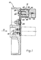
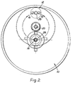
- Figures 1 and 2 show a rotary handwheel 10 for driving specimen clamping means (not shown) of a microtome in an oscillating linear movement relative to a cutting knife (not shown).
- the handwheel 10 has a crank handle 12 extending therefrom.
- a drive motor (not shown) is connectible to the handwheel 10 in order to provide a motor driven movement of the specimen clamping means.
- the crank handle 12 is arranged on positioning means in the form of a guide device 22 which is rotatable about an axis 20.
- the guide device 22 is shown as a disc, but it may have any suitable configuration.
- the axis 20 is spaced relative to the rotational axis 14 of the handwheel 10 and is substantially parallel thereto; this enables the crank handle 12 to be positioned in alignment with the rotational axis 14 of the handwheel 10 in one position of the guide device 22.
- the guide device 22 is provided with locking means in the form of a bearing sleeve 24 spaced radially relative to the axis 20 and axially parallel to the axis 20.
- the crank handle 12 is arranged on the bearing sleeve 24 and is slidable relative thereto; this enables the handle 12 to be selectively locked to, or unlocked from, the handwheel 10.
- the handwheel 10 is provided with a recess 26 which is disposed in alignment with the rotational axis 14 of the handwheel 10.
- the handwheel 10 is provided with a further recess 28 which is disposed diametrically opposite to the rotational axis 14 relative to the axis 20. If desired further recesses (not shown) can be provided in the handwheel 10.
- the crank handle 12 is provided with detent means in the form of a central pin 30 which is mounted axially slidably in the bearing sleeve 24.
- the central pin 30 is screwed to a screw-threaded lug 32 in the crank handle 12.
- the central pin 30 extends through an aperture provided in the guide device 22. When the crank handle is aligned with a selected one of the recesses 26 or 28, the central pin 30 can extend into the selected recesses 26 or 28 in the handwheel 10, thereby locking the crank handle 12 to the handwheel 10, and securing the crank handle 12 against torque.
- a spring element 36 is arranged between the central pin 30 and the bearing sleeve 24 to bias the crank handle 12 towards the handwheel 10 at all times; this biasses the central pin 30 towards the handwheel 10. This arrangement ensures that the central pin 30 extends into the selected recess 26 or 28 when the crank handle-12 is in alignment therewith.
- the spring element 36 comprises a helical compression spring which is arranged between a flange 38 on the central pin 30 and an abutment surface 39 at the end of a blind bore recess 40 in the bearing sleeve 24.
- the crank handle 12 When the crank handle 12 is locked in the position spaced from the rotational axis 14, then the handwheel 10 can be rotated by manual operation of the crank handle 12. This causes the specimen clamping means to move relative to the cutting knife at speed related to the speed at which the crank handle 12 is moved.
- the drive motor can be connected to the handwheel so that operation of the drive motor rotates the handwheel and the specimen clamping means.
- the crank handle 12 may be moved from the radially spaced position to the position aligned with the rotational axis 14. This is achieved by applying a force to the crank handle 12 in a direction away from the handwheel 10 to move the pin 30 out of the recess 28 spaced from the rotational axis 14. During the application of this force the flange 38 compresses the spring element 36.
- the handle 12 together with the guide device 22 may be rotated through 180° about the axis 20 until the crank handle 12 is aligned with the rotational axis 14.
- the spring element automatically biasses the pin 30 into the recess 26 on the rotational axis 14.
- crank handle 12 Once the crank handle 12 is disposed in alignment with the rotational axis 14, motor driven operation can safely begin. During the motor driven operation the crank handle rotates about the axis 14 but is not displaced relative thereto. When it is again desired to begin manual operation, the crank handle 12 is moved back to the position radially spaced from the rotational axis 14.
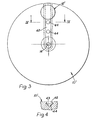
- Figure 3 shows another embodiment of a handwheel 10' for a microtome, having a crank handle 12' extending therefrom.
- the handwheel 10' can drive specimen clamping means (not shown) in an oscillating linear movement relative to a cutting knife (not shown).
- a drive motor (not shown) is connectible to the handwheel 10' in order to provide motor driven movement of the specimen clamping means.
- the crank handle 12' is adjustable between a position radially spaced from the rotational axis 14 of the handwheel 10' and a position aligned with the rotational axis 14. In Figure 3 the radially spaced position is indicated by solid lines and the aligned position by chain-dotted lines.
- the crank handle 12' is mounted slidably and lock- ably in positioning means in the form of a guideway 42 in the handwheel 10'.
- the guideway 42 extends radially from the centre of the handwheel 10' (i.e. from the rotational axis 14).
- the guideway 42 in the handwheel 10' is constructed as a groove of dovetail configuration.
- the crank handle 12' is provided with a sliding element 43 which is disposed in, and guided by, the groove 42.
- the sliding element may be provided with locking means in the form of a pin 30 as shown in Figure 1, for engagement with a selected one of the recesses 44 provided in the groove 42.
- One of the recesses 44 is disposed in the centre of the handwheel 10' aligned with the rotational axis 14.
- the locking means may comprise a ball spring (not shown) mounted in the sliding element, and the recesses 44 may be configured to match the shape of the ball spring.
- crank handle 12' is moved along a linear path instead of the circular path followed in the embodiment shown in Figures 1 and 2.
Landscapes
- Physics & Mathematics (AREA)
- General Physics & Mathematics (AREA)
- Engineering & Computer Science (AREA)
- Automation & Control Theory (AREA)
- Health & Medical Sciences (AREA)
- Life Sciences & Earth Sciences (AREA)
- Chemical & Material Sciences (AREA)
- Analytical Chemistry (AREA)
- Biochemistry (AREA)
- General Health & Medical Sciences (AREA)
- Immunology (AREA)
- Pathology (AREA)
- Sampling And Sample Adjustment (AREA)
- Mechanical Control Devices (AREA)
Applications Claiming Priority (2)
| Application Number | Priority Date | Filing Date | Title |
|---|---|---|---|
| DE19843435290 DE3435290C1 (de) | 1984-09-26 | 1984-09-26 | Mikrotom |
| DE3435290 | 1984-09-26 |
Publications (2)
| Publication Number | Publication Date |
|---|---|
| EP0176216A2 true EP0176216A2 (fr) | 1986-04-02 |
| EP0176216A3 EP0176216A3 (fr) | 1986-12-30 |
Family
ID=6246394
Family Applications (1)
| Application Number | Title | Priority Date | Filing Date |
|---|---|---|---|
| EP85305840A Withdrawn EP0176216A3 (fr) | 1984-09-26 | 1985-08-16 | Manivelle pour microtome entraíné par un moteur |
Country Status (3)
| Country | Link |
|---|---|
| EP (1) | EP0176216A3 (fr) |
| JP (1) | JPS6189537A (fr) |
| DE (1) | DE3435290C1 (fr) |
Family Cites Families (3)
| Publication number | Priority date | Publication date | Assignee | Title |
|---|---|---|---|---|
| GB848123A (en) * | 1957-12-02 | 1960-09-14 | Bruton Engineering Company Ltd | Improvements in or relating to handles for manually rotatable shafts, drums and the like |
| DE3032912A1 (de) * | 1980-09-02 | 1982-04-15 | Ernst Leitz Wetzlar Gmbh, 6330 Wetzlar | Mikrotomantrieb |
| IT1149640B (it) * | 1982-02-12 | 1986-12-03 | Elesa Spa | Maniglia ribaltabile di sicurezza a scatto automatico,particolarmente per volantini di manovra |
-
1984
- 1984-09-26 DE DE19843435290 patent/DE3435290C1/de not_active Expired
-
1985
- 1985-08-16 EP EP85305840A patent/EP0176216A3/fr not_active Withdrawn
- 1985-09-24 JP JP20904385A patent/JPS6189537A/ja active Granted
Also Published As
| Publication number | Publication date |
|---|---|
| JPH0533738B2 (fr) | 1993-05-20 |
| JPS6189537A (ja) | 1986-05-07 |
| DE3435290C1 (de) | 1985-06-27 |
| EP0176216A3 (fr) | 1986-12-30 |
Similar Documents
| Publication | Publication Date | Title |
|---|---|---|
| US5171111A (en) | Drilling tool | |
| US3542097A (en) | Chuck assembly for sabre saws | |
| US5832611A (en) | Variable angle reciprocating tool | |
| US4730952A (en) | Quick change mechanism for circular saw blades | |
| US5679066A (en) | Eccentric disk grinder with a grinding disk brake | |
| US5909986A (en) | Boring head with simultaneous clamping | |
| EP1644166B1 (fr) | Scie circulaire avec système d'indexation pour fixer la profondeur et l'angle de biseau de la coupe | |
| US3494390A (en) | Sabre saws with 360 degree swivel saw bar | |
| DE102010007714B3 (de) | Hand-Werkzeugmaschine mit einem Positionserfassungsmittel für ihre Werkzeugaufnahme | |
| DE10059712A1 (de) | Handwerkzeugmaschine | |
| US3207193A (en) | Rotary cutting tool | |
| EP1123171B1 (fr) | Outil a chanfreiner a arete unique portatif | |
| US4711055A (en) | Displaceable protective cover for handtools provided with rotatable disc-shaped tools | |
| US4594929A (en) | Microtome having specimen retraction means | |
| EP0471490A2 (fr) | Dispositif pour meuler des outils à fonction multiple | |
| WO1994021410A1 (fr) | Machine a fabriquer des cles | |
| DE69405935T2 (de) | Vorrichtung zum manuellen Anbringen und Abmontieren von Bearbeitungsscheiben auf Handwerkzeugmaschinen für Oberflächenbearbeitung | |
| JP2002046017A (ja) | 工作機械 | |
| EP0176216A2 (fr) | Manivelle pour microtome entraîné par un moteur | |
| JPH0160362B2 (fr) | ||
| GB2182786A (en) | Microtome having specimen holder movable in two directions | |
| EP0045433B1 (fr) | Machine à meuler ou à polir comprenant une broche porte-outil entraînée d'un mouvement axial oscillant et d'un mouvement rotatif | |
| US4080698A (en) | Accessory for a hand drill | |
| US4890419A (en) | Device for grinding cutting tools having straight and spiral grooves | |
| JPH0248369B2 (ja) | Senkosochi |
Legal Events
| Date | Code | Title | Description |
|---|---|---|---|
| PUAI | Public reference made under article 153(3) epc to a published international application that has entered the european phase |
Free format text: ORIGINAL CODE: 0009012 |
|
| AK | Designated contracting states |
Kind code of ref document: A2 Designated state(s): FR GB SE |
|
| PUAL | Search report despatched |
Free format text: ORIGINAL CODE: 0009013 |
|
| AK | Designated contracting states |
Kind code of ref document: A3 Designated state(s): FR GB SE |
|
| STAA | Information on the status of an ep patent application or granted ep patent |
Free format text: STATUS: THE APPLICATION IS DEEMED TO BE WITHDRAWN |
|
| 18D | Application deemed to be withdrawn |
Effective date: 19870701 |
|
| GBT | Gb: translation of ep patent filed (gb section 77(6)(a)/1977) | ||
| RIN1 | Information on inventor provided before grant (corrected) |
Inventor name: KEMPE, MANFRED |