EP0175673B1 - Exchanging device for the work piece clamp of a gripping head - Google Patents
Exchanging device for the work piece clamp of a gripping head Download PDFInfo
- Publication number
- EP0175673B1 EP0175673B1 EP85890159A EP85890159A EP0175673B1 EP 0175673 B1 EP0175673 B1 EP 0175673B1 EP 85890159 A EP85890159 A EP 85890159A EP 85890159 A EP85890159 A EP 85890159A EP 0175673 B1 EP0175673 B1 EP 0175673B1
- Authority
- EP
- European Patent Office
- Prior art keywords
- devices
- housing
- locking
- chucking
- coupling
- Prior art date
- Legal status (The legal status is an assumption and is not a legal conclusion. Google has not performed a legal analysis and makes no representation as to the accuracy of the status listed.)
- Expired
Links
- 238000010168 coupling process Methods 0.000 claims description 49
- 230000008878 coupling Effects 0.000 claims description 46
- 238000005859 coupling reaction Methods 0.000 claims description 46
- 238000006073 displacement reaction Methods 0.000 claims 1
- 238000003780 insertion Methods 0.000 description 9
- 230000037431 insertion Effects 0.000 description 9
- 238000006243 chemical reaction Methods 0.000 description 1
- 230000007812 deficiency Effects 0.000 description 1
- 238000000034 method Methods 0.000 description 1
Images


Classifications
-
- B—PERFORMING OPERATIONS; TRANSPORTING
- B25—HAND TOOLS; PORTABLE POWER-DRIVEN TOOLS; MANIPULATORS
- B25J—MANIPULATORS; CHAMBERS PROVIDED WITH MANIPULATION DEVICES
- B25J15/00—Gripping heads and other end effectors
- B25J15/04—Gripping heads and other end effectors with provision for the remote detachment or exchange of the head or parts thereof
- B25J15/0491—Gripping heads and other end effectors with provision for the remote detachment or exchange of the head or parts thereof comprising end-effector racks
-
- B—PERFORMING OPERATIONS; TRANSPORTING
- B23—MACHINE TOOLS; METAL-WORKING NOT OTHERWISE PROVIDED FOR
- B23Q—DETAILS, COMPONENTS, OR ACCESSORIES FOR MACHINE TOOLS, e.g. ARRANGEMENTS FOR COPYING OR CONTROLLING; MACHINE TOOLS IN GENERAL CHARACTERISED BY THE CONSTRUCTION OF PARTICULAR DETAILS OR COMPONENTS; COMBINATIONS OR ASSOCIATIONS OF METAL-WORKING MACHINES, NOT DIRECTED TO A PARTICULAR RESULT
- B23Q7/00—Arrangements for handling work specially combined with or arranged in, or specially adapted for use in connection with, machine tools, e.g. for conveying, loading, positioning, discharging, sorting
- B23Q7/04—Arrangements for handling work specially combined with or arranged in, or specially adapted for use in connection with, machine tools, e.g. for conveying, loading, positioning, discharging, sorting by means of grippers
- B23Q7/043—Construction of the grippers
Definitions
- the invention relates to a device for changing a workpiece clamping device which can be rigidly connected to a gripper head, comprising a gripper head attached to an adjustable support arm, which has at least one connecting flange for at least one clamping device, and a clamping device which can be connected to this connecting flange and is provided with a separate Housing that houses a rigid drive that can be coupled to a drive in the gripper head for the gripper tools, and a magazine with holders for various clamping devices.
- Gripper heads for loading and unloading machine tools have at least one clamping device with gripping tools for the workpieces, which can be conveyed back and forth between at least one workpiece storage device and the machine tool by means of the gripper head which can be adjusted by means of a support arm. Since, on the one hand, the adjustment path of the gripping tools of the clamping devices is limited and, on the other hand, different gripping tools are required, for example for clamping shafts or chuck parts, it is necessary to convert the gripper heads accordingly. It is to keep the machine tool downtime necessary for the changeover as short as possible.
- the two clamping devices with the common housing to be replaced by correspondingly converted clamping devices.
- the housing with the two clamping devices is exchangeably fastened to a connecting flange of the gripper head, with the fastening of the housing of the clamping devices to the connecting flange of the actuating drive accommodated in this housing for the gripping tools being independently coupled with a drive in the gripper head.
- the invention is therefore based on the object of avoiding these deficiencies and of creating a device for mechanically changing the workpiece clamping device of a gripper head.
- This device should be comparatively simple and not require any additional drives.
- the invention achieves the stated object in that the connecting flange carries coupling bolts projecting vertically from its connecting surface, for which corresponding receiving openings are provided in the housing of the clamping device, that the housing of the clamping device has a locking device with a for each coupling pin against the force of a closing spring from the outside adjustable closure piece and that the magazine forms in the area of the brackets for the tensioning devices positioning and holding stops for the locking pieces of the locking devices.
- the locking device holds the coupling bolts inserted into the receiving openings, so that only the drive already provided for the movement of the support arm is required for the coupling process.
- the locking itself is carried out via the closing spring, which presses the adjustable closure piece of the locking device into the closed position.
- a prerequisite for this simple coupling process, however, is that when a clamping device is coupled to the gripper head, the locking device is in an unlocked position.
- the magazine is provided with positioning and holding stops for the locking pieces of the locking devices. If a tensioning device is inserted into the holder of the magazine, the actuating and holding stops press on the locking pieces of the locking device which, due to the relative movement between the tensioning device and the actuating and holding stops, are pressed against the force of the closing spring into the unlocking position and held in this unlocking position will.
- the locking devices are thus automatically unlocked when the tensioning devices are inserted into the holders of the magazine via the positioning and holding stops provided for them, so that when the tensioning devices are coupled to the connecting flange, the coupling bolts can freely engage in the receiving openings.
- the holding devices of the magazine form guides for the clamping devices running transversely to the direction of adjustment of the locking pieces of the taken-up clamping devices.
- the tensioning devices are in this guide stanchions relentlessly supported, so that the closure pieces are inevitably held in the unlocked position by the actuating and holding stops, because the direction of adjustment of the closure pieces extends transversely to the support of the tensioning devices.
- the guides for the tensioning devices consist of guide slots for guide pins provided on opposite side walls of the housing of the tensioning devices.
- these guide pins engage in the guide slots provided, which represent a positive guide for the housing of the clamping devices. This also ensures the relative movement between the actuating and holding stops and the housing of the tensioning devices required for unlocking the locking pieces by simple means.
- the locking pieces of the locking devices can be adjustable via driver pins which run parallel to the guide pins of the housing of the tensioning device. These driver pins are forced into the slots forming the actuating and holding stops, the actuating movement of the locking pieces depending on the change in distance measured in the direction of the adjusting movement of the locking pieces between the guide surfaces of the guide slots for the guide pins and the guide surfaces of the slots for the driver pins.
- the movement of the closure pieces can be made largely independent of the insertion movement of the clamping devices into the holders of the magazine if the positioning and holding stops for the closure pieces of the locking device have a run-on slope which determines the adjustment movement of the closure pieces.
- the adjustment direction of the closure pieces depends only on the possible directions of movement of the gripper head, because the movement of the gripper head relative to the magazine causes the adjustment of the closure pieces, it is particularly advantageous to slide the closure pieces of the locking devices parallel to the axis of the receiving openings for the coupling pins. In this case, the clamping devices can be inserted into the holders of the magazine in the coupling direction.
- the receiving openings for the coupling bolts can be formed by a housing-fixed sleeve which has openings for balls which engage in an annular groove of the coupling bolt and form locking bodies
- the closure piece having a bush which is axially displaceably mounted on the sleeve comprises, which is held by the closing spring in a closed position covering the openings for the balls and can be pushed away from the openings against the force of the closing spring.
- the bushing which results in the closure piece covers the openings in the housing-fixed sleeve, so that the balls provided in the openings cannot emerge from the annular groove of the coupling bolt and hold the coupling bolt in the axial direction.
- the balls can move radially outward through the openings in the event of an axial bolt movement.
- the coupling pin is therefore released.
- the balls are again pressed through the openings against the annular groove of the bolt and held in the engaged position.
- a stamp can be slidably mounted in the housing-fixed sleeve, which can be inserted into the receiving opening against the force of a spring from a stop position covering the openings for the balls through the coupling bolt. In its stop position, the stamp covers the openings in the housing-fixed sleeve from the inside, so that the balls cannot fall into the sleeve.
- the plunger Due to the coupling pin engaging in the receiving opening, the plunger is pressed against the spring force into the receiving opening, the openings in the sleeve initially being covered by the coupling pin until the coupling pin is fully inserted into the receiving opening and the openings are in the area of the annular groove.
- the plunger is pressed onto the coupling bolt until the stop position is reached, in which the openings are covered again.
- a lathe 1 is to be loaded and unloaded, the chuck of which is designated by 2.
- a gripper head 3 with two workpiece clamping devices 4 is provided, which is arranged on a support arm 5.
- This support arm 5 is guided vertically displaceably in a cross slide 6 and can be raised and lowered by means of a cylinder 7.
- the cross slide 6 is supported on a longitudinal slide 8 which can be moved on guide tracks 9 in the direction of the main axis of the lathe 1.
- the gripper head 3 can thus be moved in three mutually perpendicular axes.
- clamping devices 4 can be pivoted through 180 ° about a common axis of rotation running parallel to the adjustment direction of the cross slide 6, in order to remove the finished workpiece from the chuck 2 of the lathe 1 with one of the two clamping devices 4 and then one with the help of the other clamping device to be able to insert the workpiece to be machined into the chuck 2 without having to adjust the gripper head 3 vertically via the support arm 5.
- the clamping devices must be adapted to the workpiece geometry.
- the gripper head 3 must therefore be converted for processing such different workpieces by replacing the clamping devices 4.
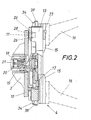
- the gripper head 3 according to FIG. 2 has a connecting flange 10 which bears vertically projecting coupling bolts 11. These coupling bolts 11 engage in receiving openings 12 'of the housing 13 of the tensioning device 4 and are held in the receiving openings 12 by a releasable locking device 14 (FIG. 4).
- the actuator of the clamping devices 4 When connecting the clamping devices 4 to the gripper head 3, the actuator of the clamping devices 4 must of course also be coupled to the drive of the gripper head 3.
- the actuator for the radially displaceably mounted clamping jaws 15, which carry the gripper tools 16 interchangeably, according to the exemplary embodiment consists of a flat spiral disk 17 rotatably mounted in the housing 13, which engages in a corresponding flat spiral section of the clamping jaws 15 and via a connecting shaft 18 can be driven.
- This connecting shaft 18 is designed as a polygonal shaft and forms a plug-in coupling with a plug sleeve 19 of opposite shape.
- the receptacle 19 is non-rotatably but axially displaceably inserted in a hollow output shaft 20 of the gripper head 3 and acted upon by a spring 21. If the rotational position of the connecting shaft 18 does not coincide with the rotational position of the plug-in sleeve 19 when the clamping device 4 is coupled to the connecting flange 10, then the plug-in sleeve 19 is inserted into the output shaft 20 of the gripper head 3 against the force of the spring 21 without inserting the coupling bolts 11 in the receiving openings 12 and thus to hinder the connection process.
- the plug-in sleeve 19 is pushed onto the connecting shaft 18 by the spring 21 and a positive drive connection is established as soon as mutually overlapping rotational positions are reached.
- the tensioning device 4 can then be adjusted in both directions via the output shaft 20.
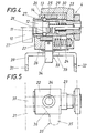
- the locking device 14 for the coupling bolts 11 engaging in the receiving openings 12 consists of a locking piece 22 which is mounted axially displaceably on a sleeve 23 fixed to the housing and which is acted upon by a locking spring 24 in the closing direction of the locking device.
- the locking device 14 comprises a bushing 25 which interacts with balls 26 forming locking bodies. These balls 26 are inserted into openings 27 of the sleeve 23 resulting in the receiving openings 12 and engage in the locking position in an annular groove 28 of the coupling bolts 11. In this locking position, the bushing 25 covers the openings 27 in the sleeve 23, as is shown in the lower part of FIG. 4.
- the locking piece 22 To unlock, the locking piece 22 must be moved against the force of the closing spring 24 on the sleeve 23 in order to release the balls 26 as shown in the upper part of FIG. 4, which accordingly deflect radially outwards when the coupling bolt 11 is pulled out of the receiving opening 12 can. So that the balls 26 cannot get out of the openings 27 into the interior of the sleeve 23, a plunger 29 is slidably guided within the sleeve 23 and is held in a stop position by a spring 30 in which it covers the openings 27. This plunger 29 is pushed back against the force of the spring 30 when the coupling bolt 11 is inserted into the receiving opening 12, the balls 26 reaching the area of the annular groove 28, as can be seen in the lower part of FIG. 4. If the closure piece 22 is released in this coupling position, the closing spring 24 presses the bushing 25 into the closed position covering the openings 27, in which the coupling bolt 11 is locked in the receiving opening 12.
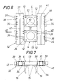
- the clamping devices 4 provided for the exchange are accommodated in corresponding holders 31 of a magazine 32.
- This magazine 32 forms in the area of the brackets 31 positioning and holding stops 33 for the closure pieces 22 which, when the respective clamping device 4 is inserted into the Brackets are adjusted by the actuating and holding stops 33, specifically via driver pins 34 inserted into the locking pieces 22.
- the arrangement is such that the actuating and holding stops are formed by guide slots 35 which have a run-on slope 36 for the driver pins 34 .
- the brackets themselves are provided with guide slots 37 for guide pins 38, which run parallel to the driver pins 34 and are arranged laterally on the housing 13 of the clamping devices 4.
- the guide slots 37 form a guide extending transversely to the direction of adjustment of the locking pieces 22 of the tensioning devices received, so that when the tensioning devices 4 are inserted into these guide slots 37, the driver pins 34 of the locking pieces 22 are not only adjusted along the run-up bevel 36 against the force of the closing spring 24 in the unlocking direction, but also be held in the unlocked position.
- the run-up slope 36 thus forms the actuating part and the adjoining parallel section of the guide slot 35 the holding part of the actuating and holding stops 33. Since the actuating movement of the locking pieces 22 runs in the coupling direction, the tensioning device with the aid of the gripper head 3 must be inserted into the guide slots 36 transversely to the coupling direction , 37 are introduced.
- the guide slots 36, 37 are therefore accessible via insertion slots 39 in the brackets 31. These insertion slots are open on both sides, so that the clamping devices can also be removed and inserted from the side facing away from the gripper head.
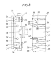
- the clamping devices 4 are held in the guide slots 37 extending transversely to the coupling direction in the magazine 32, which requires the clamping devices to be introduced into the brackets 31 in two mutually perpendicular directions, as indicated by the arrows 40, the coupling bolts can be pulled out of the Receiving openings or the insertion of the coupling bolts into the receiving openings of the tensioning devices are not difficult, because the tensioning devices are supported accordingly in this direction.
- the movement of the gripper head 3 in two mutually perpendicular directions in accordance with the course of the insertion slots 39 and the guide slots 37 extending therefrom can be carried out without problems in the case of the gripper bearing, which is adjustable in three axes.
- brackets 31 consist of cross-sectionally U-shaped profiles which are fastened on opposite sides by uprights 41 and form the guide slots for the clamping devices, as can be seen in FIGS. 6 and 7 can.
- the guide pins 38 can have a different diameter than the driver pins 34, the insertion slots 39 having opening widths corresponding to these diameters.
- the gripper head is provided with a connecting plate 10 and coupling bolts 11, not only clamping devices 4, but also other tools or tool parts can be connected to the gripper head, which are required, for example, to convert the lathe. For this purpose, these conversion parts only need to be provided with corresponding locking devices 14. With the help of such a gripper head, z. B. a chuck change can be carried out mechanically. If the two clamping devices 4 form a structural unit, this structural unit can also be replaced instead of the two clamping devices.
Landscapes
- Engineering & Computer Science (AREA)
- Mechanical Engineering (AREA)
- Robotics (AREA)
- Mounting, Exchange, And Manufacturing Of Dies (AREA)
- Jigs For Machine Tools (AREA)
Description
Die Erfindung bezieht sich auf eine Vorrichtung zum Wechseln einer mit einem Greiferkopf starr verbindbaren Werkstück-Spanneinrichtung, bestehend aus einem an einem verstellbaren Tragarm angebrachten Greiferkopf, der wenigstens einen Anschlußflansch für mindestens eine Spanneinrichtung aufweist, aus einer an diesem Anschlußflansch anschließbaren Spanneinrichtung versehen mit einem gesonderten Gehäuse, das einen mit einem Antrieb im Greiferkopf kuppelbaren Steiftrieb für die Greiferwerkzeuge aufnimmt, und aus einem Magazin mit Halterungen für verschiedene Spanneinrichtungen.The invention relates to a device for changing a workpiece clamping device which can be rigidly connected to a gripper head, comprising a gripper head attached to an adjustable support arm, which has at least one connecting flange for at least one clamping device, and a clamping device which can be connected to this connecting flange and is provided with a separate Housing that houses a rigid drive that can be coupled to a drive in the gripper head for the gripper tools, and a magazine with holders for various clamping devices.
Greiferköpfe zum Be- und Entladen von Werkzeugmaschinen, insbesondere Drehmaschinen, weisen wenigstens eine Spanneinrichtung mit Greifwerkzeugen für die Werkstücke auf, die mittels des durch einen Tragarm verstellbaren Greiferkopfes zwischen wenigstens einem Werkstückspeicher und der Werkzeugmaschine hin- und hergefördert werden können. Da einerseits der Stellweg der Greifwerkzeuge der Spanneinrichtungen begrenzt ist und anderseits unterschiedliche Greifwerkzeuge beispielsweise zum Spannen von Wellen oder Futterteilen benötigt werden, ist es erforderlich, die Greiferköpfe entsprechend umzurüsten. Um die für das Umrüsten notwendige Stillstandszeit der Werkzeugmaschine möglichst klein zu halten, ist es. bei Greiferköpfen mit zwei einander diametral gegenüberliegenden Spanneinrichtungen bekannt (DE-A-3 043 687), die beiden Spanneinrichtungen mit dem gemeinsamen Gehäuse gegen entsprechend umgerüstete Spanneinrichtungen auszuwechseln. Zu diesem Zweck ist das Gehäuse mit den beiden Spanneinrichtungen an einem Anschlußflansch des Greiferkopfes austauschbar befestigt, wobei mit der Befestigung des Gehäuses der Spanneinrichtungen am Anschlußflansch der in diesem Gehäuse untergebrachte Stelltrieb für die Greifwerkzeuge mit einem Antrieb im Greiferkopf selbständig gekuppelt wird. Damit wird zwar der Austausch der Spanneinrichtungen erleichtert, doch bleibt die Notwendigkeit bestehen, die auszutauschenden Spanneinrichtungen von Hand aus vom Greiferkopf zu lösen und die neuen Spanneinrichtungen wiederum von Hand aus am Greiferkopf zu befestigen.Gripper heads for loading and unloading machine tools, in particular lathes, have at least one clamping device with gripping tools for the workpieces, which can be conveyed back and forth between at least one workpiece storage device and the machine tool by means of the gripper head which can be adjusted by means of a support arm. Since, on the one hand, the adjustment path of the gripping tools of the clamping devices is limited and, on the other hand, different gripping tools are required, for example for clamping shafts or chuck parts, it is necessary to convert the gripper heads accordingly. It is to keep the machine tool downtime necessary for the changeover as short as possible. in gripper heads with two diametrically opposite clamping devices known (DE-A-3 043 687), the two clamping devices with the common housing to be replaced by correspondingly converted clamping devices. For this purpose, the housing with the two clamping devices is exchangeably fastened to a connecting flange of the gripper head, with the fastening of the housing of the clamping devices to the connecting flange of the actuating drive accommodated in this housing for the gripping tools being independently coupled with a drive in the gripper head. Although this simplifies the exchange of the clamping devices, there remains the need to manually remove the clamping devices to be replaced from the gripper head and to fix the new clamping devices manually to the gripper head.
Der Erfindung liegt somit die Aufgabe zugrunde, diese Mängel zu vermeiden und eine Vorrichtung zum maschinellen Wechseln der Werkstück-spanneinrichtung eines Greiferkopfes zu schaffen. Diese Vorrichtung soll vergleichsweise einfach aufgebaut sein und keine zusätzlichen Antriebe benötigen.The invention is therefore based on the object of avoiding these deficiencies and of creating a device for mechanically changing the workpiece clamping device of a gripper head. This device should be comparatively simple and not require any additional drives.
Ausgehend von einer Vorrichtung der eingangs geschilderten Art löst die Erfindung die gestellte Aufgabe dadurch, daß der Anschlußflansch von seiner Anschlußfläche senkrecht abstehende Kupplungsbolzen trägt, für die entsprechende Aufnahmeöffnungen im Gehäuses der Spanneinrichtung vorgesehen sind, daß das Gehäuse der Spanneinrichtung für jeden Kupplungsbolzen eine Verriegelungseinrichtung mit einem gegen die Kraft einer Schließfeder von außen verstellbaren Verschlußstück aufweist und daß das Magazin im Bereich der Halterungen für die Spanneinrichtungen Stell- und Halteanschläge für die Verschlußstücke der Verriegelungseinrichtungen bildet.Starting from a device of the type described in the introduction, the invention achieves the stated object in that the connecting flange carries coupling bolts projecting vertically from its connecting surface, for which corresponding receiving openings are provided in the housing of the clamping device, that the housing of the clamping device has a locking device with a for each coupling pin against the force of a closing spring from the outside adjustable closure piece and that the magazine forms in the area of the brackets for the tensioning devices positioning and holding stops for the locking pieces of the locking devices.
Die zum Anschlußflansch senkrechten Kupp-. lungsbolzen, die in entsprechende Aufnahmeöffnungen des Gehäuses der Spanneinrichtung eingreifen, erlauben ein einfaches Aufschieben der jeweiligen Spanneinrichtung auf die Kupplungsbolzen, weil der Tragarm für den Greiferkopf lediglich in Richtung dieser Kupplungsbolzen verstellt werden muß. Die Verriegelungseinrichtung hält dabei die in die Aufnahmeöffnungen eingeführten Kupplungsbolzen fest, so daß für den Kupplungsvorgang lediglich der bereits für die Bewegung des Tragarmes vorgesehene Antrieb benötigt wird. Die Verriegelung selbst wird über die Schließfeder durchgeführt, die das verstellbare Verschlußstück der Verriegelungseinrichtung in die Schließstellung drückt. Voraussetzung für diesen einfachen Kupplungsvorgang ist allerdings, daß beim Ankuppeln einer Spanneinrichtung an den Greiferkopf die Verriegelungseinrichtung sich in einer Entriegelungsstellung befindet. Zu diesem Zweck ist das Magazin mit Stell-und Halteanschlägen für die Verschlußstücke der Verriegelungseinrichtungen versehen. Wird eine Spanneinrichtung in die Halterung des Magazins eingeführt, so drücken die Stell- und Halteanschläge auf die Verschlußstücke der Verriegelungseinrichtung, die zufolge der Relativbewegung zwischen der Spanneinrichtung und den Stell- und Halteanschlägen gegen die Kraft der Schließfeder in die Entriegelungsstellung gedrückt und in dieser Entriegelungsstellung gehalten werden. Die Verriegelungseinrichtungen werden somit beim Einführen der Spanneinrichtungen in die Halterungen des Magazins über die hiefür vorgesehenen Stell- und Halteanschläge automatisch entriegelt, so daß beim Ankuppeln der Spanneinrichtungen an dem Anschlußflansch die Kupplungsbolzen unbehindert in die Aufnahmeöffnungen eingreifen können. Wird die Spanneinrichtung über die Kupplungsbolzen des Anschlußflansches aus der Halterung entnommen; was zumindest eine Teilbewegung des Greiferkopfes quer zu den Kupplungsbolzen erfordert, so werden die Verschlußstücke von den Stell- und Halteanschlägen freigegeben und die Verriegelungseinrichtungen geschlossen, womit der Ankupplungsvorgang beendet ist.The vertical coupling to the connecting flange. lungsbolzen, which engage in corresponding receiving openings of the housing of the clamping device, allow a simple pushing the respective clamping device onto the coupling bolt, because the support arm for the gripper head only has to be adjusted in the direction of this coupling bolt. The locking device holds the coupling bolts inserted into the receiving openings, so that only the drive already provided for the movement of the support arm is required for the coupling process. The locking itself is carried out via the closing spring, which presses the adjustable closure piece of the locking device into the closed position. A prerequisite for this simple coupling process, however, is that when a clamping device is coupled to the gripper head, the locking device is in an unlocked position. For this purpose, the magazine is provided with positioning and holding stops for the locking pieces of the locking devices. If a tensioning device is inserted into the holder of the magazine, the actuating and holding stops press on the locking pieces of the locking device which, due to the relative movement between the tensioning device and the actuating and holding stops, are pressed against the force of the closing spring into the unlocking position and held in this unlocking position will. The locking devices are thus automatically unlocked when the tensioning devices are inserted into the holders of the magazine via the positioning and holding stops provided for them, so that when the tensioning devices are coupled to the connecting flange, the coupling bolts can freely engage in the receiving openings. If the clamping device is removed from the bracket via the coupling bolts of the connecting flange; which requires at least a partial movement of the gripper head transversely to the coupling bolts, the locking pieces are released from the actuating and holding stops and the locking devices are closed, thus completing the coupling process.
Um die Verschlußstücke der in die Halterungen des Magazins eingesetzten Spanneinrichtungen sicher in der Entriegelungsstellung zu halten, ist es vorteilhaft, wenn die Halterungen des Magazins quer zur Verstellrichtung der Verschlußstücke der aufgenommenen Spanneinrichtungen verlaufende Führungen für die Spanneinrichtungen bilden. Die Spanneinrichtungen sind in diesen Führungen unnachgiebig abgestützt, so daß die Verschlußstücke durch die Stell- und Halteanschläge zwangsläufig in der Entriegelungsstellung gehalten werden, weil ja die Verstellrichtung der Verschlußstücke quer zur Abstützung der Spanneinrichtungen verläuft.In order to hold the locking pieces of the clamping devices inserted into the holders of the magazine securely in the unlocked position, it is advantageous if the holding devices of the magazine form guides for the clamping devices running transversely to the direction of adjustment of the locking pieces of the taken-up clamping devices. The tensioning devices are in this guide stanchions relentlessly supported, so that the closure pieces are inevitably held in the unlocked position by the actuating and holding stops, because the direction of adjustment of the closure pieces extends transversely to the support of the tensioning devices.
Besonders einfache Konstruktionsverhältnisse werden dabei sichergestellt, wenn die Führungen für die Spanneinrichtungen aus Führungsschlitzen für auf gegenüberliegenden Seitenwänden des Gehäuses der Spanneinrichtungen vorgesehene Führungsstifte bestehen. Diese Führungsstifte greifen beim Einführen der Spanneinrichtungen in die Halterungen des Magazins in die vorgesehenen Führungsschlitze ein, die für das Gehäuse der Spanneinrichtungen eine Zwangsführung darstellen. Damit ist auch die für die Entriegelung der Verschlußstücke erforderliche Relativbewegung zwischen den Stell- und Halteanschlägen und dem Gehäuse der Spanneinrichtungen mit einfachen Mitteln gewährleistet.Particularly simple constructional relationships are ensured if the guides for the tensioning devices consist of guide slots for guide pins provided on opposite side walls of the housing of the tensioning devices. When the clamping devices are inserted into the holders of the magazine, these guide pins engage in the guide slots provided, which represent a positive guide for the housing of the clamping devices. This also ensures the relative movement between the actuating and holding stops and the housing of the tensioning devices required for unlocking the locking pieces by simple means.
Um auch die Stell- und Halteanschläge in Form von Führungsschlitzen ausbilden zu können, können die Verschlußstücke der Verriegelungseinrichtungen über Mitnehmerstifte verstellbar sein, die parallel zu den Führungsstiften des Gehäuses der Spanneinrichtung verlaufen. Diese Mitnehmerstifte erfahren in den die Stell- und Halteanschläge bildenden Schlitzen eine Zwangsführung, wobei die Stellbewegung der Verschlußstücke von der in Richtung der Verstellbewegung der Verschlußstücke gemessenen Abstandsänderung zwischen den Führungsflächen der Führungsschlitze für die Führungsstifte und den Führungsflächen der Schlitze für die Mitnehmerstifte abhängt.In order to also be able to form the positioning and holding stops in the form of guide slots, the locking pieces of the locking devices can be adjustable via driver pins which run parallel to the guide pins of the housing of the tensioning device. These driver pins are forced into the slots forming the actuating and holding stops, the actuating movement of the locking pieces depending on the change in distance measured in the direction of the adjusting movement of the locking pieces between the guide surfaces of the guide slots for the guide pins and the guide surfaces of the slots for the driver pins.
Die Bewegung der Verschlußstücke kann dabei von der Einführbewegung der Spanneinrichtungen in die Halterungen des Magazins weitgehend unabhängig gestaltet werden, wenn die Stell- und Halteanschläge für die Verschlußstücke der Verriegelungseinrichtung eine Anlaufschräge aufweisen, die die Stellbewegung der Verschlußstücke bestimmt.The movement of the closure pieces can be made largely independent of the insertion movement of the clamping devices into the holders of the magazine if the positioning and holding stops for the closure pieces of the locking device have a run-on slope which determines the adjustment movement of the closure pieces.
Obwohl die Verstellrichtung der Verschlußstücke lediglich von den möglichen Bewegungsrichtungen des Greiferkopfes abhängt, weil durch die Bewegung des Greiferkopfes gegenüber dem Magazin die Verstellung der Verschlußstücke erfolgt, ist es besonders vorteilhaft, die Verschlußstücke der Verriegelungseinrichtungen parallel zur Achse der Aufnahmeöffnungen für die Kupplungszapfen verschiebbar zu führen. Die Spanneinrichtungen können nämlich in diesem Fall in der Kupplungsrichtung in die Halterungen des Magazins eingeführt werden.Although the adjustment direction of the closure pieces depends only on the possible directions of movement of the gripper head, because the movement of the gripper head relative to the magazine causes the adjustment of the closure pieces, it is particularly advantageous to slide the closure pieces of the locking devices parallel to the axis of the receiving openings for the coupling pins. In this case, the clamping devices can be inserted into the holders of the magazine in the coupling direction.
Um konstruktiv einfache Verriegelungseinrichtungen vorzusehen, die wenig Platz beanspruchen, können die Aufnahmeöffnungen für die Kupplungsbolzen durch eine gehäusefeste Hülse gebildet werden, die Durchbrüche für in eine Ringnut des Kupplungsbolzens eingreifende, Riegelkörper bildende Kugeln aufweist, wobei das Verschlußstück eine auf der Hülse axial verschiebbar gelagerte Buchse umfaßt, die durch die Schließfeder in einer die Durchbrüche für die Kugeln abdeckenden Schließstellung gehalten und gegen die Kraft der Schließfeder von den Durchbrüchen wegschiebbar ist. In der Schließstellung deckt die das Verschlußstück ergebende Buchse die Durchbrüche in der gehäusefesten Hülse ab, so daß die in den Durchbrüchen vorgesehenen Kugeln nicht aus der Ringnut des Kupplungsbolzens austreten können und den Kupplungsbolzen in axialer Richtung festhalten. Wird die Buchse gegen die Kraft der Schließfeder beim Einführen der Spanneinrichtung in die Halterung des Magazins über einen Stell- und Halteanschlag von den Durchbrüchen weggeschoben, so können die Kugeln bei einer axialen Bolzenbewegung radial nach außen durch die Durchbrüche ausweichen. Der Kupplungsbolzen wird daher freigegeben. Bei der gegensinnigen Bewegung der das Verschlußstück bildenden Buchse werden die Kugeln wieder durch die Durchbrüche gegen die Ringnut des Bolzens gedrückt und in der Eingriffsstellung festgehalten.In order to provide structurally simple locking devices which take up little space, the receiving openings for the coupling bolts can be formed by a housing-fixed sleeve which has openings for balls which engage in an annular groove of the coupling bolt and form locking bodies, the closure piece having a bush which is axially displaceably mounted on the sleeve comprises, which is held by the closing spring in a closed position covering the openings for the balls and can be pushed away from the openings against the force of the closing spring. In the closed position, the bushing which results in the closure piece covers the openings in the housing-fixed sleeve, so that the balls provided in the openings cannot emerge from the annular groove of the coupling bolt and hold the coupling bolt in the axial direction. If the bushing is pushed away from the openings against the force of the closing spring when the tensioning device is inserted into the holder of the magazine via an actuating and holding stop, the balls can move radially outward through the openings in the event of an axial bolt movement. The coupling pin is therefore released. During the opposite movement of the bushing forming the closure piece, the balls are again pressed through the openings against the annular groove of the bolt and held in the engaged position.
Wenn die die Riegelkörper bildenden Kugeln nicht in einem Käfig od. dgl. gefangen sind, besteht die Gefahr, daß beim Lösen des Kupplungsbolzens die Kugeln aus den Durchbrüchen in die gehäusefeste Hülse fallen. Dies muß verhindert werden. Zu diesem Zweck kann in der gehäusefesten Hülse ein Stempel verschiebbar gelagert sein, der gegen die Kraft einer Feder aus einer die Durchbrüche für die Kugeln abdeckenden Anschlagstellung durch den Kupplungsbolzen in die Aufnahmeöffnung einschiebbar ist. In seiner Anschlagstellung deckt der Stempel die Durchbrüche in der gehäusefesten Hülse von innen her ab, so daß die Kugeln nicht in die Hülse fallen können. Durch den in die Aufnahmeöffnung eingreifenden Kupplungsbolzen wird der Stempel gegen die Federkraft in die Aufnahmeöffnung hineingedrück, wobei die Durchbrüche in der Hülse zunächst durch den Kupplungsbolzen abgedeckt bleiben, bis der Kupplungsbolzen zur Gänze in die Aufnahmeöffnung eingeführt ist und die Durchbrüche im Bereich der Ringnut liegen. Beim Entkuppeln wird der Stempel an den Kupplungsbolzen angedrückt bis die Anschlagstellung erreicht ist, in der die Durchbrüche wiederum abgedeckt sind.If the balls forming the locking body are not caught in a cage or the like, there is a risk that when the coupling bolt is loosened, the balls will fall out of the openings into the sleeve fixed to the housing. This must be prevented. For this purpose, a stamp can be slidably mounted in the housing-fixed sleeve, which can be inserted into the receiving opening against the force of a spring from a stop position covering the openings for the balls through the coupling bolt. In its stop position, the stamp covers the openings in the housing-fixed sleeve from the inside, so that the balls cannot fall into the sleeve. Due to the coupling pin engaging in the receiving opening, the plunger is pressed against the spring force into the receiving opening, the openings in the sleeve initially being covered by the coupling pin until the coupling pin is fully inserted into the receiving opening and the openings are in the area of the annular groove. When uncoupling, the plunger is pressed onto the coupling bolt until the stop position is reached, in which the openings are covered again.
In der Zeichnung ist der Erfindungsgegenstand beispielsweise dargestellt. Es zeigen
- Fig. 1 eine erfindungsgemäße Wechselvorrichtung für eine Drehmaschine in einer vereinfachten Stirnansicht.
- Fig. 2 eine an den Anschlußflansch eines Greiferkopfes angekuppelte Spanneinrichtung in einer teilweise aufgerissenen Seitenansicht in einem größeren Maßstab,
- Fig. 3 diese Spanneinrichtung in einer Draufsicht auf die Kuppelseite,
- Fig. 4 eine Verriegelungseinrichtung für den Kupplungsbolzen des Anschlußflansches im Schnitt in einem größeren Maßstab,
- Fig. 5 diese Verriegelungsvorrichtung in einer Seitenansicht,
- Fig. 6 das Magazin für die Spanneinrichtungen ausschnittsweise in einer Vorderansicht,
- Fig. 7 einen Schnitt nach der Linie VII-VII der Fig. 6 und
- Fig. 8 eine Spanneinrichtung unmittelbar vor dem Einführen in das Magazin in einer schematischen Seitenansicht in einem größeren Maßstab.
- Fig. 1 shows a changing device according to the invention for a lathe in a simplified front view.
- 2 a clamping device coupled to the connecting flange of a gripper head in a partially broken side view on a larger scale,
- 3 this clamping device in a top view of the dome side,
- 4 is a locking device for the coupling bolt of the connecting flange in section on a larger scale,
- 5 this locking device in a side view,
- Fig. 6, the magazine for the clamping devices detail in a front view,
- Fig. 7 is a section along the line VII-VII of Fig. 6 and
- Fig. 8 shows a clamping device immediately before insertion into the magazine in a schematic side view on a larger scale.
Gemäß Fig. 1 soll eine Drehmaschine 1 be- und entladen werden, deren Spannfutter mit 2 bezeichnet ist. Zu diesem Zweck ist ein Greiferkopf 3 mit zwei Werkstück-Spanneinrichtungen 4 vorgesehen, der an einem Tragarm 5 angeordnet ist. Dieser Tragarm 5 ist in einem Querschlitten 6 vertikal verschiebbar geführt und kann mit Hilfe eines Zylinders 7 gehoben und gesenkt werden. Der Querschlitten 6 lagert auf einem Längsschlitten 8, der auf Führungsbahnen 9 in Richtung der Hauptachse der Drehmaschine 1 verfahren werden kann. Der Greiferkopf 3 kann somit in drei zueinander senkrechten Achsen bewegt werden. Zusätzlich sind die Spanneinrichtungen 4 um eine gemeinsame, parallel zur Verstellrichtung des Querschlittens 6 verlaufende Drehachse um 180° verschwenkbar, um mit einer der beiden Spanneinrichtungen 4 das bereits fertig bearbeitete Werkstück aus dem Spannfutter 2 der Drehmaschine 1 entnehmen und dann ein mit Hilfe der anderen Spanneinrichtung angefördertes, zu bearbeitendes Werkstück in das Spannfutter 2 einsetzen zu können, ohne den Greiferkopf 3 über den Tragarm 5 vertikal verstellen zu müssen.1, a
Damit Werkstücke stark unterschiedlicher Größe bzw. unterschiedlicher Form mit Hilfe der Spanneinrichtungen erfaßt werden können, müssen die Spanneinrichtungen an die Werkstückgeometrie angepaßt sein. Der Greiferkopf 3 muß folglich für die Bearbeitung solcher unterschiedlicher Werkstücke umgerüstet werden, indem die Spanneinrichtungen 4 ausgetauscht werden. Um dieses Wechseln der Spanneinrichtungen 4 maschinell durchführen zu können, weist der Greiferkopf 3 gemäß Fig. 2 einen Anschlußflansch 10 auf, der senkrecht abstehende Kupplungsbolzen 11 trägt. Diese Kupplungsbolzen 11 greifen in Aufnahmeöffnungen 12' des Gehäuses 13 der Spanneinrichtung 4 ein und werden in den Aufnahmeöffnungen 12 durch eine lösbare Verriegelungseinrichtung 14 festgehalten (Fig. 4). Beim Anschluß der Spanneinrichtungen 4 an den Greiferkopf 3 muß selbstverständlich auch der Stelltrieb der Spanneinrichtungen 4 mit dem Antrieb des Greiferkopfes 3 gekuppelt werden. Der Stelltrieb für die radial im Gehäuse 13 verschiebbar gelagerten Spannbacken 15, die die Greiferwerkzeuge 16 austauschbar tragen, besteht gemäß dem Ausführungsbeispiel aus einer im Gehäuse 13 drehbar gelagerten Planspiralscheibe 17, die in einen entsprechenden Planspiralabschnitt der Spannbacken 15 eingreift und über eine An- _ schlußwelle 18 angetrieben werden kann. Diese Anschlußwelle 18 ist als Mehrkantwelle ausgebildet und bildet mit einer gegengleich geformten Steckhülse 19 eine Steckkupplung. Die Steckhülse 19 ist drehfest, aber axial verschiebbar in eine hohle Abtriebswelle 20 des Greiferkopfes 3 eingesetzt und durch eine Feder 21 beaufschlagt. Stimmt die Drehstellung der Anschlußwelle 18 beim Ankuppeln der Spanneinrichtung 4 an den Anschlußflansch 10 nicht mit der Drehstellung der Steckhülse 19 überein, so wird die Steckhülse 19 gegen die Kraft der Feder 21 in die Abtriebswelle 20 des Greiferkopfes 3 eingeschoben, ohne das Einführen der Kupplungsbolzen 11 in die Aufnahmeöffnungen 12 und damit den Anschlußvorgang zu behindern. Bei einem Antrieb der Abtriebswelle 20 wird die Steckhülse 19 durch die Feder 21 auf die Anschlußwelle 18 aufgeschoben und eine formschlüssige Antriebsverbindung hergestellt, sobald einander deckende Drehlagen erreicht sind. Die Spanneinrichtung 4 kann dann über die Abtriebswelle 20 nach beiden Richtungen verstellt werden.So that workpieces of very different sizes or shapes can be grasped with the aid of the clamping devices, the clamping devices must be adapted to the workpiece geometry. The
Die Verriegelungseinrichtung 14 für die in die Aufnahmeöffnungen 12 eingreifenden Kupplungsbolzen 11 besteht gemäß den Fig. 4 und 5 aus einem Verschlußstück 22, das axial verschiebbar auf einer gehäusefesten Hülse 23 gelagert ist und im Schließsinn der Verriegelungseinrichtung durch eine Schließfeder 24 beaufschlagt wird. Die Verriegelungseinrichtung 14 umfaßt eine Buchse 25, die mit Riegelkörper bildenden Kugeln 26 zusammenwirkt. Diese Kugeln 26 sind in Durchbrüche 27 der die Aufnahmeöffnungen 12 ergebenden Hülse 23 eingesetzt und greifen in der Verriegelungsstellung in eine Ringnut 28 der Kupplungsbolzen 11 ein. In dieser Verriegelungsstellung deckt die Buchse 25 die Durchbrüche 27 in der Hülse 23 ab, wie dies in dem unteren Teil der Fig. 4 dargestellt ist. Zum Entriegeln muß das Verschlußstück 22 gegen die Kraft der Schließfeder 24 auf der Hülse 23 verschoben werden, um gemäß der Darstellung im oberen Teil der Fig. 4 die Kugeln 26 freizugeben, die demnach beim Herausziehen des Kupplungsbolzens 11 aus der Aufnahmeöffnung 12 radial nach außen ausweichen können. Damit die Kugeln 26 nicht aus den Durchbrüchen 27 in das Innere der Hülse 23 gelangen können, ist innerhalb der Hülse 23 ein Stempel 29 verschiebbar geführt, der durch eine Feder 30 in einer Anschlagstellung gehalten wird, in der er die Durchbrüche 27 abdeckt. Dieser Stempel 29 wird beim Einführen des Kupplungsbolzens 11 in die Aufnahmeöffnung 12 gegen die Kraft der Feder 30 zurückgeschoben, wobei die Kugeln 26 in den Bereich der Ringnut 28 gelangen, wie dies dem unteren Teil der Fig. 4 entnommen werden kann. Wird in dieser Kupplungsstellung das Verschlußstück 22 freigegeben, so drückt die Schließfeder 24 die Buchse 25 in die die Durchbrüche 27 abdeckende Schließstellung, in der der Kupplungsbolzen 11 in der Aufnahmeöffnung 12 verriegelt ist.4 and 5, the locking
Damit das geschilderte An- und Abkuppeln der Spanneinrichtungen 4 in einfacher Weise durchgeführt werden kann, werden die zum Auswechseln vorgesehenen Spanneinrichtungen 4 in entsprechenden Halterungen 31 eines Magazins 32 aufgenommen. Dieses Magazin 32 bildet im Bereich der Halterungen 31 Stell- und Halteanschläge 33 für die Verschlußstücke 22, die beim Einführen der jeweiligen Spanneinrichtung 4 in die Halterungen von den Stell- und Halteanschlägen 33 verstellt werden, und zwar über in die Verschlußstücke 22 eingesetzte Mitnehmerstifte 34. Die Anordnung ist dabei so getroffen, daß die Stell- und Halteanschläge durch Führungsschlitze 35 gebildet werden, die eine Anlaufschräge 36 für die Mitnehmerstifte 34 aufweisen. Die Halterungen selbst sind mit Führungsschlitzen 37 für Führungsstifte 38 versehen, die parallel zu den Mitnehmerstiften 34 verlaufen und seitlich am Gehäuse 13 der Spanneinrichtungen 4 angeordnet sind. Die Führungsschlitze 37 bilden eine quer zur Verstellrichtung der Verschlußstücke 22 der aufgenommenen Spanneinrichtungen verlaufende Führung, so daß beim Einführen der Spanneinrichtungen 4 in diese Führungsschlitze 37 die Mitnehmerstifte 34 der Verschlußstücke 22 nicht nur entlang der Anlaufschräge 36 gegen die Kraft der Schließfeder 24 im Entriegelungssinn verstellt, sondern auch in der Entriegelungsstellung gehalten werden. Die Anlaufschräge 36 bildet somit den Stellteil und der daran anschließende parallele Abschnitt des Führungsschlitzes 35 den Halteteil der Stell- und Halteanschläge 33. Da die Stellbewegung der Verschlußstücke 22 in Kupplungsrichtung verläuft, muß die Spanneinrichtung mit Hilfe des Greiferkopfes 3 quer zur Kupplungsrichtung in die Führungsschlitze 36, 37 eingeführt werden. Die Führungsschlitze 36, 37 sind daher über Einführschlitze 39 in den Halterungen 31 zugänglich. Diese Einführschlitze sind nach beiden Seiten hin offen, so daß die-Spanneinrichtungen auch von der dem Greiferkopf abgewendeten Seite entnommen und eingesetzt werden können.So that the described coupling and uncoupling of the
Da die Spanneinrichtungen 4 in den quer zur Kupplungsrichtung verlaufenden Führungsschlitzen 37 im Magazin 32 gehalten sind, was eine Einführung der Spanneinrichtungen in die Halterungen 31 in zwei zueinander senkrechten Richtungen verlangt, wie dies durch die Pfeile 40 angedeutet ist, bietet das Herausziehen der Kupplungsbolzen aus den Aufnahmeöffnungen bzw. das Einführen der Kupplungsbolzen in die Aüfnahmeöffnungen der Spanneinrichtungen keine Schwierigkeiten, weil die Spanneinrichtungen in dieser Richtung entsprechend abgestützt sind. Die Bewegung des Greiferkopfes 3 in zwei zueinander senkrechten Richtungen entsprechend dem Verlauf der Einführschlitze 39 und der davon ausgehenden Führungsschlitze 37 kann bei der in drei Achsen verstellbaren Greiferlagerung problemos durchgeführt werden.Since the
Besonders einfache Konstruktionsverhältnisse ergeben sich für das Magazin 32, wenn die Halterungen 31 aus im Querschnitt U-förmigen Profilen bestehen, die an gegenüberliegenden Seiten von Stehern 41 befestigt sind und die Führungsschlitze für die Spanneinrichtungen bilden, wie dies den Fig. 6 und 7 entnommen werden kann.Particularly simple design conditions result for the
Um das ordnungsgemäße Einführen der Führungsstifte 38 und der Mitnehmerstifte 34 in die Einführschlitze 39 sicherzustellen, können die Führungsstifte 38 gegenüber den Mitnehmerstiften 34 einen unterschiedlichen Durchmesser aufweisen, wobei die Einführschlitze 39 diesen Durchmessern entsprechende Öffnungsweiten besitzen.In order to ensure the correct insertion of the guide pins 38 and the driver pins 34 into the
Da der Greiferkopf mit einer Anschlußplatte 10 und Kupplungsbolzen 11 versehen ist, können an dem Greiferkopf nicht nur Spanneinrichtungen 4, sondern auch andere Werzeuge oder Werkzeugteile angeschlossen werden, die beispielsweise zum Umrüsten der Drehmaschine benötigt werden. Zu diesem Zweck brauchen diese Umrüstteile lediglich mit entsprechenden Verriegelungseinrichtungen 14 versehen zu werden. Mit Hilfe eines solchen Greiferkopfes kann somit z. B. ein Spannfutterwechsel maschinell durchgeführt werden. Bilden die beiden Spanneinrichtungen 4 eine Baueinheit, so kann auch diese Baueinheit an Stelle der beiden Spanneinrichtungen ausgewechselt werden.Since the gripper head is provided with a connecting
Claims (8)
Applications Claiming Priority (2)
| Application Number | Priority Date | Filing Date | Title |
|---|---|---|---|
| AT2959/84 | 1984-09-18 | ||
| AT0295984A AT382335B (en) | 1984-09-18 | 1984-09-18 | DEVICE FOR REPLACING THE WORKPIECE CLAMPING DEVICE OF A GRIPPER HEAD |
Publications (2)
| Publication Number | Publication Date |
|---|---|
| EP0175673A1 EP0175673A1 (en) | 1986-03-26 |
| EP0175673B1 true EP0175673B1 (en) | 1988-10-19 |
Family
ID=3543091
Family Applications (1)
| Application Number | Title | Priority Date | Filing Date |
|---|---|---|---|
| EP85890159A Expired EP0175673B1 (en) | 1984-09-18 | 1985-07-19 | Exchanging device for the work piece clamp of a gripping head |
Country Status (3)
| Country | Link |
|---|---|
| EP (1) | EP0175673B1 (en) |
| AT (1) | AT382335B (en) |
| DE (1) | DE3565646D1 (en) |
Families Citing this family (2)
| Publication number | Priority date | Publication date | Assignee | Title |
|---|---|---|---|---|
| US4793053A (en) * | 1987-04-16 | 1988-12-27 | General Motors Corporation | Quick disconnect device |
| CN117583634B (en) * | 2023-11-21 | 2024-05-14 | 无锡高卓流体设备有限公司 | Pipeline pump end flange drilling device |
Citations (1)
| Publication number | Priority date | Publication date | Assignee | Title |
|---|---|---|---|---|
| EP0104118A1 (en) * | 1982-09-20 | 1984-03-28 | LA CALHENE Société Anonyme | Apparatus for the detachable connection of a gripping head to a manipulator arm, and a support for detaching |
Family Cites Families (2)
| Publication number | Priority date | Publication date | Assignee | Title |
|---|---|---|---|---|
| FR2542243B1 (en) * | 1983-03-11 | 1987-01-23 | Syspro | TOOL HOLDER FOR INDUSTRIAL ROBOT |
| DD214330A1 (en) * | 1983-03-16 | 1984-10-10 | Inst F Rationalis D Elektrotec | GRIPPER CHANGING DEVICE WITH SENSOR INTERFACE AND AIR INTAKE FOR INDUSTRIAL ROBOT |
-
1984
- 1984-09-18 AT AT0295984A patent/AT382335B/en not_active IP Right Cessation
-
1985
- 1985-07-19 EP EP85890159A patent/EP0175673B1/en not_active Expired
- 1985-07-19 DE DE8585890159T patent/DE3565646D1/en not_active Expired
Patent Citations (1)
| Publication number | Priority date | Publication date | Assignee | Title |
|---|---|---|---|---|
| EP0104118A1 (en) * | 1982-09-20 | 1984-03-28 | LA CALHENE Société Anonyme | Apparatus for the detachable connection of a gripping head to a manipulator arm, and a support for detaching |
Also Published As
| Publication number | Publication date |
|---|---|
| EP0175673A1 (en) | 1986-03-26 |
| ATA295984A (en) | 1986-07-15 |
| DE3565646D1 (en) | 1988-11-24 |
| AT382335B (en) | 1987-02-10 |
Similar Documents
| Publication | Publication Date | Title |
|---|---|---|
| EP3600798B1 (en) | Gripping and positioning assembly for transporting a holding device between different positions | |
| DE2808796C2 (en) | Device for transferring tools in a machine tool | |
| EP0117557B1 (en) | Workpiece pallet for machine tools | |
| DE3531160A1 (en) | TOOL CHANGER FOR A MACHINE TOOL | |
| DE60012158T2 (en) | PROCESS FOR MAINTAINING THE POSITION OF A WORKPIECE IN A MOUNTING PLACE | |
| DE1477578B2 (en) | NUMERICALLY CONTROLLED MACHINE TOOL | |
| CH623257A5 (en) | ||
| DE3937570C2 (en) | ||
| DE102021117229B4 (en) | Clamping device and method for handling a workpiece | |
| DE8526544U1 (en) | Machine tool | |
| DE3203891A1 (en) | MACHINE TOOL FOR MACHINING WORKPIECES | |
| DE3010934C2 (en) | ||
| EP0195184B1 (en) | Jaw-changing device | |
| DE68927402T2 (en) | Punching and nibbling machine with automatic quick tool change device | |
| DE4111545A1 (en) | Rotary indexing machine - has exchangeable workpiece holding fixtures on indexing table | |
| EP0175673B1 (en) | Exchanging device for the work piece clamp of a gripping head | |
| EP0913226B1 (en) | Machining centre in which workpiece holders have a coupling module as well as a multiple connector | |
| DE1502010A1 (en) | Machine tool with automatic tool change | |
| EP0637277B1 (en) | Device for cutting metal-machining | |
| DE4124228C2 (en) | ||
| DE102019000379A1 (en) | Safety device | |
| EP0118587B1 (en) | Machine tool having a plurality of machining spindles | |
| DE2616459C2 (en) | ||
| EP0310811B1 (en) | Dualspindle lathe | |
| DE3710297C2 (en) |
Legal Events
| Date | Code | Title | Description |
|---|---|---|---|
| PUAI | Public reference made under article 153(3) epc to a published international application that has entered the european phase |
Free format text: ORIGINAL CODE: 0009012 |
|
| AK | Designated contracting states |
Kind code of ref document: A1 Designated state(s): BE CH DE FR GB IT LI LU NL SE |
|
| 17P | Request for examination filed |
Effective date: 19860317 |
|
| 17Q | First examination report despatched |
Effective date: 19870716 |
|
| RAP1 | Party data changed (applicant data changed or rights of an application transferred) |
Owner name: VOEST-ALPINE INDUSTRIEANLAGENBAU GESELLSCHAFT M.B Owner name: VOEST-ALPINE AKTIENGESELLSCHAFT |
|
| RAP1 | Party data changed (applicant data changed or rights of an application transferred) |
Owner name: VOEST-ALPINE MASCHINENBAU GESELLSCHAFT M.B.H. |
|
| GRAA | (expected) grant |
Free format text: ORIGINAL CODE: 0009210 |
|
| AK | Designated contracting states |
Kind code of ref document: B1 Designated state(s): BE CH DE FR GB IT LI NL SE |
|
| REF | Corresponds to: |
Ref document number: 3565646 Country of ref document: DE Date of ref document: 19881124 |
|
| GBT | Gb: translation of ep patent filed (gb section 77(6)(a)/1977) | ||
| ITF | It: translation for a ep patent filed | ||
| ET | Fr: translation filed | ||
| PGFP | Annual fee paid to national office [announced via postgrant information from national office to epo] |
Ref country code: FR Payment date: 19890616 Year of fee payment: 5 |
|
| PGFP | Annual fee paid to national office [announced via postgrant information from national office to epo] |
Ref country code: SE Payment date: 19890619 Year of fee payment: 5 Ref country code: DE Payment date: 19890619 Year of fee payment: 5 Ref country code: CH Payment date: 19890619 Year of fee payment: 5 Ref country code: BE Payment date: 19890619 Year of fee payment: 5 |
|
| PGFP | Annual fee paid to national office [announced via postgrant information from national office to epo] |
Ref country code: GB Payment date: 19890630 Year of fee payment: 5 |
|
| ITTA | It: last paid annual fee | ||
| PGFP | Annual fee paid to national office [announced via postgrant information from national office to epo] |
Ref country code: NL Payment date: 19890731 Year of fee payment: 5 |
|
| PLBE | No opposition filed within time limit |
Free format text: ORIGINAL CODE: 0009261 |
|
| STAA | Information on the status of an ep patent application or granted ep patent |
Free format text: STATUS: NO OPPOSITION FILED WITHIN TIME LIMIT |
|
| 26N | No opposition filed | ||
| PG25 | Lapsed in a contracting state [announced via postgrant information from national office to epo] |
Ref country code: GB Effective date: 19900719 |
|
| PG25 | Lapsed in a contracting state [announced via postgrant information from national office to epo] |
Ref country code: SE Effective date: 19900720 |
|
| PG25 | Lapsed in a contracting state [announced via postgrant information from national office to epo] |
Ref country code: LI Effective date: 19900731 Ref country code: CH Effective date: 19900731 Ref country code: BE Effective date: 19900731 |
|
| BERE | Be: lapsed |
Owner name: VOEST-ALPINE MASCHINENBAU G.M.B.H. Effective date: 19900731 |
|
| PG25 | Lapsed in a contracting state [announced via postgrant information from national office to epo] |
Ref country code: NL Effective date: 19910201 |
|
| NLV4 | Nl: lapsed or anulled due to non-payment of the annual fee | ||
| GBPC | Gb: european patent ceased through non-payment of renewal fee | ||
| REG | Reference to a national code |
Ref country code: CH Ref legal event code: PL |
|
| PG25 | Lapsed in a contracting state [announced via postgrant information from national office to epo] |
Ref country code: FR Effective date: 19910329 |
|
| PG25 | Lapsed in a contracting state [announced via postgrant information from national office to epo] |
Ref country code: DE Effective date: 19910403 |
|
| REG | Reference to a national code |
Ref country code: FR Ref legal event code: ST |
|
| EUG | Se: european patent has lapsed |
Ref document number: 85890159.8 Effective date: 19910402 |