EP0175192A1 - Drive unit for vehicle propulsion consisting of a variable hydrostatic transmission followed by a gearbox - Google Patents
Drive unit for vehicle propulsion consisting of a variable hydrostatic transmission followed by a gearbox Download PDFInfo
- Publication number
- EP0175192A1 EP0175192A1 EP85110959A EP85110959A EP0175192A1 EP 0175192 A1 EP0175192 A1 EP 0175192A1 EP 85110959 A EP85110959 A EP 85110959A EP 85110959 A EP85110959 A EP 85110959A EP 0175192 A1 EP0175192 A1 EP 0175192A1
- Authority
- EP
- European Patent Office
- Prior art keywords
- transmission
- unit according
- control device
- speed
- hydrostatic transmission
- Prior art date
- Legal status (The legal status is an assumption and is not a legal conclusion. Google has not performed a legal analysis and makes no representation as to the accuracy of the status listed.)
- Granted
Links
Images
Classifications
-
- F—MECHANICAL ENGINEERING; LIGHTING; HEATING; WEAPONS; BLASTING
- F16—ENGINEERING ELEMENTS AND UNITS; GENERAL MEASURES FOR PRODUCING AND MAINTAINING EFFECTIVE FUNCTIONING OF MACHINES OR INSTALLATIONS; THERMAL INSULATION IN GENERAL
- F16H—GEARING
- F16H47/00—Combinations of mechanical gearing with fluid clutches or fluid gearing
- F16H47/02—Combinations of mechanical gearing with fluid clutches or fluid gearing the fluid gearing being of the volumetric type
-
- F—MECHANICAL ENGINEERING; LIGHTING; HEATING; WEAPONS; BLASTING
- F16—ENGINEERING ELEMENTS AND UNITS; GENERAL MEASURES FOR PRODUCING AND MAINTAINING EFFECTIVE FUNCTIONING OF MACHINES OR INSTALLATIONS; THERMAL INSULATION IN GENERAL
- F16H—GEARING
- F16H61/00—Control functions within control units of change-speed- or reversing-gearings for conveying rotary motion ; Control of exclusively fluid gearing, friction gearing, gearings with endless flexible members or other particular types of gearing
- F16H61/38—Control of exclusively fluid gearing
- F16H61/40—Control of exclusively fluid gearing hydrostatic
- F16H61/46—Automatic regulation in accordance with output requirements
- F16H61/47—Automatic regulation in accordance with output requirements for achieving a target output speed
Definitions
- the invention relates to a gear unit according to the preamble of claim 1.
- Gear units of this type have been introduced and are known in practice. It is Z. B. known in wheel loaders with hydrostatic travel drives to increase the speed range of the hydrostatic transmission a manual transmission.
- the hydrostatic transmission is power-controlled as a function of the speed of the drive motor in order to ensure a favorable transmission of the drive force.
- an adjustment device for the hydrostatic transmission as described and shown in German Patent 22 47 437, is used.
- An arbitrary adjustment of the hydrostatic transmission i.e. an arbitrary adjustment of its output speed is not possible with the known type regardless of the speed of the drive motor.
- the known design is particularly inadequate when the existing drive motor fulfills several drive functions at the same time, which is usually the case with construction vehicles.
- additional components and devices must be used to ensure that the power provided by the drive motor due to higher speeds (when shifting down) is not transmitted to the other consumers because, for example, they cannot use it.
- a reduction in the engine speed (when shifting up) would also reduce the drive power for the other simultaneously driven units, which would impair the drive of the other units.
- the invention has for its object to design a transmission unit of the type described above so that the manual transmission can be switched during operation.
- the essential advantage that can be achieved by the invention is that the output speed of the hydrostatic transmission can be changed manually or automatically, independently of the respective speed of the drive motor.
- the configuration according to the invention enables use Both a simple gearbox and a gearbox that can be shifted under load make it easy to change the gear stages during operation of the drive motor without requiring a change or adaptation of the engine speed to the speed change of the gearbox caused by the gear stage.
- the adjustment of the speed change caused by the switching takes place within the transmission unit by the control device. Due to this speed adjustment, a simple and smooth shifting process is possible.
- the two transmission parts (clutch) to be connected to one another are brought to the same speed by means of the control device.
- the output speed of the hydrostatic transmission is adapted to the speed change caused by the gear shift.
- the embodiment according to the invention is particularly suitable for arrangements in which the drive motor fulfills several drive functions simultaneously.
- the configuration according to the invention avoids the disadvantages described at the outset (fuel consumption, drive motor output change) and ensures that the other units driven by the drive motor are operated in a manner appropriate to the output.
- the configuration according to the invention thus presents itself as an additional regulation, which according to claim 2 is advantageous in the adjusting device for the hydro static gear can be integrated, or can be arranged so that it acts on the adjusting device. In both cases, components can be saved because the control device acts on existing actuators and thus additional or double actuators can be saved. It is of course advantageous to provide a speed-dependent power control device for the hydrostatic transmission, which is known per se and also enables the output speed of the hydrostatic transmission to be changed, but as a function of the function of the drive motor. In the development according to the invention, the adjustment device known per se is thus used for the purpose according to the invention.
- devices are enumerated, which ensure a safe function of the configuration according to the invention. They include two measuring devices for determining the peripheral speeds or the speeds of the gear parts to be connected, namely the existing clutch, and an electronic control device in which the results of the measuring devices are processed and which, if the peripheral speeds or speeds match, indicate the mergability of the gear parts or the Can initiate a merge.
- a display of the mergability enables a manual coupling of the gear unit using the advantages according to the invention. In the case of semi or fully automatic operation, the coupling process is controlled automatically.
- the releasable clutch can be one that is assigned to a shift stage within the manual transmission, or it can also be one that is arranged between the hydrostatic transmission and the manual transmission. In the first case, the same peripheral speed of the coupling parts to be connected to one another is required. In the second case, the same speed is required.
- the design or arrangement according to the invention enables simple and jerk-free switching even when using a rigid coupling, z. B. a claw clutch, according to claim 4, with which in particular larger driving forces can be safely transmitted, as is required for drives for construction vehicles or comparable vehicles and machines.
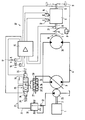
- FIG. 1 shows a hydraulic circuit diagram for the drive of a wheel loader.
- a transmission unit shown in the circuit diagram comprises an internal combustion engine as the drive motor 1, the drive shaft 2 of which drives the pump 3 of a hydrostatic transmission 4 with a closed circuit.
- a releasable coupling Between the output shaft 5 of the hydrostatic transmission 4 and a downstream two-speed manual transmission 6 there is a releasable coupling, generally designated 7, by means of which the output shaft 5 and the input shaft 8 of the manual transmission 6 can be connected or detached by an electromagnet 9.
- the coupling 7 is one that is rigid in the sense of a claw or bolt coupling.
- the output shaft of the manual transmission 6 connected in terms of drive to the wheels 11, which are indicated in the drawing, is designated by 12.
- the operation of the transmission unit is regulated by a control device (10) with an electronic control device 15, which is controlled by electrical lines with a switch 16 for the first or second gear of the manual transmission, with a switch 17 for forward and reverse travel, with the switching drives 13, 14, with the electromagnet 9, with two, the output shaft 5 of the hydrostatic transmission 4 and the input shaft 8 of the shift transmission 6 associated tachometers 19, 21 and in a manner yet to be described with an adjusting device generally designated 22 for the hydrostatic transmission 4.
- the hydrostatic transmission 4 is power-controlled by the adjusting device 22 as a function of the speed of the drive motor 1.
- the adjusting device 22 comprises an auxiliary pump 23, which is driven by the drive shaft 2 of the drive motor 1 and has a constant absorption volume, which is set up for operation in a conveying direction.
- the pump 3 of variable absorption volume, which is set up for operation in both conveying directions, is adjusted by a hydraulic cylinder 24, the double piston 26 of which is centered by springs 25 and which can be adjusted by optionally acting on the working spaces 27, 28.
- a directional control valve 29 is used, which connects the one or the other working space 27, 28 with a hydraulic line 31 into which the auxiliary pump 23 delivers by preselection of the forward or backward travel at the switch 17.
- a so-called pressure compensator is arranged in the hydraulic line 31, consisting of a throttle 32 in the hydraulic line 31 and a pressure control valve 33 arranged downstream of the latter, which can be adjusted in front of the throttle 32 by the working pressure in the hydraulic line 31.
- the switching magnets 34 for the directional control valve 29 can be both normal switching magnets and proportional magnets, which is shown by dash-dotted springs 35 against which the switching magnets 34 are effective.
- the respective adaptation of the output speed of the hydrostatic transmission 4 to the respective speed of the input shaft 8 can be done either by simple or by proportional adjustment of the directional valve 29 by the control device 10. It is essential that with the help of the control device 10 at the time of switching, or immediately thereafter, the above-described speed equality is achieved by appropriate control of the hydrostatic transmission. Before the preselection of the respective gear I, II and after the clutch 7 has been closed, there is no influence of the control device 10 on the adjusting device 22. As a result, the adjusting device 22 is only subject to the switching time, i. that is, when the circuit is initiated and carried out, the influence of the control device 10. Outside of the above-described functional section, the hydrostatic transmission 4 is power-controlled by the adjusting device 22 as a function of the speed of the drive motor 1.
- the invention is not restricted to the exemplary embodiment described above. Within the scope of the invention it is possible to use primary and / or secondary regulated hydrostatic transmissions.
- other active compounds can also be used, e.g. B. those in which the control device 10 acts specifically on the adjustment rod of the pump 3. In such a case, too, the control device 10 can act directly on the adjusting linkage or on an auxiliary drive for adjusting the hydrostatic transmission 4.
- the drive motor 1 simultaneously drives other units of the wheel loader, e.g. B. the lifting and swiveling device for the loading shovel. For reasons of simplification, this is not described and illustrated.
- a hydraulic action is also advantageously possible, for. B. by means of a pressure control valve in the hydraulic line 31, or in the main line of the hydrostatic transmission 4, which is controlled by a proportional magnet and can be connected to the electrical control device by an electrical line.
- control device adapts the output speed of the hydrostatic transmission to the speed change caused by the respective shift stage.
Abstract
Description
Die Erfindung bezieht sich auf eine Getriebeeinheit nach den Oberbegriff des Anspruchs 1.The invention relates to a gear unit according to the preamble of claim 1.
Getriebeeinheiten dieser Bauart sind in der Praxis eingeführt und bekannt. Es ist z. B. bei Radladern mit hydrostatischen Fahrantrieben bekannt, zur Vergrößerung des Geschwindigkeitsbereichs dem hydrostatischen Getriebe ein Schaltgetriebe nachzuordnen. Bei der bekannten Bauart ist das hydrostatische Getriebe in Abhängigkeit von der Drehzahl des Antriebsmotors leistungsgeregelt, um eine günstige Übertragung der Antriebskraft zu gewährleisten. Hierzu dient eine Verstelleinrichtung für das hydrostatische Getriebe, wie sie im Deutschen Patent 22 47 437 beschrieben und dargestellt ist. Eine willkürliche Verstellung des hydrostatischen Getriebes, d.h., eine willkürliche Verstellung seiner Ausgangsdrehzahl ist bei der bekannten Bauart unabhängig von der Drehzahl des Antriebsmotors nicht möglich.Gear units of this type have been introduced and are known in practice. It is Z. B. known in wheel loaders with hydrostatic travel drives to increase the speed range of the hydrostatic transmission a manual transmission. In the known design, the hydrostatic transmission is power-controlled as a function of the speed of the drive motor in order to ensure a favorable transmission of the drive force. For this purpose, an adjustment device for the hydrostatic transmission, as described and shown in
Infolgedessen bedarf es bei der bekannten Bauart einer Änderung der Antriebsmotordrehzahl, um das hydrostatische Getriebe an die durch die Schaltstufe bedingte Drehzahländerung anzupassen. Eine solche Drehzahlanpassung ist nicht nur deshalb nachteilig, weil sie eine hohe Aufmerksamkeit und Einfühlungsvermögen von der Bedienungsperson erfordert, sondern weil sie auch zu einem hohen Kraftstoffverbrauch und vorzeitigem Verschleiß führt.As a result, a change in the drive motor speed is required in the known design in order to adapt the hydrostatic transmission to the speed change caused by the shift stage. Such a speed adjustment is disadvantageous not only because it requires a high level of attention and empathy on the part of the operator, but also because it also leads to high fuel consumption and premature wear.
Darüberhinaus ergeben sich insbesondere bei verhältnismäßig großer Lastübertragung, wie es bei Baufahrzeugen z. B. Radladern, der Fall ist, Kupplungs- und Schaltschwierigkeiten, die durch die vorhandenen Schwungmassen bei gleichzeitiger verhältnismäßig großer Lastübertragung hervorgerufen werden. Ein Fahrantrieb in der bekannten Bauart für einen Radlader läßt sich deshalb praktisch nur bei Stillstand der Getriebeeinheit schalten.In addition, especially in relation moderately large load transfer, as is the case with construction vehicles, for. B. wheel loaders, the case is clutch and gearshift difficulties caused by the existing flywheels with a relatively large load transfer. A travel drive in the known design for a wheel loader can therefore be switched practically only when the gear unit is at a standstill.
Die bekannte Bauart ist insbesondere dann unzureichend, wenn der vorhandene Antriebsmotor mehrere Antriebsfunktionen gleichzeitig erfüllt, was bei Baufahrzeugen meistens gegeben ist. In einem solchen Fall ist durch zusätzliche Bauteile und Vorrichtungen dafür zu sorgen, daß die vom Antriebsmotor aufgrund höherer Drehzahlen (beim Herunterschalten) erbrachte Leistung den weiteren Verbrauchern nicht übertragen wird, weil diese sie beispielsweise nicht ausnutzen können. Andererseits würde durch eine Herabsetzung der Antriebsmotordrehzahl (beim Hochschalten) die Antriebsleistung auch für die anderen gleichzeitig angetriebenen Aggregate verringert werden, wodurch der Antrieb der anderen Aggregate beeinträchtigt werden würde.The known design is particularly inadequate when the existing drive motor fulfills several drive functions at the same time, which is usually the case with construction vehicles. In such a case, additional components and devices must be used to ensure that the power provided by the drive motor due to higher speeds (when shifting down) is not transmitted to the other consumers because, for example, they cannot use it. On the other hand, a reduction in the engine speed (when shifting up) would also reduce the drive power for the other simultaneously driven units, which would impair the drive of the other units.
Der Erfindung liegt die Aufgabe zugrunde, eine Getriebeeinheit der eingangs bezeichneten Bauart so auszugestalten, daß das Schaltgetriebe im Betrieb geschaltet werden kann.The invention has for its object to design a transmission unit of the type described above so that the manual transmission can be switched during operation.
Diese Aufgabe wird durch die im Anspruch 1 enthaltenen Merkmale gelöst. Der durch die Erfindung erzielbare wesentliche Vorteil besteht darin, daß die Ausgangsdrehzahl des hydrostatischen Getriebes unabhängig von der jeweiligen Drehzahl des Antriebsmotors manuell oder automatisch gezielt verändert werden kann. Die erfindungsgemäße Ausgestaltung ermöglicht beim Einsatz sowohl eines einfachen Schaltgetriebes als auch eines gemäß Anspruch 11 unter Last schaltbaren Getriebes einen einfachen Wechsel der Schaltstufen während des Betriebs des Antriebsmotors, ohne daß es einer Änderung bzw. Anpassung der Antriebsmotordrehzahl an die durch die Schaltstufe bedingte Drehzahländerung des Schaltgetriebes bedarf. Die Anpassung der durch das Schalten bedingten Drehzahländerung erfolgt innerhalb der Getriebeeinheit durch die Regeleinrichtung. Aufgrund dieser Drehzahlanpassung ist ein einfacher und ruckfreier Schaltvorgang möglich.This object is achieved by the features contained in claim 1. The essential advantage that can be achieved by the invention is that the output speed of the hydrostatic transmission can be changed manually or automatically, independently of the respective speed of the drive motor. The configuration according to the invention enables use Both a simple gearbox and a gearbox that can be shifted under load make it easy to change the gear stages during operation of the drive motor without requiring a change or adaptation of the engine speed to the speed change of the gearbox caused by the gear stage. The adjustment of the speed change caused by the switching takes place within the transmission unit by the control device. Due to this speed adjustment, a simple and smooth shifting process is possible.
Beim Einsatz eines einfachen Schaltgetriebes werden mittels der Regeleinrichtung die beiden miteinander zu verbindenden Getriebeteile (Kupplung) auf eine gleiche Drehzahl gebracht. Beim Einsatz eines Lastschaltgetriebes wird die Ausgangsdrehzahl des hydrostatischen Getriebes an die durch die Schaltstufe bedingte Drehzahländerung angepaßt.When using a simple manual transmission, the two transmission parts (clutch) to be connected to one another are brought to the same speed by means of the control device. When using a powershift transmission, the output speed of the hydrostatic transmission is adapted to the speed change caused by the gear shift.
Da bei der erfindungsgemäßen Ausgestaltung die jeweilige Leistung des Antriebsmotors aufgrund unabhängiger Antriebsmotordrehzahlen beim Schalten im wesentlichen unverändert bleibt, eignet sich die erfindungsgemäße Ausgestaltung insbesondere für solche Anordnungen, bei denen der Antriebsmotor mehrere Antriebsfunktionen gleichzeitig erfüllt. Durch die erfindungsgemäße Ausgestaltung werden die eingangs beschriebenen Nachteile (Kraftstoffverbrauch, Antriebsmotorleistungsveränderung) vermieden und der leistungsgerechte Betrieb der weiteren vom Antriebsmotor gleichzeitig angetriebenen Aggregate gewährleistet.Since in the embodiment according to the invention the respective power of the drive motor remains essentially unchanged due to independent drive motor speeds when switching, the embodiment according to the invention is particularly suitable for arrangements in which the drive motor fulfills several drive functions simultaneously. The configuration according to the invention avoids the disadvantages described at the outset (fuel consumption, drive motor output change) and ensures that the other units driven by the drive motor are operated in a manner appropriate to the output.
Die erfindungsgemäße Ausgestaltung stellt sich somit als ein zusätzliches Regulativ dar, das gemäß Anspruch 2 vorteilhaft in die Verstellvorrichtung für das hydrostatische Getriebe integriert werden kann, oder so angeordnet werdenkann, daß es auf die Verstellvorrichtung wirkt. In beiden Fällen können Bauteile eingespart werden, weil die Regeleinrichtung auf vorhandene Stellglieder wirkt und somit zusätzliche bzw. doppelte Stellglieder eingespart werden können. Dabei ist es natürlich von Vorteil, eine drehzahlabhängige Leistungsregelvorrichtung für das hydrostatische Getriebe gemäß Anspruch 8 vorzusehen, die an sich bekannt ist und auch eine Veränderung der Ausgangsdrehzahl des hydrostatischen Getriebes ermöglicht, jedoch in Abhängigkeit von der Funktion des Antriebsmotors. Bei der erfindungsgemäßen Weiterbildung wird somit die an sich bekannte Verstellvorrichtung für den erfindungsgemäßen Zweck ausgenutzt.The configuration according to the invention thus presents itself as an additional regulation, which according to
Im Anspruch 3 sind Einrichtungen aufgezählt, die eine sichere Funktion der erfindungsgemäßen Ausgestaltung gewährleisten. Sie umfassen zwei Meßeinrichtungen zur Ermittlung der Umfangsgeschwindigkeiten oder der Drehzahlen der miteinander zu verbindenden Getriebeteile, nämlich der vorhandenen Kupplung, und eine elektronische Steuereinrichtung, in der die Ergebnisse der Meßeinrichtungen verarbeitet werden und die bei Übereinstimmung der Umfangsgeschwindigkeiten oder Drehzahlen die Zusammenführbarkeit der Getriebeteile anzeigen oder die Zusammenführung einleiten kann. Eine Anzeige der Zusammenführbarkeit ermöglicht unter Ausnutzung der erfindungsgemäßen Vorteile eine manuelle Kupplung der Getriebeeinheit. Bei halb- oder vollautomatischen Betrieb erfolgt eine automatische Steuerung des Kupplungsvorganges.In
Im Rahmen der Erfindung ist es natürlich auch möglich, das Schalten, d. h. das Einlegen der Gänge automatisch zu steuern. Eine solche Funktion ermöglicht die Ausgestaltung nach Anspruch 4, bei der neben dem automatisch funktionierenden Schaltantrieb ein Schalter zur Wahl der Getriebegänge vorhanden ist.Within the scope of the invention it is of course also possible to automatically control the shifting, ie the engagement of the gears. Such a function enables the embodiment according to claim 4, in which in addition to the automatic functioning switching drive there is a switch for the selection of the transmission gears.
Bei der lösbaren Kupplung kann es sich um eine solche handeln, die innerhalb des Schaltgetriebes jeweils einer Schaltstufe zugeordnet ist, oder es kann sich auch um eine solche handeln, die gemäß Anspruch 7 zwischen dem hydrostatischen Getriebe und dem Schaltgetriebe angeordnet ist. Im ersten Fall bedarf es einer gleichen Umfangsgeschwindigkeit der miteinander zu verbindenden Kupplungsteile. Im zweiten Fall bedarf es einer gleichen Drehzahl.The releasable clutch can be one that is assigned to a shift stage within the manual transmission, or it can also be one that is arranged between the hydrostatic transmission and the manual transmission. In the first case, the same peripheral speed of the coupling parts to be connected to one another is required. In the second case, the same speed is required.
Die erfindungsgemäße Ausgestaltung bzw. Anordnung ermöglicht ein einfaches und ruckfreies Schalten auch beim Einsatz einer starr wirksamen Kupplung, z. B. einer Klauenkupplung, gemäß Anspruch 4, mit der insbesondere größere Antriebskräfte sicher übertragen werden können, wie es bei Antrieben für Baufahrzeuge oder vergleichbare Fahrzeuge und Maschinen gefordert ist.The design or arrangement according to the invention enables simple and jerk-free switching even when using a rigid coupling, z. B. a claw clutch, according to claim 4, with which in particular larger driving forces can be safely transmitted, as is required for drives for construction vehicles or comparable vehicles and machines.
Mit der Ausbildung gemäß Anspruch 9 wird von einer ebenfalls durch den eingangs beschriebenen Stand der Technik schon bekannten und bewährten Ausgestaltung bzw. Anordnung Gebrauch bemacht.With the design according to claim 9, use is made of a design or arrangement which is already known and proven by the prior art described at the outset.
Für die Einwirkung der Regeleinrichtung auf die Pumpe des hydrostatischen Getriebes oder auf dessen vorhandene Verstellvorrichtung gibt es mehrere Möglichkeiten. Bei einem gemäß dem eingangs beschriebenen Stand der Technik von einer Hilfspumpe beaufschlagten Stellglied ist es möglich, durch ein von der elektronischen Steuereinrichtung gesteuertes oder geregeltes Druckregelventil auf die Verstellvorrichtung einzuwirken. Es ist auch möglich, mit der Regeleinrichtung unmittelbar auf das Stellglied selbst oder auf Anbauteile desselben einzuwirken. Dabei empfiehlt sich ein proportionaler Betrieb, z. B. mittels Proportionalmagneten (Anspruch 10).There are several options for the action of the control device on the pump of the hydrostatic transmission or on its existing adjustment device. In the case of an actuator acted upon by an auxiliary pump in accordance with the prior art described at the outset, it is possible to act on the adjusting device by means of a pressure control valve which is controlled or regulated by the electronic control device. It is also possible to act directly on the actuator itself or on attachments thereof with the control device. Proportional operation is recommended e.g. B. by means of proportional magnets (claim 10).
Nachfolgend wird ein Ausführungsbeispiel der Erfindung anhand einer vereinfachten Zeichnung näher beschrieben. Die Zeichnung zeigt einen hydraulischen Schaltplan für den Fahrantrieb eines Radladers. Eine im Schaltplan dargestellte Getriebeeinheit umfaßt einen Verbrennungsmotor als Antriebsmotor 1, dessen Antriebswelle 2 die Pumpe 3 eines hydrostatischen Getriebes 4 mit geschlossenem Kreislauf antreibt. Zwischen der Ausgangswelle 5 des hydrostatischen Getriebes 4 und einem diesem nachgeordneten zweigängigen Schaltgetriebe 6 ist eine allgemein mit 7 bezeichnete lösbare Kupplung angeordnet, mit der die Ausgangswelle 5 und die Eingangswelle 8 des Schaltgetriebes 6 durch einen Elektromagneten 9 miteinander verbindbar oder lösbar sind. Bei der Kupplung 7 handelt es sich um eine solche, die im Sinne einer Klauen- bzw. Bolzenkupplung starr ist. Die antriebsmäßig mit den andeutungsweise dargestellten Rädern 11 verbundene Ausgangswelle des Schaltgetriebes 6 ist mit 12 bezeichnet.An exemplary embodiment of the invention is described in more detail below with the aid of a simplified drawing. The drawing shows a hydraulic circuit diagram for the drive of a wheel loader. A transmission unit shown in the circuit diagram comprises an internal combustion engine as the drive motor 1, the
Einzelheiten des Schaltgetriebes 6 sind nicht dargestellt. Es sind lediglich zwei Schaltantriebe 13, 14 sichtbar.Details of the manual transmission 6 are not shown. Only two
Der Betrieb der Getriebeeinheit wird durch eine Regeleinrichtung (10) mit einer elektronischen Steuereinrichtung 15 geregelt, die durch elektrische Leitungen mit einem Schalter 16 für den ersten oder zweiten Gang des Schaltgetriebes, mit einem Schalter 17 für Vorwärts- und Rückwärtsfahrt, mit den Schaltantrieben 13, 14, mit dem Elektromagneten 9, mit zwei, der Ausgangswelle 5 des hydrostatischen Getriebes 4 und der Eingangswelle 8 des Schältgetriebes 6 zugeordneten Drehzahlmessern 19, 21 und in noch zu beschreibender Weise mit einer allgemein mit 22 bezeichneten Verstellvorrichtung für das hydrostatische Getriebe 4 verbunden ist.The operation of the transmission unit is regulated by a control device (10) with an electronic control device 15, which is controlled by electrical lines with a
Das hydrostatische Getriebe 4 ist durch die Verstellvorrichtung 22 in Abhängigkeit von der Drehzahl des Antriebsmotors 1 leistungsgeregelt. Die Verstellvorrichtung 22 umfaßt eine durch die Antriebswelle 2 des Antriebsmotors 1 angetriebene Hilfspumpe 23 unveränderlichen Schluckvolumens, die für den Betrieb in eine Förderrichtung eingerichtet ist. Die Pumpe 3 veränderlichen Schluckvolumens, die für den Betrieb in beide Förderrichtungen eingerichtet ist, wird durch einen Hydraulikzylinder 24 verstellt, dessen durch Federn 25 mittelzentrierter Doppelkolben 26 durch wahlweise Beaufschlagung der Arbeitsräume 27, 28 verstellbar ist. Hierzu dient ein Wegeventil 29, das jeweils durch Vorwahl der Vorwärts- oder Rückwärtsfahrt am Schalter 17 den einen oder anderen Arbeitsraum 27, 28 mit einer Hydraulikleitung 31 verbindet, in die die Hilfspumpe 23 fördert. In der Hydraulikleitung 31 ist eine sogenannte Druckwaage angeordnet, bestehend aus einer Drossel 32 in der Hydraulikleitung 31, und einem dieser in Strömungsrichtung nachgeordneten Druckregelventil 33, das durch den Arbeitsdruck in der Hydraulikleitung 31 vor der Drossel 32 verstellbar ist.The hydrostatic transmission 4 is power-controlled by the adjusting
Bei den Schaltmagneten 34 für das Wegeventil 29 kann es sich sowohl um normale Schaltmagnete, als auch um Proportionalmagnete handeln, was durch strichpunktiert angedeutete Federn 35 dargestellt ist, gegen die die Schaltmagiete34 wirksam sind.The
Im folgenden wird die Funktion der Getriebeeinheit erklärt:
- Vor- oder Rückwärtsfahrt wird durch Vorwahl am
Schalter 17 vorgewählt. Die Schaltung des Schaltgetriebes 6 wird durch Vorwahl des beabsichtigten Ganges eingeleitet. Die beiden Gänge sind mit I und II bezeichnet. Wird z. B. bei Fahrt des Radladers im ersten Gang der zweite Gang vorgewählt, dann wird dasWegeventil 29 in die dargestellte Null-Stellung geschaltet, was eine automatische Verstellung derPumpe 3 in Richtung auf 0 bewirkt. Hierdurch wird dieKupplung 7 entlastet, was gegebenenfalls zusätzlich durch einen nicht dargestellten Druckvergleich vor und hinterdem Hydromotor 36 ermittelt werden kann. Ein solcher Druckschalter wäre ebenfalls mit der elektronischen Steuereinrichtung 15 zu verbinden. Anschließend erfolgt ein ruckfreies Entkuppeln der Kupplung 7,weil die Kupplung 7 entlastet ist. Nach dem Entkuppeln erfolgt die automatische Schaltung des Schaltgetriebes 6 in den zweiten Gang. Nunmehr werden mit Hilfe der Drehzahlmesser 19, 21 dieDrehzahlen der Ausgangswelle 5 und der Eingangswelle 8 miteinander verglichen. Je nach Fahrbetrieb kann das automatische weitere Zurückschwenken der Pumpe 3 in Richtung auf O dazu beitragen, daß sich eine gleiche Drehzahl ander Ausgangswelle 5 und der Eingangswelle 8 einstellt. Ist nach dem Schaltvorgang dieDrehzahl der Eingangswelle 8 größer als dieder Ausgangswelle 5, dann wird diePumpe 3 durch eine entsprechende Verstellung des Wegeventils 29 mittels der Regeleinrichtung 10 ausgeschwenkt, was eine Drehzahlerhöhung ander Ausgangswelle 5 bewirkt. Soblad Drehzahlgleichheit ander Ausgangswelle 5 und ander Eingangswelle 8 vorliegt, wird automatisch gekuppelt unddann das Wegeventil 29 wieder zurückgestellt.
- Forward or reverse travel is preselected by preselection at
switch 17. The shifting of the gearbox 6 is initiated by preselecting the intended gear. The two gears are labeled I and II. Is z. B. when the wheel loader is traveling in first gear, the second gear is preselected, then thedirectional control valve 29 is switched to the zero position shown, which causes thepump 3 to be automatically adjusted in the direction of 0. In this way, theclutch 7 is relieved, which can optionally be determined additionally by a pressure comparison, not shown, in front of and behind thehydraulic motor 36. Such a pressure switch would also have to be connected to the electronic control device 15. Theclutch 7 is then uncoupled uncoupled because theclutch 7 is relieved. After uncoupling, the automatic transmission 6 is shifted into second gear. The speeds of theoutput shaft 5 and theinput shaft 8 are now compared with one another with the aid of thetachometers pump 3 in the direction of O can contribute to the same speed being set on theoutput shaft 5 and theinput shaft 8. If the speed of theinput shaft 8 is greater than that of theoutput shaft 5 after the switching operation, then thepump 3 is pivoted out by a corresponding adjustment of thedirectional valve 29 by means of the control device 10, which causes an increase in speed on theoutput shaft 5. Soblad speed equality on theoutput shaft 5 and on theinput shaft 8 is automatically coupled and then thedirectional control valve 29 is reset.
Das Herunterschalten vom zweiten in den ersten Gang erfolgt in vergleichbarer Weise. Auch hier wird die Kupplung 7 in entlastetem Zustand gelöst, dann automatisch geschaltet und anschließend die Drehzahl der Ausgangswelle 5 durch von der Regeleinrichtung 10 gesteuertes Ausschwenken der Pumpe 3 an die Drehzahl der Eingangswelle 8 angepaßt. Sobald Drehzahlgleichheit vorliegt, wird die Kupplung 7 geschlossen.The downshift from second to first gear takes place in a comparable manner. Here, too, the
Das jeweilige Anpassen der Ausgnagsdrehzahl des hydrostatischen Getriebes 4 an die jeweilige Drehzahl der Eingangswelle 8 kann sowohl durch einfaches, als auch durch proportionales Verstellen des Wegeventils 29 durch die Regeleinrichtung 10 erfolgen. Von wesentlicher Bedeutung ist, daß mit Hilfe der Regeleinrichtung 10 zum Schaltzeitpunkt, bzw. unmittelbar danach die vorbeschriebene Drehzahlgleichheit durch entsprechende Regelung des hydrostatischen Getriebes erreicht wird. Vor der Vorwahl des jeweiligen Ganges I, II und nach dem Schließen der Kupplung 7 besteht kein Einfluß der Regeleinrichtung 10 auf die Verstellvorrichtung 22. Infolgedessen unterliegt die Verstellvorrichtung 22 nur zum Schaltzeitpunkt, d. h., bei Einleitung und Durchführung der Schaltung, dem Einfluß der Regeleinrichtung 10. Außerhalb des vorbeschriebenen Funktionsabschnitts ist das hydrostatische Getriebe 4 durch die Verstellvorrichtung 22 in Abhängigkeit von der Drehzahl des Antriebsmotors 1 leistungsgeregelt.The respective adaptation of the output speed of the hydrostatic transmission 4 to the respective speed of the
Die Erfindung ist nicht auf das vorbeschriebene Ausführungsbeispiel beschränkt. Im Rahmen der Erfindung ist es möglich, primär- und/oder sekundärgeregelte hydrostatische Getriebe einzusetzen. Darüberhinaus können auch andere Wirkverbindungen zum Einsatz kommen, z. B. solche, bei denen die Regeleinrichtung 10 eigens auf das Verstellgestänge der Pumpe 3 wirkt. Auch in einem solchen Fall kann die Regeleinrichtung 10 unmittelbar auf das Verstellgestänge wirken, oder auf einen Hilfsantrieb zur Verstellung des hydrostatischen Getriebes 4.The invention is not restricted to the exemplary embodiment described above. Within the scope of the invention it is possible to use primary and / or secondary regulated hydrostatic transmissions. In addition, other active compounds can also be used, e.g. B. those in which the control device 10 acts specifically on the adjustment rod of the
Der Antriebsmotor 1 treibt gleichzeitig weitere Aggregate des Radladers an, z. B. die Hub- und Schwenkeinrichtung für die Ladeschaufel. Dies ist aus Vereinfachungsgründen nicht beschrieben und dargestellt.The drive motor 1 simultaneously drives other units of the wheel loader, e.g. B. the lifting and swiveling device for the loading shovel. For reasons of simplification, this is not described and illustrated.
Anstelle einer mechanischen Einwirkung der Regeleinrichtung 10 auf die Verstellvorrichtung 22 ist auch eine hydraulische Einwirkung vorteilhaft möglich, z. B. mittels eines Druckregelventils in der Hydraulikleitung 31, oder in der Hauptleitung des hydrostatischen Getriebes 4, das von einem Proportionalmagneten gesteuert wird und durch eine elektrische Leitung mit der elektrischen Steuereinrichtung in Verbindung stehen kann.Instead of a mechanical action of the control device 10 on the adjusting
Im Rahmen der Erfindung ist es in vorteilhafter Weise auch möglich, anstelle des einfachen Schaltgetriebes 6 ein Lastschaltgetriebe vorzusehen. In diesem Fall erfolgt durch die Regeleinrichtung eine Anpassung der Ausgangsdrehzahl des hydrostatischen Getriebes an die durch die jeweilige Schaltstufe bedingte Drehzahländerung.In the context of the invention, it is also advantageously possible to provide a powershift transmission instead of the simple manual transmission 6. In this case, the control device adapts the output speed of the hydrostatic transmission to the speed change caused by the respective shift stage.
Claims (11)
dadurch gekennzeichnet,
daß dem hydrostatischen Getriebe (4) eine während des Schaltvorganges wirksame Regeleinrichtung (10) zwecks Anpassung der Ausgangsdrehzahl des hydrostatischen Getriebes (4) bzw. der Eingangsdrehzahl des Schaltgetriebes (6) an die durch die Schaltstufe bedingte Drehzahländerung zugeordnet ist.1. Transmission unit for a travel drive, consisting of an adjustable by means of an adjusting device, a pump and a hydraulic motor having hydrostatic transmission and a downstream transmission, preferably for machines and vehicles, especially construction vehicles, the drive motors fulfill several drive functions simultaneously, for. B. for wheel loaders,
characterized,
that the hydrostatic transmission (4) is associated with an effective control device (10) during the switching process for the purpose of adapting the output speed of the hydrostatic transmission (4) or the input speed of the manual transmission (6) to the speed change caused by the switching stage.
daß die Regeleinrichtung (10) in die Verstellvorrichtung. (22) integriert ist oder auf die Verstellvorrichtung (22) wirkt.2. Gear unit according to claim 1, characterized in
that the control device (10) in the adjusting device. (22) is integrated or acts on the adjusting device (22).
daß die Regeleinrichtung (10) Meßeinrichtungen (19, 21), die die Umfangsgeschwindigkeiten oder die Drehzahlen der miteinander zu verbindenden Getriebeteile (7) ermitteln, und eine elektronische Steuereinrichtung (15) umfaßt, die bei Übereinstimmung der Umfangsgeschwindigkeiten oder Drehzahlen die Zusammenführbarkeit der Getriebeteile (7) anzeigt oder die Zusammenführung einleitet.3. Gear unit according to claim 1 or 2, characterized in
that the control device (10) comprises measuring devices (19, 21) which determine the peripheral speeds or the speeds of the gear parts (7) to be connected to one another, and an electronic control device (15) which, if the peripheral speeds or speeds match, the mergability of the gear parts ( 7) displays or initiates the merge.
daß dem Schaltgetriebe (6) wenigstens ein automatischer Schaltantrieb (13, 14) zugeordnet ist, der von der elektrischen Steuereinrichtung (15) gesteuert wird, und daß ein Schalter (16) zur Wahl der Getriebegänge (1,11) vorgesehen ist.4. Gear unit according to one of claims 1 to 3, characterized in that
that the manual transmission (6) is assigned at least one automatic switching drive (13, 14) which is controlled by the electrical control device (15), and that a switch (16) is provided for selecting the transmission gears (1, 11).
daß die miteinander zu verbindenden Getriebeteile Teile einer Kupplung (7) sind.5. Gear unit according to one of claims 1 to 4, characterized in
that the gear parts to be connected are parts of a clutch (7).
daß die Kupplung (7) eine starr wirksame Kupplung, insbesondere eine Klauenkupplung ist.6. Gear unit according to one of claims 1 to 5, characterized in
that the coupling (7) is a rigid coupling, in particular a claw coupling.
daß die Kupplung (7) zwischen dem hydrostatischen Getriebe (4) und dem Schaltgetriebe (6) angeordnet ist.7. Gear unit according to claim 5 or 6, characterized in
that the clutch (7) is arranged between the hydrostatic transmission (4) and the manual transmission (6).
daß die Verstellvorrichtung (22) ein Stellglied (26) aufweist, dessen Verstellbewegung in Abhängigkeit von der Drehzahl des Antriebsmotors (1) leistungsgeregelt ist.8. Gear unit according to one of claims 1 to 7, characterized in
that the adjusting device (22) has an actuator (26), the adjusting movement of which is power-controlled as a function of the speed of the drive motor (1).
daß das Stellglied (26) ein vom Steuerdruck einer synchron zur Antriebsmotordrehzahl getriebenen Hilfspumpe (23) beaufschlagtes Stellglied (26) ist.9. Transmission unit according to claim 8, characterized in
that the actuator (26) is an actuator (26) acted upon by the control pressure of an auxiliary pump (23) driven synchronously with the drive motor speed.
daß die Regeleinrichtung (10) mit Hilfe wenigstens eines proportional wirksamen Verstellelements (34) im Rahmen eines Druckregelventils oder unmittelbar auf das Stellglied (26) einwirkt.10. Transmission unit according to one of claims 1 to 9, characterized in that
that the control device (10) acts with the aid of at least one proportionally effective adjusting element (34) in the context of a pressure control valve or directly on the actuator (26).
daß das Schaltgetriebe (6) ein unter Last schaltbares Getriebe ist.11. Gear unit according to one of claims 1 to 10, characterized
that the manual transmission (6) is a switchable under load.
Applications Claiming Priority (2)
| Application Number | Priority Date | Filing Date | Title |
|---|---|---|---|
| DE3433495 | 1984-09-12 | ||
| DE19843433495 DE3433495A1 (en) | 1984-09-12 | 1984-09-12 | TRANSMISSION UNIT FOR A TRAVEL DRIVE, CONSISTING OF AN ADJUSTABLE HYDROSTATIC TRANSMISSION AND A POST-GEARBOX TRANSMISSION |
Publications (3)
| Publication Number | Publication Date |
|---|---|
| EP0175192A1 true EP0175192A1 (en) | 1986-03-26 |
| EP0175192B1 EP0175192B1 (en) | 1989-03-08 |
| EP0175192B2 EP0175192B2 (en) | 1994-06-01 |
Family
ID=6245227
Family Applications (1)
| Application Number | Title | Priority Date | Filing Date |
|---|---|---|---|
| EP85110959A Expired - Lifetime EP0175192B2 (en) | 1984-09-12 | 1985-08-30 | Drive unit for vehicle propulsion consisting of a variable hydrostatic transmission followed by a gearbox |
Country Status (2)
| Country | Link |
|---|---|
| EP (1) | EP0175192B2 (en) |
| DE (2) | DE3433495A1 (en) |
Cited By (6)
| Publication number | Priority date | Publication date | Assignee | Title |
|---|---|---|---|---|
| EP0282010A2 (en) * | 1987-03-09 | 1988-09-14 | Hydromatik GmbH | Driving device consisting of a motor with changing numbers of revolution, a variable hydrostatic transmission and a shifting device |
| EP0339346A1 (en) * | 1988-04-27 | 1989-11-02 | CLARK-HURTH COMPONENTS S.p.A. | Automatic control device for the gearshift of industrial vehicles |
| FR2669093A1 (en) * | 1990-11-12 | 1992-05-15 | Saherrera | Device for allowing a hydrostatic translation of a motorised craft equipped with a mechanical transmission |
| US5329828A (en) * | 1990-07-25 | 1994-07-19 | Clark-Hurth Components S.P.A. | Three-shaft gearbox with dual input motors |
| US5388450A (en) * | 1991-03-15 | 1995-02-14 | Clark-Hurth Components S.P.A. | Gearbox with hydrostatic motors particularly for earth-movers |
| CN102416867A (en) * | 2011-10-31 | 2012-04-18 | 中联重科股份有限公司 | Double power drive device for engineering machine |
Families Citing this family (13)
| Publication number | Priority date | Publication date | Assignee | Title |
|---|---|---|---|---|
| DE3807599A1 (en) * | 1988-03-08 | 1989-09-28 | Hydromatik Gmbh | AUTOMOTIVE DRIVE DEVICE FOR MACHINES AND VEHICLES |
| DE4340126C2 (en) * | 1993-11-25 | 1997-03-20 | Detlef Tolksdorf | Electro-hydraulic control for power shift transmissions in vehicles |
| DE19524189C2 (en) * | 1995-07-03 | 1997-07-17 | Brueninghaus Hydromatik Gmbh | Hydrostatic drive with downstream powershift transmission |
| KR100446686B1 (en) * | 1997-05-31 | 2004-10-14 | 볼보 컨스트럭션 이키프먼트 홀딩 스웨덴 에이비 | Automatic transmission and method |
| DE102013008792B4 (en) | 2013-05-23 | 2016-12-22 | Thomas Magnete Gmbh | Method and device for adjusting a hydraulic variable displacement pump |
| CN105065611A (en) * | 2015-07-16 | 2015-11-18 | 河海大学常州校区 | Hydraulic coupler |
| CN104976301A (en) * | 2015-07-16 | 2015-10-14 | 河海大学常州校区 | Hydraulic coupler |
| CN104930154A (en) * | 2015-07-16 | 2015-09-23 | 河海大学常州校区 | Hydraulic coupler |
| CN105065612A (en) * | 2015-07-16 | 2015-11-18 | 河海大学常州校区 | Hydraulic coupler |
| CN105065607A (en) * | 2015-07-16 | 2015-11-18 | 河海大学常州校区 | Hydraulic coupler |
| CN105179514A (en) * | 2015-07-16 | 2015-12-23 | 河海大学常州校区 | Hydraulic coupler |
| CN104976302A (en) * | 2015-07-16 | 2015-10-14 | 河海大学常州校区 | Hydraulic coupler |
| CN105065608A (en) * | 2015-07-16 | 2015-11-18 | 河海大学常州校区 | Hydraulic coupler |
Citations (6)
| Publication number | Priority date | Publication date | Assignee | Title |
|---|---|---|---|---|
| DE1580249A1 (en) * | 1965-12-18 | 1970-01-29 | Lucas Industries Ltd | Control of hydraulic power transmission systems for vehicles |
| DE2237595B1 (en) * | 1972-07-31 | 1973-10-25 | Hydromatik Gmbh, 7900 Ulm | TRANSMISSION ADJUSTMENT FOR A COMPOSITE TRANSMISSION CONSISTING OF AN ADJUSTABLE HYDROSTATIC GEAR UNIT AND A SUBSEQUENT MECHANICAL POWER SHIFT TRANSMISSION |
| DE2307550A1 (en) * | 1973-02-16 | 1974-08-22 | Zahnradfabrik Friedrichshafen | SHIFTING ARRANGEMENT FOR A HYDRAULIC GEARBOX AND ADDITIONAL GEARBOX |
| DE2652976A1 (en) * | 1976-11-22 | 1978-05-24 | Linde Ag | Torque control for automatic transmission - has fixed ratio gear box and hydrostatic train to extend ratio range |
| GB1590981A (en) * | 1977-11-02 | 1981-06-10 | Zahnradfabrik Friedrichshafen | Hydromechanical transmission and controls |
| WO1984001419A1 (en) * | 1982-09-29 | 1984-04-12 | Zahnradfabrik Friedrichshafen | Hydrostatic driving device |
Family Cites Families (5)
| Publication number | Priority date | Publication date | Assignee | Title |
|---|---|---|---|---|
| DE2165527C3 (en) * | 1971-12-30 | 1978-12-07 | Kloeckner-Humboldt-Deutz Ag, 5000 Koeln | Control device for a hydrostatic transmission for motor vehicles |
| GB1525861A (en) * | 1975-10-23 | 1978-09-20 | Mullard Ltd | Vehicle power transmission arrangements and electronic control means therefor |
| DE2629977C3 (en) * | 1976-07-03 | 1978-12-14 | Zahnradfabrik Friedrichshafen Ag, 7990 Friedrichshafen | Hydrostatic converter with a hydraulic motor, a hydraulic pump and a downstream powershift transmission |
| DE2656976A1 (en) * | 1976-12-16 | 1978-06-29 | Bosch Gmbh Robert | DC regulator for generators driven by IC engines - has diode in series with threshold switch reducing switch response voltage |
| US4262335A (en) * | 1978-08-18 | 1981-04-14 | S.R.M. Hydromekanik | Vehicle transmission control system |
-
1984
- 1984-09-12 DE DE19843433495 patent/DE3433495A1/en active Granted
-
1985
- 1985-08-30 EP EP85110959A patent/EP0175192B2/en not_active Expired - Lifetime
- 1985-08-30 DE DE8585110959T patent/DE3568555D1/en not_active Expired
Patent Citations (6)
| Publication number | Priority date | Publication date | Assignee | Title |
|---|---|---|---|---|
| DE1580249A1 (en) * | 1965-12-18 | 1970-01-29 | Lucas Industries Ltd | Control of hydraulic power transmission systems for vehicles |
| DE2237595B1 (en) * | 1972-07-31 | 1973-10-25 | Hydromatik Gmbh, 7900 Ulm | TRANSMISSION ADJUSTMENT FOR A COMPOSITE TRANSMISSION CONSISTING OF AN ADJUSTABLE HYDROSTATIC GEAR UNIT AND A SUBSEQUENT MECHANICAL POWER SHIFT TRANSMISSION |
| DE2307550A1 (en) * | 1973-02-16 | 1974-08-22 | Zahnradfabrik Friedrichshafen | SHIFTING ARRANGEMENT FOR A HYDRAULIC GEARBOX AND ADDITIONAL GEARBOX |
| DE2652976A1 (en) * | 1976-11-22 | 1978-05-24 | Linde Ag | Torque control for automatic transmission - has fixed ratio gear box and hydrostatic train to extend ratio range |
| GB1590981A (en) * | 1977-11-02 | 1981-06-10 | Zahnradfabrik Friedrichshafen | Hydromechanical transmission and controls |
| WO1984001419A1 (en) * | 1982-09-29 | 1984-04-12 | Zahnradfabrik Friedrichshafen | Hydrostatic driving device |
Cited By (8)
| Publication number | Priority date | Publication date | Assignee | Title |
|---|---|---|---|---|
| EP0282010A2 (en) * | 1987-03-09 | 1988-09-14 | Hydromatik GmbH | Driving device consisting of a motor with changing numbers of revolution, a variable hydrostatic transmission and a shifting device |
| EP0282010A3 (en) * | 1987-03-09 | 1990-05-09 | Hydromatik Gmbh | Driving device consisting of a motor with changing numbers of revolution, a variable hydrostatic transmission and a shifting device |
| EP0339346A1 (en) * | 1988-04-27 | 1989-11-02 | CLARK-HURTH COMPONENTS S.p.A. | Automatic control device for the gearshift of industrial vehicles |
| US4991465A (en) * | 1988-04-27 | 1991-02-12 | Hurth Axle S.P.A. | Automatic control device for the gearshift of industrial vehicles |
| US5329828A (en) * | 1990-07-25 | 1994-07-19 | Clark-Hurth Components S.P.A. | Three-shaft gearbox with dual input motors |
| FR2669093A1 (en) * | 1990-11-12 | 1992-05-15 | Saherrera | Device for allowing a hydrostatic translation of a motorised craft equipped with a mechanical transmission |
| US5388450A (en) * | 1991-03-15 | 1995-02-14 | Clark-Hurth Components S.P.A. | Gearbox with hydrostatic motors particularly for earth-movers |
| CN102416867A (en) * | 2011-10-31 | 2012-04-18 | 中联重科股份有限公司 | Double power drive device for engineering machine |
Also Published As
| Publication number | Publication date |
|---|---|
| DE3568555D1 (en) | 1989-04-13 |
| DE3433495C2 (en) | 1989-09-07 |
| EP0175192B1 (en) | 1989-03-08 |
| EP0175192B2 (en) | 1994-06-01 |
| DE3433495A1 (en) | 1986-03-20 |
Similar Documents
| Publication | Publication Date | Title |
|---|---|---|
| EP0175192B1 (en) | Drive unit for vehicle propulsion consisting of a variable hydrostatic transmission followed by a gearbox | |
| EP0282010B1 (en) | Driving device consisting of a motor with changing numbers of revolution, a variable hydrostatic transmission and a shifting device | |
| EP0339202B1 (en) | Driving device for machines and vehicles | |
| EP0716248A1 (en) | Power shift gearing with five-shaft orbital transmission | |
| DE3627611A1 (en) | CONTROL DEVICE FOR AN AUTOMATIC TRANSMISSION | |
| EP0174560B2 (en) | Propulsion device for machines and vehicles, especially for construction vehicles, e.g. a shovel loader | |
| DE2925353A1 (en) | AGRICULTURAL TRACTOR | |
| EP0140046B1 (en) | Hydrostatic-mechanical transmission arrangement | |
| EP0236322B1 (en) | Control device for a pressure-actuated coupling clutch | |
| DE2447950C2 (en) | ||
| DE4025069C1 (en) | ||
| DE102006008749A1 (en) | Hybrid drive unit for motorized vehicle has electronic control unit arranged to set second input shaft at suitable revs for relevant gear | |
| EP3308992A1 (en) | Pto shaft transmission | |
| DE884139C (en) | Gear change gears, especially for earthmoving equipment and road construction machines | |
| EP0890045B1 (en) | Gear control method for reducing the thermal stress on switching components in a reversing gear | |
| DE1002635C2 (en) | Gear change transmission for all-terrain vehicles | |
| EP0310873A1 (en) | Drive transmission for a commercial vehicle | |
| DE2065300B2 (en) | Reversing control for tractor transmission - has separate reversing gears to provide selection independent of forward ratios | |
| DE19936290B4 (en) | Drivetrain with transmission control and control elements for a work vehicle | |
| DE102019205231A1 (en) | Travel drive system for work machine | |
| DE3606460A1 (en) | Power shift transmission | |
| DE102019112157A1 (en) | PTO assembly | |
| DE1174177B (en) | Motor vehicle engine, preferably for agricultural towing vehicles | |
| DE2343743C2 (en) | Gear change gears in group construction, in particular for motor vehicles that can be used in agriculture and / or construction | |
| DE3902034C1 (en) | Driving arrangement for a vehicle |
Legal Events
| Date | Code | Title | Description |
|---|---|---|---|
| PUAI | Public reference made under article 153(3) epc to a published international application that has entered the european phase |
Free format text: ORIGINAL CODE: 0009012 |
|
| AK | Designated contracting states |
Kind code of ref document: A1 Designated state(s): DE FR GB IT |
|
| 17P | Request for examination filed |
Effective date: 19860902 |
|
| 17Q | First examination report despatched |
Effective date: 19871111 |
|
| GRAA | (expected) grant |
Free format text: ORIGINAL CODE: 0009210 |
|
| AK | Designated contracting states |
Kind code of ref document: B1 Designated state(s): DE FR GB IT |
|
| ITF | It: translation for a ep patent filed |
Owner name: JACOBACCI & PERANI S.P.A. |
|
| GBT | Gb: translation of ep patent filed (gb section 77(6)(a)/1977) | ||
| REF | Corresponds to: |
Ref document number: 3568555 Country of ref document: DE Date of ref document: 19890413 |
|
| ET | Fr: translation filed | ||
| PLBI | Opposition filed |
Free format text: ORIGINAL CODE: 0009260 |
|
| 26 | Opposition filed |
Opponent name: ZAHNRADFABRIK FRIEDRICHSHAFEN AKTIENGESELLSCHAFT Effective date: 19891207 Opponent name: LINDE AKTIENGESELLSCHAFT, WIESBADEN Effective date: 19891206 |
|
| ITTA | It: last paid annual fee | ||
| PUAH | Patent maintained in amended form |
Free format text: ORIGINAL CODE: 0009272 |
|
| STAA | Information on the status of an ep patent application or granted ep patent |
Free format text: STATUS: PATENT MAINTAINED AS AMENDED |
|
| 27A | Patent maintained in amended form |
Effective date: 19940601 |
|
| AK | Designated contracting states |
Kind code of ref document: B2 Designated state(s): DE FR GB IT |
|
| ITF | It: translation for a ep patent filed |
Owner name: JACOBACCI CASETTA & PERANI S.P.A. |
|
| GBTA | Gb: translation of amended ep patent filed (gb section 77(6)(b)/1977) |
Effective date: 19940817 |
|
| ET3 | Fr: translation filed ** decision concerning opposition | ||
| REG | Reference to a national code |
Ref country code: GB Ref legal event code: IF02 |
|
| PGFP | Annual fee paid to national office [announced via postgrant information from national office to epo] |
Ref country code: GB Payment date: 20040730 Year of fee payment: 20 |
|
| PGFP | Annual fee paid to national office [announced via postgrant information from national office to epo] |
Ref country code: DE Payment date: 20040805 Year of fee payment: 20 |
|
| PGFP | Annual fee paid to national office [announced via postgrant information from national office to epo] |
Ref country code: FR Payment date: 20040809 Year of fee payment: 20 |
|
| PG25 | Lapsed in a contracting state [announced via postgrant information from national office to epo] |
Ref country code: GB Free format text: LAPSE BECAUSE OF EXPIRATION OF PROTECTION Effective date: 20050829 |
|
| REG | Reference to a national code |
Ref country code: GB Ref legal event code: PE20 |
|
| APAH | Appeal reference modified |
Free format text: ORIGINAL CODE: EPIDOSCREFNO |