EP3308992A1 - Pto shaft transmission - Google Patents
Pto shaft transmission Download PDFInfo
- Publication number
- EP3308992A1 EP3308992A1 EP17196168.3A EP17196168A EP3308992A1 EP 3308992 A1 EP3308992 A1 EP 3308992A1 EP 17196168 A EP17196168 A EP 17196168A EP 3308992 A1 EP3308992 A1 EP 3308992A1
- Authority
- EP
- European Patent Office
- Prior art keywords
- output shaft
- shaft
- gear
- gears
- pto
- Prior art date
- Legal status (The legal status is an assumption and is not a legal conclusion. Google has not performed a legal analysis and makes no representation as to the accuracy of the status listed.)
- Withdrawn
Links
Images


Classifications
-
- B—PERFORMING OPERATIONS; TRANSPORTING
- B60—VEHICLES IN GENERAL
- B60K—ARRANGEMENT OR MOUNTING OF PROPULSION UNITS OR OF TRANSMISSIONS IN VEHICLES; ARRANGEMENT OR MOUNTING OF PLURAL DIVERSE PRIME-MOVERS IN VEHICLES; AUXILIARY DRIVES FOR VEHICLES; INSTRUMENTATION OR DASHBOARDS FOR VEHICLES; ARRANGEMENTS IN CONNECTION WITH COOLING, AIR INTAKE, GAS EXHAUST OR FUEL SUPPLY OF PROPULSION UNITS IN VEHICLES
- B60K17/00—Arrangement or mounting of transmissions in vehicles
- B60K17/28—Arrangement or mounting of transmissions in vehicles characterised by arrangement, location, or type of power take-off
-
- B—PERFORMING OPERATIONS; TRANSPORTING
- B60—VEHICLES IN GENERAL
- B60K—ARRANGEMENT OR MOUNTING OF PROPULSION UNITS OR OF TRANSMISSIONS IN VEHICLES; ARRANGEMENT OR MOUNTING OF PLURAL DIVERSE PRIME-MOVERS IN VEHICLES; AUXILIARY DRIVES FOR VEHICLES; INSTRUMENTATION OR DASHBOARDS FOR VEHICLES; ARRANGEMENTS IN CONNECTION WITH COOLING, AIR INTAKE, GAS EXHAUST OR FUEL SUPPLY OF PROPULSION UNITS IN VEHICLES
- B60K25/00—Auxiliary drives
- B60K25/06—Auxiliary drives from the transmission power take-off
-
- B—PERFORMING OPERATIONS; TRANSPORTING
- B60—VEHICLES IN GENERAL
- B60W—CONJOINT CONTROL OF VEHICLE SUB-UNITS OF DIFFERENT TYPE OR DIFFERENT FUNCTION; CONTROL SYSTEMS SPECIALLY ADAPTED FOR HYBRID VEHICLES; ROAD VEHICLE DRIVE CONTROL SYSTEMS FOR PURPOSES NOT RELATED TO THE CONTROL OF A PARTICULAR SUB-UNIT
- B60W30/00—Purposes of road vehicle drive control systems not related to the control of a particular sub-unit, e.g. of systems using conjoint control of vehicle sub-units, or advanced driver assistance systems for ensuring comfort, stability and safety or drive control systems for propelling or retarding the vehicle
- B60W30/18—Propelling the vehicle
- B60W30/188—Controlling power parameters of the driveline, e.g. determining the required power
- B60W30/1886—Controlling power supply to auxiliary devices
- B60W30/1888—Control of power take off [PTO]
-
- F—MECHANICAL ENGINEERING; LIGHTING; HEATING; WEAPONS; BLASTING
- F02—COMBUSTION ENGINES; HOT-GAS OR COMBUSTION-PRODUCT ENGINE PLANTS
- F02D—CONTROLLING COMBUSTION ENGINES
- F02D41/00—Electrical control of supply of combustible mixture or its constituents
- F02D41/02—Circuit arrangements for generating control signals
- F02D41/0205—Circuit arrangements for generating control signals using an auxiliary engine speed control
-
- F—MECHANICAL ENGINEERING; LIGHTING; HEATING; WEAPONS; BLASTING
- F16—ENGINEERING ELEMENTS AND UNITS; GENERAL MEASURES FOR PRODUCING AND MAINTAINING EFFECTIVE FUNCTIONING OF MACHINES OR INSTALLATIONS; THERMAL INSULATION IN GENERAL
- F16H—GEARING
- F16H3/00—Toothed gearings for conveying rotary motion with variable gear ratio or for reversing rotary motion
- F16H3/02—Toothed gearings for conveying rotary motion with variable gear ratio or for reversing rotary motion without gears having orbital motion
- F16H3/08—Toothed gearings for conveying rotary motion with variable gear ratio or for reversing rotary motion without gears having orbital motion exclusively or essentially with continuously meshing gears, that can be disengaged from their shafts
- F16H3/085—Toothed gearings for conveying rotary motion with variable gear ratio or for reversing rotary motion without gears having orbital motion exclusively or essentially with continuously meshing gears, that can be disengaged from their shafts with more than one output shaft
-
- F—MECHANICAL ENGINEERING; LIGHTING; HEATING; WEAPONS; BLASTING
- F16—ENGINEERING ELEMENTS AND UNITS; GENERAL MEASURES FOR PRODUCING AND MAINTAINING EFFECTIVE FUNCTIONING OF MACHINES OR INSTALLATIONS; THERMAL INSULATION IN GENERAL
- F16H—GEARING
- F16H3/00—Toothed gearings for conveying rotary motion with variable gear ratio or for reversing rotary motion
- F16H3/02—Toothed gearings for conveying rotary motion with variable gear ratio or for reversing rotary motion without gears having orbital motion
- F16H3/08—Toothed gearings for conveying rotary motion with variable gear ratio or for reversing rotary motion without gears having orbital motion exclusively or essentially with continuously meshing gears, that can be disengaged from their shafts
- F16H3/087—Toothed gearings for conveying rotary motion with variable gear ratio or for reversing rotary motion without gears having orbital motion exclusively or essentially with continuously meshing gears, that can be disengaged from their shafts characterised by the disposition of the gears
- F16H3/091—Toothed gearings for conveying rotary motion with variable gear ratio or for reversing rotary motion without gears having orbital motion exclusively or essentially with continuously meshing gears, that can be disengaged from their shafts characterised by the disposition of the gears including a single countershaft
-
- F—MECHANICAL ENGINEERING; LIGHTING; HEATING; WEAPONS; BLASTING
- F16—ENGINEERING ELEMENTS AND UNITS; GENERAL MEASURES FOR PRODUCING AND MAINTAINING EFFECTIVE FUNCTIONING OF MACHINES OR INSTALLATIONS; THERMAL INSULATION IN GENERAL
- F16H—GEARING
- F16H3/00—Toothed gearings for conveying rotary motion with variable gear ratio or for reversing rotary motion
- F16H3/02—Toothed gearings for conveying rotary motion with variable gear ratio or for reversing rotary motion without gears having orbital motion
- F16H3/08—Toothed gearings for conveying rotary motion with variable gear ratio or for reversing rotary motion without gears having orbital motion exclusively or essentially with continuously meshing gears, that can be disengaged from their shafts
- F16H3/087—Toothed gearings for conveying rotary motion with variable gear ratio or for reversing rotary motion without gears having orbital motion exclusively or essentially with continuously meshing gears, that can be disengaged from their shafts characterised by the disposition of the gears
- F16H3/093—Toothed gearings for conveying rotary motion with variable gear ratio or for reversing rotary motion without gears having orbital motion exclusively or essentially with continuously meshing gears, that can be disengaged from their shafts characterised by the disposition of the gears with two or more countershafts
-
- B—PERFORMING OPERATIONS; TRANSPORTING
- B60—VEHICLES IN GENERAL
- B60Y—INDEXING SCHEME RELATING TO ASPECTS CROSS-CUTTING VEHICLE TECHNOLOGY
- B60Y2200/00—Type of vehicle
- B60Y2200/20—Off-Road Vehicles
- B60Y2200/22—Agricultural vehicles
- B60Y2200/221—Tractors
-
- B—PERFORMING OPERATIONS; TRANSPORTING
- B60—VEHICLES IN GENERAL
- B60Y—INDEXING SCHEME RELATING TO ASPECTS CROSS-CUTTING VEHICLE TECHNOLOGY
- B60Y2400/00—Special features of vehicle units
- B60Y2400/42—Clutches or brakes
- B60Y2400/424—Friction clutches
- B60Y2400/4244—Friction clutches of wet type, e.g. using multiple lamellae
-
- F—MECHANICAL ENGINEERING; LIGHTING; HEATING; WEAPONS; BLASTING
- F16—ENGINEERING ELEMENTS AND UNITS; GENERAL MEASURES FOR PRODUCING AND MAINTAINING EFFECTIVE FUNCTIONING OF MACHINES OR INSTALLATIONS; THERMAL INSULATION IN GENERAL
- F16H—GEARING
- F16H37/00—Combinations of mechanical gearings, not provided for in groups F16H1/00 - F16H35/00
- F16H37/02—Combinations of mechanical gearings, not provided for in groups F16H1/00 - F16H35/00 comprising essentially only toothed or friction gearings
- F16H37/04—Combinations of toothed gearings only
- F16H37/042—Combinations of toothed gearings only change gear transmissions in group arrangement
- F16H37/043—Combinations of toothed gearings only change gear transmissions in group arrangement without gears having orbital motion
- F16H2037/045—Combinations of toothed gearings only change gear transmissions in group arrangement without gears having orbital motion comprising a separate gearing unit for shifting between high and low ratio range
-
- F—MECHANICAL ENGINEERING; LIGHTING; HEATING; WEAPONS; BLASTING
- F16—ENGINEERING ELEMENTS AND UNITS; GENERAL MEASURES FOR PRODUCING AND MAINTAINING EFFECTIVE FUNCTIONING OF MACHINES OR INSTALLATIONS; THERMAL INSULATION IN GENERAL
- F16H—GEARING
- F16H2200/00—Transmissions for multiple ratios
- F16H2200/003—Transmissions for multiple ratios characterised by the number of forward speeds
- F16H2200/0043—Transmissions for multiple ratios characterised by the number of forward speeds the gear ratios comprising four forward speeds
-
- F—MECHANICAL ENGINEERING; LIGHTING; HEATING; WEAPONS; BLASTING
- F16—ENGINEERING ELEMENTS AND UNITS; GENERAL MEASURES FOR PRODUCING AND MAINTAINING EFFECTIVE FUNCTIONING OF MACHINES OR INSTALLATIONS; THERMAL INSULATION IN GENERAL
- F16H—GEARING
- F16H59/00—Control inputs to control units of change-speed-, or reversing-gearings for conveying rotary motion
- F16H59/02—Selector apparatus
-
- F—MECHANICAL ENGINEERING; LIGHTING; HEATING; WEAPONS; BLASTING
- F16—ENGINEERING ELEMENTS AND UNITS; GENERAL MEASURES FOR PRODUCING AND MAINTAINING EFFECTIVE FUNCTIONING OF MACHINES OR INSTALLATIONS; THERMAL INSULATION IN GENERAL
- F16H—GEARING
- F16H61/00—Control functions within control units of change-speed- or reversing-gearings for conveying rotary motion ; Control of exclusively fluid gearing, friction gearing, gearings with endless flexible members or other particular types of gearing
- F16H61/02—Control functions within control units of change-speed- or reversing-gearings for conveying rotary motion ; Control of exclusively fluid gearing, friction gearing, gearings with endless flexible members or other particular types of gearing characterised by the signals used
- F16H61/0202—Control functions within control units of change-speed- or reversing-gearings for conveying rotary motion ; Control of exclusively fluid gearing, friction gearing, gearings with endless flexible members or other particular types of gearing characterised by the signals used the signals being electric
- F16H61/0204—Control functions within control units of change-speed- or reversing-gearings for conveying rotary motion ; Control of exclusively fluid gearing, friction gearing, gearings with endless flexible members or other particular types of gearing characterised by the signals used the signals being electric for gearshift control, e.g. control functions for performing shifting or generation of shift signal
- F16H61/0213—Control functions within control units of change-speed- or reversing-gearings for conveying rotary motion ; Control of exclusively fluid gearing, friction gearing, gearings with endless flexible members or other particular types of gearing characterised by the signals used the signals being electric for gearshift control, e.g. control functions for performing shifting or generation of shift signal characterised by the method for generating shift signals
Definitions
- the present invention relates to a transmission for a power output shaft on agricultural vehicles and a method for controlling the same.
- power output shafts are provided at the front and rear ends of agricultural vehicles.
- the output shaft also referred to as PTO, is used to supply attached units that are used in field work.
- the units may require different drive torques and speeds. For this reason, PTO are known to provide different speeds.
- the known power take-off gearboxes allow a switchover of the operating modes of the PTO shaft in the load-free state.
- the usual speeds of the PTO are 540 and 1000 revolutions per minute.
- gears which have the same rotational speed but can be operated with a low driving power of the agricultural vehicle. This allows the saving of fuel or drive energy.
- the present invention according to claim 1, a power take-off, with a PTO control, an input shaft, a first output shaft, a parallel intermediate shaft, a second output shaft, which is arranged coaxially to the first output shaft, four gear pairs, which are arranged such that the input shaft two gears, the first output shaft three gears, the intermediate shaft two gears and the second output shaft has a gear, so that two pairs of gears between the input shaft and the first output shaft, a pair of gears between the first output shaft and the intermediate shaft and a pair of gears between the intermediate shaft and the second output shaft are engaged, wherein at least one gear per gear pair is switchable.
- the PTO provides four gears that allow different speeds and / or different powers for the PTO in operation.
- a compact PTO gearbox will be provided.
- an adapted shift strategy can be realized, wherein the gears optionally have a freewheel through the shiftable gears, or are connected to the respective shaft. In neutral position, the gears thus run free and transfer no power.
- multi-disc clutches or jaw clutches come into consideration for switching the gears.
- Multi-disc clutches allow the shifting process under applied load, so that impacts in the power path are avoided.
- Jaw clutches require relieving the power path for shifting, but allow for a design with less space than a multi-plate clutch.
- the input shaft may comprise at least one switching element, and the first output shaft having at most two switching elements, with which the gears are switchable.
- the arrangement of the switching elements makes it possible to connect the gears rotatably with their respective shaft or to operate them in the freewheel. In an arrangement that operates two gears with a switching element, a compact design can be realized. It is possible to switch both gear pairs on the input shaft through a switching element, as well as on the first output shaft.
- the intermediate shaft can have no switching element and can be realized with a smaller space.
- the input shaft with the first output shaft be connectable, and be connected by the at most two switching elements of the first output shaft, the first output shaft with the input shaft and the second output shaft, or the input shaft with the first output shaft, the intermediate shaft and the second output shaft be connectable.
- the supply of the PTO shaft with drive energy takes place via the second output shaft.
- the switching elements can be switched between the two gear pairs of the input shaft and between the power path that leads directly from the first to the second output shaft, or from the first output shaft via the intermediate shaft to the second output shaft.
- Another embodiment relates to a PTO with a PTO control, a first input shaft, a second input shaft, a first output shaft, a parallel intermediate shaft, a second output shaft, which is arranged coaxially to the first output shaft, four gear pairs, which are arranged such that the second Input shaft two gears, the first output shaft three gears, the intermediate shaft two gears and the second output shaft has a gear, so that two pairs of gears between the second input shaft and the first output shaft, a Gear pair between the first output shaft and the intermediate shaft and a pair of gears between the intermediate shaft and the second output shaft are engaged, wherein at least one gear per gear pair is switchable.
- the design makes it possible to provide four gears that allow different speeds and / or different powers for the PTO shaft.
- a compact PTO gearbox will be provided.
- the gears optionally have a freewheel through the shiftable gears, or are connected to the respective shaft. In neutral position, the gears thus run free and transfer no power. Between the waves can be made by the switchable gears a connection.
- the first input shaft can be decoupled from the second input shaft, so that a shutdown of the PTO is possible.
- the second input shaft may comprise at least one switching element, and the first output shaft at most two switching elements, with which the gears are switchable.
- the arrangement of the switching elements makes it possible to connect the gears rotatably with their respective shaft or to operate them in the freewheel. In an arrangement that operates two gears with a switching element, a compact design can be realized. It is possible to switch both gear pairs on the second input shaft through a switching element, as well as on the first output shaft.
- the intermediate shaft can have no switching element and can be realized with a smaller space.
- the second input shaft may be connectable to the first output shaft by the at least one switching element on the second input shaft
- the first output shaft may be connectable to the second input shaft and the second output shaft through the at most two switching elements of the first output shaft, or the second Input shaft with the first output shaft, the intermediate shaft and the second output shaft be connectable.
- the supply of the PTO takes place via the second output shaft.
- the switching elements can be switched between the two gear pairs of the second input shaft and between the power path that leads directly from the first to the second output shaft, or from the first output shaft via the intermediate shaft to the second output shaft.
- the switching elements can be designed switchable or load-free switchable under load.
- Vehicle parameters may be the drive speed of the agricultural vehicle, or the gear selection of an additionally provided in agricultural vehicles usually automated transmission.
- At least one of the switching elements may have a neutral position on the second output shaft.
- the neutral position of the switching element allows a shutdown of the operation of the PTO.
- the associated gear In the neutral position, the associated gear is not connected to the shaft and is in free-running. This can be used to actively brake the gear, such as by a braking means.
- the braking may be necessary, since by the switching element, such as a multi-plate clutch, a drag torque can be generated by friction of the hydraulic oil used, which can also lead to the rotation of the PTO in the neutral position of the switching element.
- a further embodiment of the invention relates to a method for switching a power take-off, comprising a PTO transmission according to one of the preceding claims, a vehicle control for controlling an automated transmission, a vehicle drive and a PTO, wherein the vehicle control is a current driving power, with a to a PTO gear to operate at reduced drive speed associated maximum drive power is compared, and performs a gear change of the PTO and a translation adjustment of the transmission to the effect that the drive speed is adjusted to an operating point of higher power availability when exceeding the maximum drive power.
- the vehicle and the PTO are operated by the vehicle control, if possible, in the reduced power mode. If necessary, the switchover takes place in a so-called normal mode, which allows the full performance, but also brings a higher energy demand for the drive with it.
- the power steering system raises PTO power to a higher level and allows the PTO to adaptively adapt to changing vehicle requirements.
- the method allows an automated and running without interrupting the power take-off PTO circuit of the power path of the power take-off.
- the vehicle control can present a momentary drive power, which is compared with a maximum drive power associated with a PTO gear for operation at reduced drive speed, and performs a gear change of the PTO and a translation adjustment of the transmission to below the maximum drive power, that the Drive speed is adjusted to an operating point low power availability.
- the process automatically lowers the power available to the PTO shaft to the reduced power level as power demands on the PTO drop. It ensures the saving of drive energy, at the same time the wear can be reduced and an excessive drive load on the PTO gearbox is avoided.
- the vehicle controller may pass the operating configuration consisting of driving gear ratio, PTO gear and drive speed, if the newly determined operating configuration of the current equivalent.
- the method checks whether the requirements for the power take-off gear change, according to the foregoing, the control over, or judges that a change to another power mode is not necessary. Unnecessary switching operations of the vehicle transmission and acceleration operations of the drive are avoided, whereby the wear of the vehicle can be reduced.
- the invention can be used in an agricultural vehicle 10 in Fig. 1 used to provide a PTO shaft for powering power packs.
- the PTO is usually provided at the front and rear of the vehicle.
- an additional PTO is necessary, which supplies the PTO with the drive power and allows the control of the PTO.
- the usual PTO speeds are 540 and 1000 revolutions per minute. It is also possible to operate the PTO at the speeds mentioned in a reduced power mode. The PTO is then supplied with a lower drive line. This leads to the saving of drive energy.
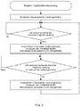
- Fig. 2 shows the sequence of a controller according to the invention for a power take-off 20.
- This includes a vehicle control that controls an automated driving gear, the vehicle drive and the PTO gear 20.
- the PTO is located in a reduced power mode, if possible.
- the vehicle control determines a corresponding power level of the drive.
- the load of the drive can be variable and is determined by other external factors, such as slope or tensile load, applied electrical or hydraulic loads.
- the vehicle control thereby also detects the current state of the drive transmission and determines a current operating point of the vehicle. From this, the currently maximum possible power for the drive is determined. The currently applied drive power in the reduced power mode is compared with the determined value of the maximum possible drive power. In the event that the applied power does not exceed the value determined, there is no intervention by the vehicle control.
- the vehicle control switches over the power take-off control from the power-reduced mode to a normal operating mode, which provides a higher power to the power take-off shaft.
- This switching is done by controlled switching operations in the PTO transmission 20, wherein by the PTO transmission 20 according to the present invention, a switchover can take place under load.
- the vehicle control system increases the speed of the vehicle drive in order to ensure a corresponding increase in power and to adapt the drive gear to a corresponding gear change.
- the vehicle control system reacts autonomously to an increased power requirement of the drive without the operator having to carry out a manual adjustment of the PTO control, the throttle lever for the vehicle drive and the driving gear.
- the vehicle control determines whether the maximum possible power in the reduced power mode is undershot by the currently applied power of the drive. If the condition is met, the PTO control in the switched power reduced mode and the process described runs in reverse order.
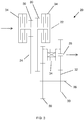
- FIG. 3 an inventive PTO transmission 20 is shown.
- the power take-off 20 has an input shaft 22, a first output shaft 24, a second output shaft 28 and an intermediate shaft 26.
- two gears 32 are provided, which are in each case via a switching element 34 with the input shaft 22 in connection.
- the gears 32 can be rotatably connected to the input shaft 22.
- the gears 32 are in engagement with two associated gears 32 on the first output shaft 24. With these, they each form a pair of gears 30 with the corresponding position of the switching element 34 torque and speed from the input shaft 22 to the first output shaft 24 can be transmitted.
- the first output shaft 24 has three gears 32, two of which together with the gears 32 of the input shaft 22 form two pairs of gears.
- the third gear 32 of the first output shaft 24 is engaged with a gear 32 of the intermediate shaft 26 and forms a third gear pair 30.
- On the second output shaft 28, a further gear 32 is provided, which is in engagement with a second gear 32 of the intermediate shaft 26.
- the intermediate shaft 26 there are two further gears 32, each with the third gear 32 of the first output shaft 24 or the gear 32 of the second output shaft 28 form a third and fourth gear pair 30 by switching the switching element 34.
- the power path to the PTO is switched so that it is passed from the first input shaft 22 via the first output shaft 24 either directly via the second output shaft 28 or via the intermediate shaft 26 and the second output shaft 28.
- one or more switching elements 34 as a power shiftable switching element, an automated switching can be controlled if necessary, controlled by the vehicle control.
- the PTO 20 has an input shaft 22, a first output shaft 24, a second output shaft 28, and an intermediate shaft 26.
- two gears 32 are provided, which are each formed switchable with a switching element 34.
- the two gears 32 each complementary to a gear 32 of the first output shaft 24 form a pair of gears 30.
- a further gear 32 is provided which forms a pair of gears 30 with a gear 32 of the intermediate shaft 26.
- a switching element 34 Between a pair of gears 30, which is provided between the input shaft 22 and the first output shaft and between the gear pair 30, which is formed between the first output shaft 24 and the intermediate shaft 26, there is a switching element 34.
- the switching element 34 can either one or the other gear pair 30 are connected to the second output shaft 28.
- either the power path can be routed via one of the two gears 32 of the input shaft 22 to the first output shaft 24 directly into the second output shaft 28 and the PTO, or with appropriate switching of the switching element via the intermediate shaft 26 and the second output shaft 28 to the PTO.
- four different translations or four different performance levels can be achieved.
- a PTO according to FIG. 5 has, in contrast to the previous embodiments, two input shafts. These are divided into a first input shaft 22 and a second input shaft 36. Between the first and the second input shaft, a switching element 34 is provided.
- the switching element 34 serves to completely shut off the PTO when needed.
- the second input shaft 36 has two gears 32, both of which are operated by a switching element 34.
- the two gears 32 of the second input shaft 36 with two gears 32 on the first output shaft 24 each have a pair of gears 30.
- a further gear 32 on the intermediate shaft 26 is in turn with a gear 32 on the second output shaft 28 in engagement and forms a fourth gear pair 30.
- a switching element 34 Between the gear pair 30 of the first output shaft 24 and the intermediate shaft 26 and the gear pair 30 of the intermediate shaft 26 and the second Output shaft 28 is also a switching element 34, so that either the power path from the first output shaft 24 via the gear pair 30 to the intermediate shaft 26 and the other gear pair 30 to the second output shaft 28 can be passed, or from the first output shaft 24 directly into the second Output shaft 28 to the PTO. This can also provide four gears or power levels for the PTO.
- a further embodiment according to FIG. 6 differs from the design according to FIG. 5 in that a switching element 34 is removed from the second input shaft 36 and instead is now provided on the first output shaft 24 to between two gear pairs 30 between the second input shaft 36 and the first To turn output shaft 24.
- the further structure corresponds to the structure of the embodiment according to FIG. 5 so that also four different gears or power levels can be provided for the PTO.
- an automated switchover in PTO mode can be performed without the operator having to perform manual switching operations.
- the operator is relieved in their work and the proposed method leads to a constant utilization of the vehicle and the vehicle drive while fuel economy.
- All switching elements 34 can be designed both as a load-free switchable switching element or as a power switchable switching element. When switching elements are switchable under load, there is the further advantage that can be switched without a traction interruption between two different modes for PTO operation.
- the advantage of using a load-free switchable switching element is the smaller space that must be used for this purpose.
Abstract
Die Erfindung betrifft ein Zapfwellengetriebe (20) und ein Verfahren, das eine Zapfwellensteuerung, eine Eingangswelle (22), eine erste Ausgangswelle (24), eine parallel angeordnete Zwischenwelle (26), und eine zweite Ausgangswelle (28) aufweist, die koaxial zur ersten Ausgangswelle (24) angeordnet ist.The invention relates to a PTO transmission (20) and a method comprising a PTO control, an input shaft (22), a first output shaft (24), a parallel intermediate shaft (26), and a second output shaft (28) coaxial with the first Output shaft (24) is arranged.
Description
Die vorliegende Erfindung betrifft eine Getriebe für eine Leistungsabgabewelle an landwirtschaftlichen Nutzfahrzeugen und ein Verfahren zur Steuerung desselben.The present invention relates to a transmission for a power output shaft on agricultural vehicles and a method for controlling the same.
Üblicherweise sind Leistungsabgabewellen am vorderen und hinteren Ende von landwirtschaftlichen Fahrzeugen vorgesehen. Mit der Leistungsabgabewelle, auch Zapfwelle genannt, werden angehängte Aggregate mit Leistung versorgt, die bei Feldarbeiten verwendet werden.Typically, power output shafts are provided at the front and rear ends of agricultural vehicles. The output shaft, also referred to as PTO, is used to supply attached units that are used in field work.
Die Aggregate können unterschiedliche Antriebsmomente und -drehzahlen erfordern. Aus diesem Grund sind Zapfwellengetriebe bekannt, die unterschiedliche Drehzahlen bereitstellen. Die bekannten Zapfwellengetriebe ermöglichen ein Umschalten der Betriebsarten der Zapfwelle im lastfreien Zustand.The units may require different drive torques and speeds. For this reason, PTO are known to provide different speeds. The known power take-off gearboxes allow a switchover of the operating modes of the PTO shaft in the load-free state.
Die üblichen Drehzahlen der Zapfwellen sind 540 und 1000 Umdrehungen pro Minute. Es sind neben diesen auch Gänge üblich, welche die gleiche Drehzahl aufweisen, jedoch mit einer geringen Antriebsleistung des landwirtschaftlichen Fahrzeugs betrieben werden können. Dies ermöglicht die Einsparung von Kraftstoff bzw. Antriebsenergie.The usual speeds of the PTO are 540 and 1000 revolutions per minute. In addition to these, it is also common to use gears which have the same rotational speed but can be operated with a low driving power of the agricultural vehicle. This allows the saving of fuel or drive energy.
Die vorliegende Erfindung weist nach Anspruch 1 ein Zapfwellengetriebe auf, mit einer Zapfwellensteuerung, einer Eingangswelle, einer ersten Ausgangswelle, einer parallel angeordneten Zwischenwelle, einer zweiten Ausgangswelle, die koaxial zur ersten Ausgangswelle angeordnet ist, vier Zahnradpaaren, die derart angeordnet sind, dass die Eingangswelle zwei Zahnräder, die erste Ausgangswelle drei Zahnräder, die Zwischenwelle zwei Zahnräder und die zweite Ausgangswelle ein Zahnrad aufweist, so dass zwei Zahnradpaare zwischen der Eingangswelle und der ersten Ausgangswelle, ein Zahnradpaar zwischen der ersten Ausgangswelle und der Zwischenwelle und ein Zahnradpaar zwischen der Zwischenwelle und der zweiten Ausgangswelle im Eingriff sind, wobei wenigstens ein Zahnrad je Zahnradpaar schaltbar ist.The present invention according to claim 1, a power take-off, with a PTO control, an input shaft, a first output shaft, a parallel intermediate shaft, a second output shaft, which is arranged coaxially to the first output shaft, four gear pairs, which are arranged such that the input shaft two gears, the first output shaft three gears, the intermediate shaft two gears and the second output shaft has a gear, so that two pairs of gears between the input shaft and the first output shaft, a pair of gears between the first output shaft and the intermediate shaft and a pair of gears between the intermediate shaft and the second output shaft are engaged, wherein at least one gear per gear pair is switchable.
Das Zapfwellengetriebe stellt vier Gänge bereit, die unterschiedliche Drehzahlen und/oder unterschiedliche Leistungen für die Zapfwelle im Betrieb ermöglichen. Es wird ein kompaktes Zapfwellengetriebe zur Verfügung gestellt. Mit der Schaltbarkeit der Zahnräder kann eine angepasste Schaltstrategie realisiert werden, wobei durch die schaltbaren Zahnräder die Zahnräder wahlweise einen Freilauf aufweisen, oder mit der jeweiligen Welle verbunden sind. In neutraler Stellung laufen die Zahnräder somit frei und übertragen keine Leistung.The PTO provides four gears that allow different speeds and / or different powers for the PTO in operation. A compact PTO gearbox will be provided. With the switchability of the gears, an adapted shift strategy can be realized, wherein the gears optionally have a freewheel through the shiftable gears, or are connected to the respective shaft. In neutral position, the gears thus run free and transfer no power.
Zwischen den Wellen kann durch die schaltbaren Zahnräder eine Verbindung hergestellt werden.Between the waves can be made by the switchable gears a connection.
Zur Schaltung der Zahnräder kommen unter anderem Lamellenkupplungen oder Klauenkupplungen in Frage. Lamellenkupplungen erlauben den Schaltvorgang unter anliegender Last, so dass Stöße in Leistungspfad vermieden werden. Klauenkupplungen erfordern das Entlasten des Leistungspfads zum Schalten, ermöglichen jedoch eine Konstruktion bei kleinerem Bauraum als eine Lamellenkupplung.Among other things, multi-disc clutches or jaw clutches come into consideration for switching the gears. Multi-disc clutches allow the shifting process under applied load, so that impacts in the power path are avoided. Jaw clutches require relieving the power path for shifting, but allow for a design with less space than a multi-plate clutch.
Nach einer weiteren Ausführung kann die Eingangswelle wenigstens ein Schaltelement aufweisen, und die erste Ausgangswelle höchstens zwei Schaltelemente aufweisen, mit denen die Zahnräder schaltbar sind.According to a further embodiment, the input shaft may comprise at least one switching element, and the first output shaft having at most two switching elements, with which the gears are switchable.
Die Anordnung der Schaltelemente ermöglicht es, die Zahnräder drehfest mit ihrer jeweiligen Welle zu verbinden oder diese im Freilauf zu betreiben. Bei einer Anordnung, die zwei Zahnräder mit einem Schaltelement bedient, kann eine kompakte Bauweise realisiert werden. Es ist möglich, beide Zahnradpaare auf der Eingangswelle durch ein Schaltelement zu schalten, wie auch auf der ersten Ausgangswelle. Die Zwischenwelle kann dabei kein Schaltelement aufweisen und kann mit einem geringeren Bauraum realisiert werden.The arrangement of the switching elements makes it possible to connect the gears rotatably with their respective shaft or to operate them in the freewheel. In an arrangement that operates two gears with a switching element, a compact design can be realized. It is possible to switch both gear pairs on the input shaft through a switching element, as well as on the first output shaft. The intermediate shaft can have no switching element and can be realized with a smaller space.
In einer weiteren Ausbildung kann durch das wenigstens eine Schaltelement auf der Eingangswelle die Eingangswelle mit der ersten Ausgangswelle verbindbar sein, und durch die höchstens zwei Schaltelemente der ersten Ausgangswelle die erste Ausgangswelle mit der Eingangswelle und mit der zweiten Ausgangswelle verbindbar sein, oder die Eingangswelle mit der ersten Ausgangswelle, der Zwischenwelle und der zweiten Ausgangswelle verbindbar sein.In a further embodiment, by the at least one switching element on the input shaft, the input shaft with the first output shaft be connectable, and be connected by the at most two switching elements of the first output shaft, the first output shaft with the input shaft and the second output shaft, or the input shaft with the first output shaft, the intermediate shaft and the second output shaft be connectable.
Die Versorgung der Zapfwelle mit Antriebsenergie findet über die zweite Ausgangswelle statt. Mit Hilfe der Schaltelemente kann zwischen den zwei Zahnradpaaren der Eingangswelle geschaltet werden und zwischen dem Leistungspfad, der direkt von der ersten zur zweiten Ausgangswelle führt, oder von der ersten Ausgangswelle über die Zwischenwelle zur zweiten Ausgangswelle. Mit dieser Strategie können vier unterschiedliche Leistungspfade bereitgestellt werden.The supply of the PTO shaft with drive energy takes place via the second output shaft. By means of the switching elements can be switched between the two gear pairs of the input shaft and between the power path that leads directly from the first to the second output shaft, or from the first output shaft via the intermediate shaft to the second output shaft. With this strategy, four different performance paths can be provided.
Eine weitere Ausführung betrifft ein Zapfwellengetriebe mit einer Zapfwellensteuerung, einer ersten Eingangswelle, einer zweiten Eingangswelle, einer ersten Ausgangswelle, einer parallel angeordneten Zwischenwelle, einer zweiten Ausgangswelle, die koaxial zur ersten Ausgangswelle angeordnet ist, vier Zahnradpaaren, die derart angeordnet sind, dass die zweite Eingangswelle zwei Zahnräder, die erste Ausgangswelle drei Zahnräder, die Zwischenwelle zwei Zahnräder und die zweite Ausgangswelle ein Zahnrad aufweist, so dass zwei Zahnradpaare zwischen der zweiten Eingangswelle und der ersten Ausgangswelle, ein Zahnradpaar zwischen der ersten Ausgangswelle und der Zwischenwelle und ein Zahnradpaar zwischen der Zwischenwelle und der zweiten Ausgangswelle im Eingriff sind, wobei wenigstens ein Zahnrad je Zahnradpaar schaltbar ist.Another embodiment relates to a PTO with a PTO control, a first input shaft, a second input shaft, a first output shaft, a parallel intermediate shaft, a second output shaft, which is arranged coaxially to the first output shaft, four gear pairs, which are arranged such that the second Input shaft two gears, the first output shaft three gears, the intermediate shaft two gears and the second output shaft has a gear, so that two pairs of gears between the second input shaft and the first output shaft, a Gear pair between the first output shaft and the intermediate shaft and a pair of gears between the intermediate shaft and the second output shaft are engaged, wherein at least one gear per gear pair is switchable.
Die Ausführung ermöglicht es, vier Gänge bereitzustellen, die unterschiedliche Drehzahlen und/oder unterschiedliche Leistungen für die Zapfwelle erlauben. Es wird ein kompaktes Zapfwellengetriebe zur Verfügung gestellt. Mit der Schaltbarkeit der Zahnräder kann eine angepasste Schaltstrategie realisiert werden, wobei durch die schaltbaren Zahnräder die Zahnräder wahlweise einen Freilauf aufweisen, oder mit der jeweiligen Welle verbunden sind. In neutraler Stellung laufen die Zahnräder somit frei und übertragen keine Leistung. Zwischen den Wellen kann durch die schaltbaren Zahnräder eine Verbindung hergestellt werden. Die erste Eingangswelle kann von der zweiten Eingangswelle entkoppelt werden, so dass eine Abschaltung der Zapfwelle ermöglicht ist.The design makes it possible to provide four gears that allow different speeds and / or different powers for the PTO shaft. A compact PTO gearbox will be provided. With the switchability of the gears, an adapted shift strategy can be realized, wherein the gears optionally have a freewheel through the shiftable gears, or are connected to the respective shaft. In neutral position, the gears thus run free and transfer no power. Between the waves can be made by the switchable gears a connection. The first input shaft can be decoupled from the second input shaft, so that a shutdown of the PTO is possible.
In einer Ausbildung kann die zweite Eingangswelle wenigstens ein Schaltelement aufweisen, und die erste Ausgangswelle höchstens zwei Schaltelemente, mit denen die Zahnräder schaltbar sind.In one embodiment, the second input shaft may comprise at least one switching element, and the first output shaft at most two switching elements, with which the gears are switchable.
Die Anordnung der Schaltelemente ermöglicht es, die Zahnräder drehfest mit ihrer jeweiligen Welle zu verbinden oder diese im Freilauf zu betreiben. Bei einer Anordnung, die zwei Zahnräder mit einem Schaltelement bedient, kann eine kompakte Bauweise realisiert werden. Es ist möglich, beide Zahnradpaare auf der zweiten Eingangswelle durch ein Schaltelement zu schalten, wie auch auf der ersten Ausgangswelle. Die Zwischenwelle kann dabei kein Schaltelement aufweisen und kann mit einem geringeren Bauraum realisiert werden.The arrangement of the switching elements makes it possible to connect the gears rotatably with their respective shaft or to operate them in the freewheel. In an arrangement that operates two gears with a switching element, a compact design can be realized. It is possible to switch both gear pairs on the second input shaft through a switching element, as well as on the first output shaft. The intermediate shaft can have no switching element and can be realized with a smaller space.
Bei einer Ausführung kann durch das wenigstens eine Schaltelement auf der zweiten Eingangswelle die zweite Eingangswelle mit der ersten Ausgangswelle verbindbar sein, und durch die höchstens zwei Schaltelemente der ersten Ausgangswelle die erste Ausgangswelle mit der zweiten Eingangswelle und mit der zweiten Ausgangswelle verbindbar sein, oder die zweite Eingangswelle mit der ersten Ausgangswelle, der Zwischenwelle und der zweiten Ausgangswelle verbindbar sein.In one embodiment, the second input shaft may be connectable to the first output shaft by the at least one switching element on the second input shaft, and the first output shaft may be connectable to the second input shaft and the second output shaft through the at most two switching elements of the first output shaft, or the second Input shaft with the first output shaft, the intermediate shaft and the second output shaft be connectable.
Die Versorgung der Zapfwelle findet über die zweite Ausgangswelle statt. Mit Hilfe der Schaltelemente kann zwischen den zwei Zahnradpaaren der zweiten Eingangswelle geschaltet werden und zwischen dem Leistungspfad, der direkt von der ersten zur zweiten Ausgangswelle führt, oder von der ersten Ausgangswelle über die Zwischenwelle zur zweiten Ausgangswelle. Mit dieser Strategie können vier unterschiedliche Leistungspfade bereitgestellt werden.The supply of the PTO takes place via the second output shaft. By means of the switching elements can be switched between the two gear pairs of the second input shaft and between the power path that leads directly from the first to the second output shaft, or from the first output shaft via the intermediate shaft to the second output shaft. With this strategy, four different performance paths can be provided.
In einer weiteren Ausbildung können die Schaltelemente unter Last schaltbar oder lastfrei schaltbar ausgeführt sein.In a further embodiment, the switching elements can be designed switchable or load-free switchable under load.
Mit Hilfe von Schaltelementen, die unter Last schaltbar sind, etwa eine Lamellenkupplung, kann während dem Betrieb der Zapfwelle ohne Entlastung des Antriebsstrangs eine Anpassung des Zapfwellengetriebes und generell des Betriebs der Zapfwelle vorgenommen werden. Dies führt zu einer höheren Qualität bei der Bedienbarkeit der Zapfwelle und bei der Anpassung der Fahrzeugparameter. Fahrzeugparameter können die Antriebsdrehzahl des landwirtschaftlichen Fahrzeugs sein, oder auch die Gangauswahl eines zusätzlich bei landwirtschaftlichen Fahrzeugen üblicherweise vorgesehenen automatisierten Fahrgetriebes.By means of switching elements which can be switched under load, such as a multi-plate clutch, can be made during operation of the PTO without relieving the power train, an adaptation of the PTO and generally the operation of the PTO. This leads to a higher quality in the operability of the PTO and in the adjustment of the vehicle parameters. Vehicle parameters may be the drive speed of the agricultural vehicle, or the gear selection of an additionally provided in agricultural vehicles usually automated transmission.
Bei einer weiteren Ausführung kann wenigstens eines der Schaltelemente auf der zweiten Ausgangswelle eine Neutralstellung aufweisen.In a further embodiment, at least one of the switching elements may have a neutral position on the second output shaft.
Die Neutralstellung des Schaltelements ermöglicht ein Abschalten des Betriebs der Zapfwelle. In der Neutralstellung wird das zugehörige Zahnrad nicht mit der Welle verbunden und befindet sich im Freilauf. Dies kann dazu verwendet werden, das Zahnrad aktiv zu bremsen, etwa durch ein Bremsmittel. Die Bremsung kann notwendig sein, da durch das Schaltelement, etwa eine Lamellenkupplung, ein Schleppmoment durch Reibung des verwendeten Hydrauliköls erzeugt werden kann, welches auch in Neutralstellung des Schaltelementes zur Drehung der Zapfwelle führen kann.The neutral position of the switching element allows a shutdown of the operation of the PTO. In the neutral position, the associated gear is not connected to the shaft and is in free-running. This can be used to actively brake the gear, such as by a braking means. The braking may be necessary, since by the switching element, such as a multi-plate clutch, a drag torque can be generated by friction of the hydraulic oil used, which can also lead to the rotation of the PTO in the neutral position of the switching element.
Eine weitere Ausbildung der Erfindung betrifft ein Verfahren zum Schalten eines Zapfwellengetriebes, das ein Zapfwellengetriebe nach einem der vorangehenden Ansprüche, eine Fahrzeugsteuerung zur Steuerung eines automatisierten Fahrgetriebes, eines Fahrzeugantriebs und eines Zapfwellengetriebes aufweist, wobei der Fahrzeugsteuerung eine momentane Antriebsleistung vorliegt, die mit einer zu einem Zapfwellengetriebegang zum Betrieb mit reduzierter Antriebsdrehzahl gehörenden maximalen Antriebsleistung verglichen wird, und bei einem Überschreiten der maximalen Antriebsleistung einen Gangwechsel des Zapfwellengetriebes und eine Übersetzungsanpassung des Fahrgetriebes dahingehend vornimmt, dass die Antriebsdrehzahl zu einem Betriebspunkt höherer Leistungsverfügbarkeit verstellt wird.A further embodiment of the invention relates to a method for switching a power take-off, comprising a PTO transmission according to one of the preceding claims, a vehicle control for controlling an automated transmission, a vehicle drive and a PTO, wherein the vehicle control is a current driving power, with a to a PTO gear to operate at reduced drive speed associated maximum drive power is compared, and performs a gear change of the PTO and a translation adjustment of the transmission to the effect that the drive speed is adjusted to an operating point of higher power availability when exceeding the maximum drive power.
Das Fahrzeug und das Zapfwellengetriebe werden durch die Fahrzeugsteuerung, wenn möglich, im reduzierten Leistungsmodus betrieben. Im Bedarfsfall erfolgt die Umschaltung in einen sogenannten normalen Modus, welcher die volle Leistungserbringung ermöglicht, jedoch auch einen höheren Energiebedarf für den Fahrantrieb mit sich bringt.The vehicle and the PTO are operated by the vehicle control, if possible, in the reduced power mode. If necessary, the switchover takes place in a so-called normal mode, which allows the full performance, but also brings a higher energy demand for the drive with it.
Im Bedarfsfall wird durch die Fahrzeugsteuerung die Leistung für die Zapfwelle auf ein höheres Niveau angehoben und erlaubt den adaptiven Betrieb der Zapfwelle an wechselnde Fahrzeuganforderungen.If necessary, the power steering system raises PTO power to a higher level and allows the PTO to adaptively adapt to changing vehicle requirements.
Das Verfahren ermöglicht eine automatisierte und ohne Zugkraftunterbrechung der Zapfwelle ablaufende Schaltung des Leistungspfades des Zapfwellengetriebes.The method allows an automated and running without interrupting the power take-off PTO circuit of the power path of the power take-off.
Bei einer weiteren Ausführung kann der Fahrzeugsteuerung eine momentane Antriebsleistung vorliegen, die mit einer zu einem Zapfwellengetriebegang zum Betrieb mit reduzierter Antriebsdrehzahl gehörenden maximalen Antriebsleistung verglichen wird, und bei einem Unterschreiten der maximalen Antriebsleistung einen Gangwechsel des Zapfwellengetriebes und eine Übersetzungsanpassung des Fahrgetriebes dahingehend vornimmt, dass die Antriebsdrehzahl zu einem Betriebspunkt niedriger Leistungsverfügbarkeit verstellt wird.In a further embodiment, the vehicle control can present a momentary drive power, which is compared with a maximum drive power associated with a PTO gear for operation at reduced drive speed, and performs a gear change of the PTO and a translation adjustment of the transmission to below the maximum drive power, that the Drive speed is adjusted to an operating point low power availability.
Das Verfahren senkt die zur Verfügung stehende Leistung für die Zapfwelle damit automatisiert wieder auf das reduzierte Leistungsniveau herab, wenn die Leistungsanforderungen an die Zapfwelle sinken. Es wird die Einsparung von Antriebsenergie sichergestellt, gleichzeitig kann der Verschleiß reduziert werden und eine zu hohe Antriebslast auf das Zapfwellengetriebe wird vermieden.The process automatically lowers the power available to the PTO shaft to the reduced power level as power demands on the PTO drop. It ensures the saving of drive energy, at the same time the wear can be reduced and an excessive drive load on the PTO gearbox is avoided.
In einer weiteren Ausbildung kann die Fahrzeugsteuerung die Betriebskonfiguration bestehend aus Fahrgetriebeübersetzung, Zapfwellengetriebegang und Antriebsdrehzahl bestehen lassen, wenn die neu ermittelte Betriebskonfiguration der aktuellen entspricht.In a further embodiment, the vehicle controller may pass the operating configuration consisting of driving gear ratio, PTO gear and drive speed, if the newly determined operating configuration of the current equivalent.
Das Verfahren prüft, ob sich die Anforderungen an das Zapfwellengetriebe ändern, stellt gemäß den vorangehenden Ausführungen die Steuerung um, oder bewertet, dass eine Änderung in einen anderen Leistungsmodus nicht notwendig ist. Unnötige Schaltvorgänge des Fahrzeuggetriebes und Beschleunigungsvorgänge des Antriebs werden vermieden, wodurch auch der Verschleiß des Fahrzeugs reduziert werden kann.The method checks whether the requirements for the power take-off gear change, according to the foregoing, the control over, or judges that a change to another power mode is not necessary. Unnecessary switching operations of the vehicle transmission and acceleration operations of the drive are avoided, whereby the wear of the vehicle can be reduced.
Weitere Ausführungen werden anhand der
- Figur 1:
- die Anwendung eines Zapfwellengetriebes in einem landwirtschaftlichen Fahrzeug;
- Figur 2:
- den Ablauf eines Verfahrens für ein Zapfwellengetriebe
- Figur 3:
- eine Ausführung eines erfindungsgemäßen Zapfwellengetriebes;
- Figur 4:
- eine weitere Ausführung eines erfindungsgemäßen Zapfwellengetriebes;
- Figur 5:
- eine weitere Ausführung eines erfindungsgemäßen Zapfwellengetriebes;
- Figur 6:
- eine weitere Ausführung eines erfindungsgemäßen Zapfwellengetriebes.
- FIG. 1:
- the application of a PTO in an agricultural vehicle;
- FIG. 2:
- the sequence of a procedure for a PTO transmission
- FIG. 3:
- an embodiment of a PTO transmission according to the invention;
- FIG. 4:
- a further embodiment of a PTO transmission according to the invention;
- FIG. 5:
- a further embodiment of a PTO transmission according to the invention;
- FIG. 6:
- a further embodiment of a PTO transmission according to the invention.
Die Erfindung kann in einem landwirtschaftlichen Nutzfahrzeug 10 in
Üblich sind Zapfwellendrehzahlen von 540 und 1000 Umdrehungen pro Minute. Es ist weiterhin möglich, die Zapfwelle bei den genannten Drehzahlen in einem reduzierten Leistungsmodus zu betreiben. Die Zapfwelle wird dann mit einer geringeren Antriebsleitung versorgt. Dies führt zur Einsparung von Antriebsenergie.The usual PTO speeds are 540 and 1000 revolutions per minute. It is also possible to operate the PTO at the speeds mentioned in a reduced power mode. The PTO is then supplied with a lower drive line. This leads to the saving of drive energy.
Für einen bestimmten Fahrzustand mit einer gezielt gewählten Drehzahl der Zapfwelle bestimmt die Fahrzeugsteuerung ein entsprechendes Leistungsniveau des Antriebs. Die Belastung des Antriebes kann wechselnd sein und wird durch weitere äußere Faktoren, wie Steigung oder Zuglast, anliegende elektrische oder hydraulische Lasten bestimmt.For a given driving condition with a selectively selected speed of the PTO, the vehicle control determines a corresponding power level of the drive. The load of the drive can be variable and is determined by other external factors, such as slope or tensile load, applied electrical or hydraulic loads.
Die Fahrzeugsteuerung erfasst dabei auch den aktuellen Zustand des Fahrgetriebes und bestimmt einen aktuellen Betriebspunkt des Fahrzeugs. Daraus wird die aktuell maximal mögliche Leistung für den Antrieb ermittelt. Die momentan anliegende Antriebsleistung im reduzierten Leistungsmodus wird mit dem ermittelten Wert der maximal möglichen Antriebsleistung abgeglichen. Für den Fall, dass die anliegende Leistung den ermittelten Wert nicht überschreitet, erfolgt kein Eingriff durch die Fahrzeugsteuerung.The vehicle control thereby also detects the current state of the drive transmission and determines a current operating point of the vehicle. From this, the currently maximum possible power for the drive is determined. The currently applied drive power in the reduced power mode is compared with the determined value of the maximum possible drive power. In the event that the applied power does not exceed the value determined, there is no intervention by the vehicle control.
Bei einem Überschreiten des ermittelten Werts der maximal möglichen Leistung durch die aktuell anliegende Leistung im reduzierten Leistungsmodus erfolgt durch die Fahrzeugsteuerung ein Umschalten der Zapfwellensteuerung vom leistungsreduzierten Modus in einen normalen Betriebsmodus, der eine höhere Leistung an die Zapfwelle bereitstellt. Dieses Umschalten erfolgt durch gesteuerte Schaltvorgänge im Zapfwellengetriebe 20, wobei durch das Zapfwellengetriebe 20 nach der vorliegenden Erfindung ein Umschalten unter Last erfolgen kann.If the determined value of the maximum possible power is exceeded by the currently applied power in the reduced power mode, the vehicle control switches over the power take-off control from the power-reduced mode to a normal operating mode, which provides a higher power to the power take-off shaft. This switching is done by controlled switching operations in the
Gleichzeitig erfolgt durch die Fahrzeugsteuerung eine Anhebung der Drehzahl des Fahrzeugantriebs, um entsprechenden Leistungszuwachs sicherzustellen und ein Anpassen der Fahrgetriebes durch einen entsprechenden Gangwechsel. Damit reagiert die Fahrzeugsteuerung autonom auf ein gestiegenes Leistungserfordernis des Antriebs, ohne dass die Bedienperson einen manuellen Abgleich der Zapfwellensteuerung, des Gashebels für den Fahrzeugantrieb und des Fahrgetriebes vornehmen muss.At the same time, the vehicle control system increases the speed of the vehicle drive in order to ensure a corresponding increase in power and to adapt the drive gear to a corresponding gear change. Thus, the vehicle control system reacts autonomously to an increased power requirement of the drive without the operator having to carry out a manual adjustment of the PTO control, the throttle lever for the vehicle drive and the driving gear.
Sollte sich die Zapfwellensteuerung im normalen Betriebsmodus befinden, wird durch die Fahrzeugsteuerung ermittelt, ob eine maximal mögliche Leistung im reduzierten Leistungsmodus durch die aktuell anliegende Leistung des Antriebs unterschritten wird. Ist die Bedingung erfüllt, wird durch die Fahrzeugsteuerung die Zapfwellensteuerung in den leistungsreduzierten Modus geschaltet und der geschilderte Ablauf läuft in umgekehrter Reihenfolge ab.If the PTO control is in the normal operating mode, the vehicle control determines whether the maximum possible power in the reduced power mode is undershot by the currently applied power of the drive. If the condition is met, the PTO control in the switched power reduced mode and the process described runs in reverse order.
In
Auf der Zwischenwelle 26 befinden sich zwei weitere Zahnräder 32, die jeweils mit dem dritten Zahnrad 32 der ersten Ausgangswelle 24 oder dem Zahnrad 32 der zweiten Ausgangswelle 28 ein drittes und viertes Zahnradpaar 30 bilden durch das Umschalten des Schaltelementes 34. Zwischen der ersten Ausgangswelle 24 und der zweiten Ausgangswelle 28 wird der Leistungspfad zur die Zapfwelle derart umgeschaltet, dass dieser von der ersten Eingangswelle 22 über die erste Ausgangswelle 24 entweder direkt über die zweite Ausgangswelle 28 oder über die Zwischenwelle 26 und die zweite Ausgangswelle 28 geleitet wird. Durch die Ausbildung ein oder mehrerer Schaltelemente 34 als einen lastschaltbares Schaltelement kann ein automatisiertes Umschalten im Bedarfsfall gesteuert durch die Fahrzeugsteuerung ermöglicht werden.On the
Gemäß der Darstellung der
Ein Zapfgetriebe gemäß
Das Schaltelement 34 dient dazu, die Zapfwelle bei Bedarf vollständig abzuschalten. Die zweite Eingangswelle 36 verfügt über zwei Zahnräder 32, die beide durch ein Schaltelement 34 bedient werden. Die beiden Zahnräder 32 der zweiten Eingangswelle 36 bilden mit zwei Zahnrädern 32 auf der ersten Ausgangswelle 24 jeweils ein Zahnradpaar 30. Auf der ersten Ausgangswelle 24 ist ein drittes Zahnrad 32 vorgesehen, welches mit einem Zahnrad 32 auf der Zwischenwelle 26 im Eingriff ist und ein Zahnradpaar 30 bildet.The switching
Ein weiteres Zahnrad 32 auf der Zwischenwelle 26 ist wiederum mit einem Zahnrad 32 auf der zweiten Ausgangswelle 28 im Eingriff und bildet ein viertes Zahnradpaar 30. Zwischen dem Zahnradpaar 30 der ersten Ausgangswelle 24 und der Zwischenwelle 26 und dem Zahnradpaar 30 der Zwischenwelle 26 und der zweiten Ausgangswelle 28 befindet sich ebenfalls ein Schaltelement 34, so dass wahlweise der Leistungspfad von der ersten Ausgangswelle 24 über das Zahnradpaar 30 zur Zwischenwelle 26 und über das weitere Zahnradpaar 30 zur zweiten Ausgangswelle 28 geleitet werden kann, oder von der ersten Ausgangswelle 24 direkt in die zweite Ausgangswelle 28 zur Zapfwelle. Hierdurch können ebenfalls vier Gänge oder Leistungsstufen für die Zapfwelle bereitgestellt werden.A
Ein weiteres Ausführungsbeispiel gemäß
Durch die vorliegende Erfindung kann eine automatisierte Umschaltung im Zapfwellenbetrieb vorgenommen werden, ohne dass die Bedienperson manuelle Umschaltvorgänge durchführen muss. Somit wird die Bedienperson in ihrer Arbeit entlastet und das vorgeschlagene Verfahren führt zu einer konstanten Auslastung des Fahrzeugs und des Fahrzeugantriebes bei gleichzeitiger Kraftstoffersparnis.By means of the present invention, an automated switchover in PTO mode can be performed without the operator having to perform manual switching operations. Thus, the operator is relieved in their work and the proposed method leads to a constant utilization of the vehicle and the vehicle drive while fuel economy.
Sämtliche Schaltelemente 34 können sowohl als lastfrei schaltbares Schaltelement oder als lastschaltbares Schaltelement ausgeführt sein. Bei Schaltelementen die unter Last schaltbar sind, ergibt sich weiterhin der Vorteil, dass ohne eine Zugkraftunterbrechung zwischen zwei verschiedenen Modi für den Zapfwellenbetrieb umgeschaltet werden kann.All switching
Der Vorteil bei einer Verwendung eines lastfrei schaltbaren Schaltelementes ist der kleinere Bauraum, der hierfür verwendet werden muss.The advantage of using a load-free switchable switching element is the smaller space that must be used for this purpose.
Claims (11)
Applications Claiming Priority (1)
| Application Number | Priority Date | Filing Date | Title |
|---|---|---|---|
| DE102016220130.1A DE102016220130A1 (en) | 2016-10-14 | 2016-10-14 | PTO |
Publications (1)
| Publication Number | Publication Date |
|---|---|
| EP3308992A1 true EP3308992A1 (en) | 2018-04-18 |
Family
ID=60083207
Family Applications (1)
| Application Number | Title | Priority Date | Filing Date |
|---|---|---|---|
| EP17196168.3A Withdrawn EP3308992A1 (en) | 2016-10-14 | 2017-10-12 | Pto shaft transmission |
Country Status (3)
| Country | Link |
|---|---|
| US (2) | US10723225B2 (en) |
| EP (1) | EP3308992A1 (en) |
| DE (1) | DE102016220130A1 (en) |
Families Citing this family (3)
| Publication number | Priority date | Publication date | Assignee | Title |
|---|---|---|---|---|
| CN109630566B (en) * | 2019-01-30 | 2024-04-05 | 浙江海天机械有限公司 | Wet clutch unit assembly |
| CN110014835A (en) * | 2019-04-01 | 2019-07-16 | 特百佳动力科技有限公司 | Vehicle multi output power takeoff and its control method |
| DE102021113560A1 (en) | 2021-05-26 | 2022-12-01 | Deere & Company | PTO transmission and agricultural utility vehicle |
Citations (3)
| Publication number | Priority date | Publication date | Assignee | Title |
|---|---|---|---|---|
| DE3901229A1 (en) * | 1989-01-17 | 1990-08-16 | Schlueter Anton Muenchen Gmbh | CONVERTER TRANSMISSION, ESPECIALLY FOR TRACTORS |
| EP2675680A1 (en) * | 2011-02-17 | 2013-12-25 | CNH Italia S.p.A. | Pto transmission system in an agricultural or industrial vehicle and method of operating thereof |
| WO2016202515A1 (en) * | 2015-06-16 | 2016-12-22 | Zf Friedrichshafen Ag | Transmission arrangement, overall transmission and mobile agricultural machine |
Family Cites Families (4)
| Publication number | Priority date | Publication date | Assignee | Title |
|---|---|---|---|---|
| US7931560B2 (en) * | 2005-09-08 | 2011-04-26 | Volvo Lastvagnar Ab | Method and arrangement for adapting shifting strategies in a heavy vehicle including an automated transmission and experiencing a PTO load |
| EP1928685B1 (en) * | 2005-09-08 | 2012-06-13 | Volvo Lastvagnar Ab | A method for adapting an automated transmission of a heavy vehicle in consideration of a speed sensitive pto |
| CN101263025B (en) * | 2005-09-08 | 2012-02-01 | 沃尔沃拉斯特瓦格纳公司 | Method for determining power output unit load of heavy vehicle of with mechanical type auto-transmission |
| DE102011084623A1 (en) | 2011-10-17 | 2013-04-18 | Zf Friedrichshafen Ag | Power takeoff gear box e.g. four-level power takeoff gear box, for tractor, has spur gear stages for switching transmission stages, where each gear stage comprises gear wheels arranged on power-takeoff axles and shaft axle |
-
2016
- 2016-10-14 DE DE102016220130.1A patent/DE102016220130A1/en active Pending
-
2017
- 2017-10-12 EP EP17196168.3A patent/EP3308992A1/en not_active Withdrawn
- 2017-10-12 US US15/782,217 patent/US10723225B2/en active Active
-
2020
- 2020-06-17 US US16/904,147 patent/US11376954B2/en active Active
Patent Citations (3)
| Publication number | Priority date | Publication date | Assignee | Title |
|---|---|---|---|---|
| DE3901229A1 (en) * | 1989-01-17 | 1990-08-16 | Schlueter Anton Muenchen Gmbh | CONVERTER TRANSMISSION, ESPECIALLY FOR TRACTORS |
| EP2675680A1 (en) * | 2011-02-17 | 2013-12-25 | CNH Italia S.p.A. | Pto transmission system in an agricultural or industrial vehicle and method of operating thereof |
| WO2016202515A1 (en) * | 2015-06-16 | 2016-12-22 | Zf Friedrichshafen Ag | Transmission arrangement, overall transmission and mobile agricultural machine |
Also Published As
| Publication number | Publication date |
|---|---|
| US20180105037A1 (en) | 2018-04-19 |
| US11376954B2 (en) | 2022-07-05 |
| DE102016220130A1 (en) | 2018-04-19 |
| US10723225B2 (en) | 2020-07-28 |
| US20200324648A1 (en) | 2020-10-15 |
Similar Documents
| Publication | Publication Date | Title |
|---|---|---|
| DE112014000581B4 (en) | Hybrid vehicle | |
| DE102012216277B4 (en) | Transmission device with a planetary gear device | |
| EP2738030A2 (en) | Tensile force assisted multi-group transmission and method of operating the same | |
| WO2002047931A1 (en) | Methods for operating a motor vehicle driven by an internal combustion engine and by two electric machines | |
| DE102006015661A1 (en) | Powershift transmission for a commercial vehicle | |
| DE112018008137T5 (en) | Hybrid propulsion system and operating method, torque distribution method and gear shift control method therefor | |
| DE112009002276B4 (en) | Power transmission device | |
| DE102010036748A1 (en) | Power transmission device and power transmission system | |
| WO2016202515A1 (en) | Transmission arrangement, overall transmission and mobile agricultural machine | |
| WO2014166541A1 (en) | Gearbox and method for operating the gearbox | |
| DE102008052448B4 (en) | Dual-clutch transmission and method for its control | |
| EP3308992A1 (en) | Pto shaft transmission | |
| WO2016131591A1 (en) | Dual clutch transmission for a motor vehicle | |
| EP0175192A1 (en) | Drive unit for vehicle propulsion consisting of a variable hydrostatic transmission followed by a gearbox | |
| EP2979008A1 (en) | Transmission control circuit | |
| EP2857246B1 (en) | Agricultural work machine | |
| EP1357309A2 (en) | Method for controlling the starting procedure of a dual clutch transmission | |
| DE102006008749A1 (en) | Hybrid drive unit for motorized vehicle has electronic control unit arranged to set second input shaft at suitable revs for relevant gear | |
| DE102011084622A1 (en) | Power-takeoff gear box i.e. three-speed gear box, for tractor, has pin shaft arranged offset of axis of input shafts, two gear stages coupled with one of input shafts and wheels, and third gear stage coupled with other shaft and wheels | |
| DE102015215070B4 (en) | Transmission system for a hybrid drive of a motor vehicle | |
| WO2020177887A1 (en) | Transmission assembly, motor vehicle powertrain, and method for operating same | |
| DE102012216229A1 (en) | Power train installed in drive assembly of e.g. rail vehicle, has main transmission that is switched in response to selection of respective direction of rail vehicle so as to provide no reversal or reversal of rotation respectively | |
| DE102011055177B4 (en) | Hydrostatic drive for an all-wheel drive machine | |
| DE102022200713B4 (en) | Drive train for a work machine | |
| EP4168264B1 (en) | Method for controlling a hybrid drive system for a motor vehicle |
Legal Events
| Date | Code | Title | Description |
|---|---|---|---|
| PUAI | Public reference made under article 153(3) epc to a published international application that has entered the european phase |
Free format text: ORIGINAL CODE: 0009012 |
|
| STAA | Information on the status of an ep patent application or granted ep patent |
Free format text: STATUS: THE APPLICATION HAS BEEN PUBLISHED |
|
| AK | Designated contracting states |
Kind code of ref document: A1 Designated state(s): AL AT BE BG CH CY CZ DE DK EE ES FI FR GB GR HR HU IE IS IT LI LT LU LV MC MK MT NL NO PL PT RO RS SE SI SK SM TR |
|
| AX | Request for extension of the european patent |
Extension state: BA ME |
|
| STAA | Information on the status of an ep patent application or granted ep patent |
Free format text: STATUS: REQUEST FOR EXAMINATION WAS MADE |
|
| 17P | Request for examination filed |
Effective date: 20181018 |
|
| RBV | Designated contracting states (corrected) |
Designated state(s): AL AT BE BG CH CY CZ DE DK EE ES FI FR GB GR HR HU IE IS IT LI LT LU LV MC MK MT NL NO PL PT RO RS SE SI SK SM TR |
|
| STAA | Information on the status of an ep patent application or granted ep patent |
Free format text: STATUS: THE APPLICATION IS DEEMED TO BE WITHDRAWN |
|
| 18D | Application deemed to be withdrawn |
Effective date: 20181019 |