EP0174889B1 - Schmierungsanlage für eine Getriebeeinheit für Kraftwagen mit zwei Antriebswellen - Google Patents
Schmierungsanlage für eine Getriebeeinheit für Kraftwagen mit zwei Antriebswellen Download PDFInfo
- Publication number
- EP0174889B1 EP0174889B1 EP85401613A EP85401613A EP0174889B1 EP 0174889 B1 EP0174889 B1 EP 0174889B1 EP 85401613 A EP85401613 A EP 85401613A EP 85401613 A EP85401613 A EP 85401613A EP 0174889 B1 EP0174889 B1 EP 0174889B1
- Authority
- EP
- European Patent Office
- Prior art keywords
- pump
- face
- housing
- orifices
- input shaft
- Prior art date
- Legal status (The legal status is an assumption and is not a legal conclusion. Google has not performed a legal analysis and makes no representation as to the accuracy of the status listed.)
- Expired
Links
- 230000005540 biological transmission Effects 0.000 title claims description 8
- 230000001050 lubricating effect Effects 0.000 title claims 2
- 239000007788 liquid Substances 0.000 description 13
- 238000005461 lubrication Methods 0.000 description 8
- 125000006850 spacer group Chemical group 0.000 description 6
- 239000000314 lubricant Substances 0.000 description 4
- CXURGFRDGROIKG-UHFFFAOYSA-N 3,3-bis(chloromethyl)oxetane Chemical compound ClCC1(CCl)COC1 CXURGFRDGROIKG-UHFFFAOYSA-N 0.000 description 1
- 230000005587 bubbling Effects 0.000 description 1
- 239000003638 chemical reducing agent Substances 0.000 description 1
- 230000000694 effects Effects 0.000 description 1
- 238000004513 sizing Methods 0.000 description 1
- 238000011144 upstream manufacturing Methods 0.000 description 1
Images
Classifications
-
- F—MECHANICAL ENGINEERING; LIGHTING; HEATING; WEAPONS; BLASTING
- F16—ENGINEERING ELEMENTS AND UNITS; GENERAL MEASURES FOR PRODUCING AND MAINTAINING EFFECTIVE FUNCTIONING OF MACHINES OR INSTALLATIONS; THERMAL INSULATION IN GENERAL
- F16N—LUBRICATING
- F16N7/00—Arrangements for supplying oil or unspecified lubricant from a stationary reservoir or the equivalent in or on the machine or member to be lubricated
- F16N7/36—Arrangements for supplying oil or unspecified lubricant from a stationary reservoir or the equivalent in or on the machine or member to be lubricated with feed by pumping action of the member to be lubricated or of a shaft of the machine; Centrifugal lubrication
-
- F—MECHANICAL ENGINEERING; LIGHTING; HEATING; WEAPONS; BLASTING
- F16—ENGINEERING ELEMENTS AND UNITS; GENERAL MEASURES FOR PRODUCING AND MAINTAINING EFFECTIVE FUNCTIONING OF MACHINES OR INSTALLATIONS; THERMAL INSULATION IN GENERAL
- F16H—GEARING
- F16H57/00—General details of gearing
- F16H57/04—Features relating to lubrication or cooling or heating
- F16H57/0434—Features relating to lubrication or cooling or heating relating to lubrication supply, e.g. pumps; Pressure control
Definitions
- the present invention relates to the lubrication of the transmission groups which equip certain motor vehicles and which connect to several drive shafts of the vehicle wheels a shaft capable of turning in one or the other direction, this shaft being generally powertrain output shaft comprising a gearbox in which a reverse gear can be established.
- the driven wheels are in particular those of two driving axles of the vehicle and the transmission group comprises various gear trains, in particular epicyclic, having a differential, reducing or torque distributing effect.
- the object of the invention is to provide a
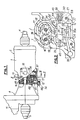
- a transmission group 2 connecting two shafts 3, 4 and a shaft 5, an input shaft 6 coupled to an output shaft 7 of a powertrain 8.
- the shafts 3, 4 can for example drive the front wheels, and the shaft 5 the rear wheels of a motor vehicle.
- Group 8 has a conventional gearbox fitted with several forward and reverse gear ratios, so that shafts 6 and 7 are capable of turning in either direction, depending on whether a forward or reverse gear is engaged.
- the shaft 6 crosses perpendicularly a face 9 of the casing 1
- the shaft 7 crosses perpendicularly a face 10 of a casing 11 containing the group 8. Between these faces 9 and 10 is clamped a spacer 12 with opposite parallel faces 13 and 14.
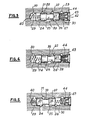
- the conduits 20 and 23 communicate respectively with two opposite chambers 29, 30 delimited in the bore 27 on either side of the drawer.
- the conduits 21, 22 and 24, 25 open at intermediate locations of the bore 27.
- the conduit 25 opens into this same bore, between the two conduits 21, 22 closest to the middle part of the bore.
- the bore 27 is closed by a plug 38, and the drawer 28 comprises, in line with the conduit 25, a central portion of smaller diameter 39 capable of communicating with the conduits 21, 22, 25 as will be indicated below. Note, however, that the duct 25 has a width sufficient to always open out opposite the portion 39, regardless of the position of the drawer.
- a helical spring 40, 41 coaxial with the drawer and of great flexibility is kept compressed, these springs bearing one on the bottom of the bore 27, the other on a central boss 42 of the cap 38.
- One face of the housing 44 is in abutment on the plug 38, and the opposite face is notably spaced from the drawer when the latter is in its median position in FIG. 2.
- the face of the spacer 12 applied, against the face 9 of the casing 1 covers the cavity 15 as well as the conduits 20 to 26 and the channels 31 to 35, so that these channels behave like conduits and the gear pump 16, 17 discharges liquid through the orifice 19 towards the channel 33 or through the orifice 18 towards the channels 34 and 35 depending on whether the toothed wheel 17 rotates clockwise in FIG. 2 or the other way around.
- This wheel 17 is driven from the shaft 6: it is integral with a shaft 45 parallel to the shafts 6 and 7 and carried by a bearing 46 constituted by a portion of the spacer 12; on this shaft 45 is pinned a pinion 47 meshing with a toothing 48 of the shaft 6.
- the drawer 28 If the discharge pressure prevailing in the chamber 29 exceeds a maximum determined value, the drawer 28 is pushed, as shown in Figure 4, against the springs 41 and 43, the housing 44 compressing and the portion 39 of the drawer uncovering the conduit 26. Consequently the liquid can flow in a closed circuit, from the downstream orifice 19 to the upstream orifice 18 of the pump, by the channel 33, the conduits 20, 24, the channels 32, 32a, the conduits 26, 22 and the channels, 34, 35.
- the drawer thus automatically switches the inlet and outlet pipes as soon as the direction of rotation of the pump is reversed.
- This switching would be carried out in the same way in the absence of the springs 40, 41, but these have the advantage of recalling the slide in the middle position when the pump stops, the conduits 21 and 22 then being closed. , which ensures a rapid rise in pressure in one of the two chambers as soon as the pump is started, therefore an immediate sliding of the drawer in the appropriate direction as indicated above.
- a prestressed spring similar to that 43 located in the housing 44, could also be provided in the chamber 29 so as to limit the pressure in the chamber 30, therefore the discharge pressure when the vehicle is traveling in reverse.
- this arrangement would be of little use since in reverse the vehicle speed is usually very low and the pump, therefore turning slowly, does not risk generating excessive pressure of the lubricant.
- the arrangement of the pump and the switching valve in line with the face 9 of the casing 1 is relatively compact, of easy mounting and access.
- the cavity containing the wheels 16,17 can be located in the face 13 of the spacer 12 and covered by the face 9 of the casing 1.
- the slide valve 28 can be fitted in the spacer 12, near the face 13 and the cavity 15, as well as conduits or lights such as 20 to 26 connecting the bore of the valve to channels dug in the face 13 or in the face 9.
- the power take-off of the pump on the input shaft 6 of group 2 is particularly advantageous when this group includes a connectable speed reducer, as is the case for certain vehicles with two driving axles capable of moving on bad ground at very low speed, because even in this case of use, the gearbox being connected, the speed of the pump, linked to the input shaft, is sufficient to ensure a satisfactory flow of lubricant, without involving a large pump sizing.
Landscapes
- Engineering & Computer Science (AREA)
- General Engineering & Computer Science (AREA)
- Mechanical Engineering (AREA)
- General Details Of Gearings (AREA)
Claims (6)
Applications Claiming Priority (2)
| Application Number | Priority Date | Filing Date | Title |
|---|---|---|---|
| FR8413212A FR2569466B1 (fr) | 1984-08-24 | 1984-08-24 | Dispositif de lubrification d'un groupe de transmission, notamment pour vehicule a deux essieux moteurs |
| FR8413212 | 1984-08-24 |
Publications (2)
| Publication Number | Publication Date |
|---|---|
| EP0174889A1 EP0174889A1 (de) | 1986-03-19 |
| EP0174889B1 true EP0174889B1 (de) | 1988-04-27 |
Family
ID=9307218
Family Applications (1)
| Application Number | Title | Priority Date | Filing Date |
|---|---|---|---|
| EP85401613A Expired EP0174889B1 (de) | 1984-08-24 | 1985-08-07 | Schmierungsanlage für eine Getriebeeinheit für Kraftwagen mit zwei Antriebswellen |
Country Status (3)
| Country | Link |
|---|---|
| EP (1) | EP0174889B1 (de) |
| DE (1) | DE3562422D1 (de) |
| FR (1) | FR2569466B1 (de) |
Families Citing this family (1)
| Publication number | Priority date | Publication date | Assignee | Title |
|---|---|---|---|---|
| DE4200910C2 (de) * | 1992-01-16 | 1999-06-02 | Zahnradfabrik Friedrichshafen | Automatgetriebe, insbesondere für Kraftfahrzeuge |
Family Cites Families (3)
| Publication number | Priority date | Publication date | Assignee | Title |
|---|---|---|---|---|
| FR2097445A5 (de) * | 1970-07-07 | 1972-03-03 | Peugeot & Renault | |
| FR2233514B1 (de) * | 1973-06-13 | 1976-09-17 | Mercier Bernard | |
| US4097200A (en) * | 1977-01-03 | 1978-06-27 | Sundstrand Corporation | Self-pressurization system for gearboxes and the like |
-
1984
- 1984-08-24 FR FR8413212A patent/FR2569466B1/fr not_active Expired
-
1985
- 1985-08-07 EP EP85401613A patent/EP0174889B1/de not_active Expired
- 1985-08-07 DE DE8585401613T patent/DE3562422D1/de not_active Expired
Non-Patent Citations (1)
| Title |
|---|
| Zahnradgetriebe, J. LOOMANN, 1970, Seiten 212, 262, 263 * |
Also Published As
| Publication number | Publication date |
|---|---|
| EP0174889A1 (de) | 1986-03-19 |
| DE3562422D1 (en) | 1988-06-01 |
| FR2569466B1 (fr) | 1987-06-12 |
| FR2569466A1 (fr) | 1986-02-28 |
Similar Documents
| Publication | Publication Date | Title |
|---|---|---|
| FR2516874A1 (fr) | Systeme de traction a quatre roues motrices pour un vehicule | |
| FR2604232A1 (fr) | Dispositif de transmission a differentiel, notamment pour vehicule automobile. | |
| FR2567474A1 (fr) | Tracteur agricole | |
| FR2509672A1 (fr) | Ensemble boite de vitesse essieu avant combine pour systeme d'entrainement d'un vehicule a quatre roues motrices | |
| EP1208317A1 (de) | Kraftfahrzeugantriebseinheit mit stufenlosem getriebe | |
| FR2624449A1 (fr) | Dispositif de commande de vitesses pour un vehicule utilitaire, notamment pour un tracteur agricole | |
| FR2887921A1 (fr) | Pompe a huile pour moteur a combustion interne | |
| FR2542407A1 (fr) | Vehicule a entrainement hydrostatique pour deux essieux dont l'un peut etre debraye en marche | |
| EP0658705B1 (de) | Untersetzungsgetriebe und Kraftübertragung mit zwei Gangstufen für ein Kraftfahrzeug | |
| EP0243266B1 (de) | Vorderradantrieb für Fahrzeug | |
| EP0264513B1 (de) | Allradantriebsvorrichtung | |
| FR2661964A1 (fr) | Dispositif de transmission a differentiel et accouplement a glissement controle. | |
| EP0174889B1 (de) | Schmierungsanlage für eine Getriebeeinheit für Kraftwagen mit zwei Antriebswellen | |
| FR2733008A1 (fr) | Installation pour transferer du carburant d'un reservoir vers le moteur d'un vehicule automobile, par une pompe a engrenages ou a transfert et une pompe a cellules semi-rotative | |
| FR2887499A1 (fr) | Systeme d'entrainement d'un vehicule automobile | |
| EP0574289B1 (de) | Getriebe für Fahrzeug mit Frontantrieb und querliegendem Motor mit erhöhter Bodenfreiheit | |
| EP0091347B1 (de) | Mehrfache Zahnradpumpe | |
| EP0989303A1 (de) | Schmierpumpe einer Brennkraftmaschine | |
| EP1141581B1 (de) | Getriebe kompakter bauart mit zwei vorgelegewellen | |
| FR2646380A1 (fr) | Dispositif formant groupe moto-propulseur notamment pour vehicule automobile | |
| WO2006123079A2 (fr) | Boite de vitesses avec pompe a huile laterale | |
| FR2700302A1 (fr) | Dispositif de transmission muni d'un doubleur de gamme pour véhicule à quatre roues motrices. | |
| EP1567751A1 (de) | Ankupellungsvorrichtung eines drehelementes mit einer nockenwelle | |
| EP0307269B1 (de) | Differentialgetriebe für Motorfahrzeuge | |
| FR2910581A1 (fr) | Transmission a fonctionnement continu, a derivation de puissance hydrostatique-mecanique |
Legal Events
| Date | Code | Title | Description |
|---|---|---|---|
| PUAI | Public reference made under article 153(3) epc to a published international application that has entered the european phase |
Free format text: ORIGINAL CODE: 0009012 |
|
| 17P | Request for examination filed |
Effective date: 19860120 |
|
| AK | Designated contracting states |
Kind code of ref document: A1 Designated state(s): DE GB IT |
|
| 17Q | First examination report despatched |
Effective date: 19870410 |
|
| GRAA | (expected) grant |
Free format text: ORIGINAL CODE: 0009210 |
|
| AK | Designated contracting states |
Kind code of ref document: B1 Designated state(s): DE GB IT |
|
| ITF | It: translation for a ep patent filed | ||
| REF | Corresponds to: |
Ref document number: 3562422 Country of ref document: DE Date of ref document: 19880601 |
|
| GBT | Gb: translation of ep patent filed (gb section 77(6)(a)/1977) | ||
| PLBE | No opposition filed within time limit |
Free format text: ORIGINAL CODE: 0009261 |
|
| STAA | Information on the status of an ep patent application or granted ep patent |
Free format text: STATUS: NO OPPOSITION FILED WITHIN TIME LIMIT |
|
| 26N | No opposition filed | ||
| PGFP | Annual fee paid to national office [announced via postgrant information from national office to epo] |
Ref country code: DE Payment date: 19930722 Year of fee payment: 9 |
|
| PGFP | Annual fee paid to national office [announced via postgrant information from national office to epo] |
Ref country code: GB Payment date: 19930730 Year of fee payment: 9 |
|
| ITTA | It: last paid annual fee | ||
| PG25 | Lapsed in a contracting state [announced via postgrant information from national office to epo] |
Ref country code: GB Effective date: 19940807 |
|
| GBPC | Gb: european patent ceased through non-payment of renewal fee |
Effective date: 19940807 |
|
| PG25 | Lapsed in a contracting state [announced via postgrant information from national office to epo] |
Ref country code: DE Effective date: 19950503 |