EP0174591B1 - Device for making packages, especially cigarette cartons - Google Patents
Device for making packages, especially cigarette cartons Download PDFInfo
- Publication number
- EP0174591B1 EP0174591B1 EP85111099A EP85111099A EP0174591B1 EP 0174591 B1 EP0174591 B1 EP 0174591B1 EP 85111099 A EP85111099 A EP 85111099A EP 85111099 A EP85111099 A EP 85111099A EP 0174591 B1 EP0174591 B1 EP 0174591B1
- Authority
- EP
- European Patent Office
- Prior art keywords
- turret
- folding
- pushing
- blank
- Prior art date
- Legal status (The legal status is an assumption and is not a legal conclusion. Google has not performed a legal analysis and makes no representation as to the accuracy of the status listed.)
- Expired - Lifetime
Links
Images


Classifications
-
- B—PERFORMING OPERATIONS; TRANSPORTING
- B65—CONVEYING; PACKING; STORING; HANDLING THIN OR FILAMENTARY MATERIAL
- B65B—MACHINES, APPARATUS OR DEVICES FOR, OR METHODS OF, PACKAGING ARTICLES OR MATERIALS; UNPACKING
- B65B11/00—Wrapping, e.g. partially or wholly enclosing, articles or quantities of material, in strips, sheets or blanks, of flexible material
- B65B11/004—Wrapping, e.g. partially or wholly enclosing, articles or quantities of material, in strips, sheets or blanks, of flexible material in blanks, e.g. sheets precut and creased for folding
-
- B—PERFORMING OPERATIONS; TRANSPORTING
- B65—CONVEYING; PACKING; STORING; HANDLING THIN OR FILAMENTARY MATERIAL
- B65B—MACHINES, APPARATUS OR DEVICES FOR, OR METHODS OF, PACKAGING ARTICLES OR MATERIALS; UNPACKING
- B65B11/00—Wrapping, e.g. partially or wholly enclosing, articles or quantities of material, in strips, sheets or blanks, of flexible material
- B65B11/06—Wrapping articles, or quantities of material, by conveying wrapper and contents in common defined paths
- B65B11/28—Wrapping articles, or quantities of material, by conveying wrapper and contents in common defined paths in a curved path, e.g. on rotary tables or turrets
- B65B11/30—Wrapping articles, or quantities of material, by conveying wrapper and contents in common defined paths in a curved path, e.g. on rotary tables or turrets to fold the wrappers in tubular form about contents
-
- B—PERFORMING OPERATIONS; TRANSPORTING
- B65—CONVEYING; PACKING; STORING; HANDLING THIN OR FILAMENTARY MATERIAL
- B65B—MACHINES, APPARATUS OR DEVICES FOR, OR METHODS OF, PACKAGING ARTICLES OR MATERIALS; UNPACKING
- B65B11/00—Wrapping, e.g. partially or wholly enclosing, articles or quantities of material, in strips, sheets or blanks, of flexible material
- B65B11/58—Applying two or more wrappers, e.g. in succession
Definitions
- the invention relates to a device for producing packs by wrapping objects in at least one blank, in particular for producing large packs from pack groups (cigarette sticks each consisting of several cigarette packs), according to the preamble of patent claim 1.
- Cigarette sticks are made, for example from ten packs of cigarettes that are encased in a single blank. This can consist of cardboard, paper or a film. The construction of such large packs can be chosen so that the pack group is encased by several blanks.
- a device for producing (large) packs, in particular cigarette sticks is explained in DE-A-3 123 496.
- the pack group is alternatively wrapped in a paper blank, in a foil blank or in both of the aforementioned blanks.
- the pack group runs through one or two folding revolvers, in the area of which cuts can be made and folds can be made.
- the large pack provided with one or more blanks leaves the device depending on the structure in the area of a first or in the area of the second folding turret.
- a device for packaging cigarettes is known from EP-A-0 030 359.
- the cigarettes are packed into various packaging wraps by a sequence of packaging processes.
- Corresponding weft blanks are folded using a revolver during the transport of cigarette groups.
- a package is ejected from a revolver pocket by means of a rigid transfer and holding web 90. Problems can arise with such an ejection of a package from a revolver pocket, for example due to tilting of the package.
- the US-A-3 380 227 shows a folding turret, the pockets of which run past a fixed cam.
- ejectors mounted in the pockets are raised in the radial direction.
- a push-out actuated in this way allows a pack to be pushed radially outward from the pocket of a folding revolver into the pocket of an adjacent revolver.
- the cam has an instruction running flank on which a plunger of the pusher moves along, so that the pusher continuously moves radially outwards.
- the object in the pocket is continuously ejected, and this while the folding revolver is rotating.
- this can be a hindrance both for the further rotary movement and also disadvantageous for the transfer to the second folding turret.
- the transfer is made possible in the known device in that the second folding revolver has a type of safety catch on its pockets.
- the ejector of the first folding turret is pushed in again at a certain point by another, separate organ.
- the device structure of the known folding turret according to this document is thus relatively complicated and functionally unreliable.
- DE-B-1 238 378 discloses a folding revolver or a device according to the type mentioned at the beginning.
- This known folding turret has a total of four pockets which are open radially on the outside and are each offset by 90 °.
- Two intersecting plungers are provided between opposite pockets. These are moved by inserting a blank into a turret pocket using a blank stamp.
- a pestle which is in alignment with this in the current state of movement, acts on and ejects a pack located in the opposite turret pocket. The movement of the plunger is therefore linked to the insertion in a pocket. This makes it impossible to match the device to production-specific features.
- the known device can therefore only be used to a limited extent and can be handled very inflexibly.
- the task to be solved now is to remove the elongated objects, e.g. Large packs of the type mentioned, problem-free, i.e. without tilting and resulting damage to remove from the pockets of the folding turret.
- the elongated objects are grasped and pushed out in their full length in the turret pockets by means of the pushers, which, according to the invention, are constantly connected to respectively assigned control means. Tilting of the objects, as would be possible, for example, with ejectors that laterally engage in the pockets or other ejectors actuated in a known manner, can be reliably avoided by the invention.
- the invention is particularly advantageous for the production of cigarette rods, that is to say if a plurality of individual objects, namely cigarette packs, are arranged in a row next to one another. An offset of the individual objects or cigarette packs due to uneven loading when sliding out of the revolver pockets can no longer occur.
- the invention is preferably used in a device according to DE-A-3 123 496, specifically in both folding revolvers with mutual coordination of the movement of the pushers assigned to the two revolvers or turret pockets.
- the present exemplary embodiment relates above all to the production of larger packs from a plurality of individual, smaller packs, in particular cigarette packs, which are combined to form a pack group 22 and leave the device as cigarette rods.
- the pack group 22 can alternatively be wrapped in a cardboard blank and / or in a foil blank or in a paper blank.
- An example of a cardboard blank (not shown) consists of individual surface areas for forming an upper wall, lower wall, side walls and a tubular cloth. There are side flaps in the area of the lower wall and the side walls.
- a foil blank can be constructed in a similar manner, namely likewise with an upper wall, lower wall, first longitudinal side wall arranged in between, and two tubular flaps on the edge Formation of the opposite longitudinal side wall.
- the cardboard blank is preferably prefabricated, namely pre-punched, while the foil blank is separated from a continuous foil web 37.
- the pack group 22 is wrapped in one or both of the cuts mentioned.
- the pack group 22 passes through a first folding turret 38 and then a second folding turret 39 regardless of the number and type of cuts. From the latter, the packs are pushed out in the radial direction and into an essentially horizontal removal path 40 brought. This in turn is followed by an upright packing tower 41 into which the finished packs are inserted from below.
- a blank magazine 42 is associated with the first folding turret 38 to hold a supply of blank blanks.
- a carton blank is taken out by an unwinder 43 of a known type and inserted into an upright blank web 44.
- the cardboard blank is conveyed in the upright plane in front of a mouthpiece 46 by transport rollers 45 in the region of this blank web 44. This is arranged upstream of the first folding turret 38 in such a way that the pack group 22 can be inserted in a horizontal plane through the mouthpiece 46 into a pocket 47 of the folding turret 38.
- the cardboard blank is taken into the pocket 47 when the pack group 22 is inserted and placed around the pack group 22 in a U-shape.
- the carton blank is cut and the pack group is wrapped by the latter in a manner known per se by means of the folding turret 38 Folding organs, the detailed description of which can be dispensed with here.
- the folding turret 38 like the downstream folding turret 39, is moved in cycles.
- the pack or pack group 22 produced so far is ejected from the pocket 47 of the first folding turret 38 and at the same time inserted into an adjacent pocket 65 of the second folding turret 39.
- the folding turret 39 is also equipped with three pockets 65 arranged at equal circumferential distances from one another. These consist of a pocket lining 66 with a U-shaped cross section, for. B. made of sheet metal. The pockets 65 protrude on the radially outer side or the pocket lining 66 protrudes beyond the profile of the revolver.
- a turret body consisting of lateral turret disks 67 is provided with radial recesses 68 in the region of the pockets 65.
- the pocket linings 66 extend within the latter. The free edge thereof is provided with a support leg 69 which is angled in the circumferential direction.
- the pocket lining 66 extends over the full width of the folding turret 39, and accordingly connects the turret discs 67 to one another.
- the film blank is (only) detected in a region lying at the front in the direction of rotation of the folding turret 39 and fixed by suction air.
- the folding turret 39 is provided with suction holes 70 on the outer circumference at suitable points.
- the suction bores 70 in both turret disks 67 are arranged in mutually opposite inserts 71. The film cut is therefore only grasped in the front side areas on the folding turret 39 and is thereby kept free of constraint and wrinkles.
- the suction bores 70 are connected in a suitable manner to a central vacuum source via suction lines.
- the wrapping of the pack group 22 or of the previously cut cardboard blank by the foil blank takes place in a manner known in principle.
- the pack group 22 is inserted into the pocket 65 in the area of the transfer station 64, the film blank provided on the outer circumference of the folding turret 39 is taken along with the pack group 22 in a U-shaped envelope.
- the blank parts protruding beyond the pocket 65 are then applied to the pack group by suitable folding members.
- the folded-over blank parts are welded or sealed together in a manner known per se.
- the folding turrets 38, 39 are designed and driven in a special way.
- radially movable pushers 96 and 97 are provided in the area of the pockets 47 and 65.
- these pushers 96, 97 and a transverse bar 98, 99 form the radially inner bottom of the pockets 47 and 65
- Crossbar 98, 99 is attached to (two) guide rods 100 and 101, respectively, which are slidably supported and supported in radial guide bores 102, 103 of a turret shaft 104, 105.
- control disks 106, 107 which are assigned to each folding turret 38, 39 (see in particular FIGS. 7 and 8).
- control rollers 110 run, which are connected to the pushers 96, 97 and the transverse strips 98, 99 thereof via an extension 111.
- the control disks 106, 107 are driven in rotation, namely during the standstill phase of the folding turret 38, 39.
- Revolver 38, 39 Moved in one direction or the other.
- the two control disks 106, 107 are connected to one another by a link 128.
- the rotary movement of the two control disks 106, 107 takes place by means of a link 112 connected to the control disk 107 and operatively connected to a central drive (not shown).
- the movements of the ejectors 96, 97 of the two folding turrets 38, 39 are coordinated with one another in such a way that in the area of the transfer station 64 the packing group 22 is free of play between the facing ejectors 96, 97 of the two folding turrets 38, 39 can be transferred from the pocket 47 of the first folding turret 38 into the opposite pocket 65 of the second folding turret 39.
- the cam groove 108 of the control disk 106 assigned to the first folding turret 38 is designed in the manner of an ellipse with a dent 129.
- the cam groove 109 of the control disk 107 assigned to the second folding turret 39 has approximately the contour of a keyhole.
- the folding turrets 38, 39 and a cutting roller 113 assigned to the second folding turret 39 for separating film blanks from the film web 37 are driven synchronously and at the same peripheral speeds by a common gear.
- a stepper transmission 114 of a suitable, known type is provided for the cyclical drive.
- a shift star 115 is shown as an output member of this stepping transmission 114.
- the turret shaft 104 of the folding turret 38 is driven via gear wheels 116, 117.
- the turret shaft 105 of the folding turret 39 is driven by further gear wheels 118, 119, starting from the switching star 115.
- the gear wheel 119 is in gear connection with a gear wheel 120 for the rotary drive of the cutting roller 113
- Shaft piece 121 assigned to cutting roller 113 are rotatably mounted in a common machine wall 122.
- the folding turret 39 / cutting roller 113 unit is also assigned a feed device 123 for the film web 37.
- the folding turret 39 and the cutting roller 113 adjoining the periphery of the aforementioned folding turret form a drive unit which is coordinated with the feed device 123 with respect to the movement.
- a section of the film web 37 is conveyed through the latter, which corresponds to the length or width (in the direction of transport) of the film cut required for wrapping the pack group 22. Since the present invention is not intended to relate to the design of the feed device 123 and of the units connected upstream of it, a detailed description of these device parts is unnecessary
- the construction according to the invention is particularly advantageous for the removal of elongated objects, e.g. B. cigarette sticks, from pockets of folding turrets of a packaging machine.
- the elongated objects are preferably the full length of the narrow side surface in the pockets 47 and 65 of the Folding turret 38 and 39 detected and out pushed. An uneven loading and a consequent displacement of the individual objects or cigarette packs when the pack group 22 is pushed out of the pockets cannot occur.
- the side disks 67 of the folding turret 39 simultaneously serve to limit the turret pockets 65 to the side.
- the turret pockets 65 are thus designed to be open only in the radial direction to the outside.
- the invention can be used for a device with one or more folding turrets of the type mentioned.
Landscapes
- Engineering & Computer Science (AREA)
- Mechanical Engineering (AREA)
- Wrapping Of Specific Fragile Articles (AREA)
- Basic Packing Technique (AREA)
Description
Die Erfindung betrifft eine Vorrichtung zum Herstellen von Packungen durch Einschlagen von Gegenständen in mindestens einen Zuschnitt, insbesondere zum Herstellen von Groß-Packungen aus Packungsgruppen (Zigaretten-Stangen aus jeweils mehreren Zigaretten-Packungen), nach dem Oberbegriff des Patentanspruchs 1.The invention relates to a device for producing packs by wrapping objects in at least one blank, in particular for producing large packs from pack groups (cigarette sticks each consisting of several cigarette packs), according to the preamble of patent claim 1.
Die Herstellung von Groß-Packungen aus einer Gruppe von kleineren Einzel-Packungen wird in der Zigarettenindustrie bei der Herstellung von sogenannten Zigaretten-Stangen praktiziert. Zigaretten-Stangen bestehen beispielsweise aus zehn Zigaretten-Packungen, die durch einen gemeinsamen Zuschnitt umhüllt sind. Dieser kann aus Karton, Papier oder einer Folie bestehen. Die Konstruktion derartiger Groß-Packungen kann so gewählt sein, daß die Packungsgruppe von mehreren Zuschnitten umhüllt ist.The manufacture of large packs from a group of smaller individual packs is practiced in the cigarette industry in the production of so-called cigarette sticks. Cigarette sticks are made, for example from ten packs of cigarettes that are encased in a single blank. This can consist of cardboard, paper or a film. The construction of such large packs can be chosen so that the pack group is encased by several blanks.
Eine Vorrichtung zum Herstellen von (Groß-)Packungen, insbesondere Zigaretten-Stangen, ist in der DE-A-3 123 496 erläutert. Die Packungsgruppe wird bei diesem Vorschlag alternativ in einen Papier-Zuschnitt, in einen Folien-Zuschnitt oder in beide vorgenannten Zuschnitte eingehüllt. Je nach dem Aufbau der Packung durchläuft die Packungsgruppe einen oder zwei Falt-Revolver, in deren Bereich Zuschnitte zugeführt und Faltungen vollzogen werden können. Die mit einem oder mehreren Zuschnitten versehene Groß-Packung verläßt die Vorrichtung je nach dem Aufbau im Bereich eines ersten oder im Bereich des zweiten Falt-Revolvers.A device for producing (large) packs, in particular cigarette sticks, is explained in DE-A-3 123 496. In this proposal, the pack group is alternatively wrapped in a paper blank, in a foil blank or in both of the aforementioned blanks. Depending on the structure of the pack, the pack group runs through one or two folding revolvers, in the area of which cuts can be made and folds can be made. The large pack provided with one or more blanks leaves the device depending on the structure in the area of a first or in the area of the second folding turret.
Aus der EP-A-O 030 359 ist eine Vorrichtung zum Verpacken von Zigaretten bekannt. Bei der Verpackung werden die Zigaretten durch eine Folge von Verpackungsvorgängen in verschiedene Packungs-Einschläge eingepackt. Dabei werden entsprechende Einschlagszuschnitte während des Transports von Zigaretten-Gruppen mittels eines Revolvers gefaltet. Ein Ausschub einer Packung aus einer Revolvertasche erfolgt durch einen starren Überführungs- und Haltesteg 90. Bei einem solchen Ausschub einer Packung aus einer Revolvertasche kann es zu Problemen, beispielsweise durch Verkanten der Packung, kommen.A device for packaging cigarettes is known from EP-A-0 030 359. During the packaging process, the cigarettes are packed into various packaging wraps by a sequence of packaging processes. Corresponding weft blanks are folded using a revolver during the transport of cigarette groups. A package is ejected from a revolver pocket by means of a rigid transfer and holding web 90. Problems can arise with such an ejection of a package from a revolver pocket, for example due to tilting of the package.
Der US-A-3 380 227 ist ein Faltrevolver entnehmbar, dessen Taschen an einem feststehenden Nocken vorbeilaufen. Hierdurch werden in den Taschen gelagerte Ausschieber in radialer Richtung angehoben. Durch einen derart betätigten Ausschub kann eine Packung aus der Tasche eines Falt-Revolvers radial auswärts in die Tasche eines benachbarten Revolvers eingeschoben werden. Der Nocken weist eine An laufflanke auf, an der sich ein Stößel des Ausschiebers entlangbewegt, so daß sich der Ausschieber kontinuierlich radial nach außen bewegt. Dadurch wird der Gegenstand in der Tasche kontinuierlich ausgeschoben, und dies während der Drehung des Falt-Revolvers. Dies kann aber sowohl bei der weiteren Drehbewegung hinderlich, als auch für die Übergabe an den zweiten Falt-Revolver unvorteilhaft sein. Die Übergabe wird bei der bekannten Vorrichtung dadurch ermöglicht, daß der zweite Falt-Revolver an seinen Taschen jeweils eine Art Fangvorrichtung aufweist.The US-A-3 380 227 shows a folding turret, the pockets of which run past a fixed cam. As a result, ejectors mounted in the pockets are raised in the radial direction. A push-out actuated in this way allows a pack to be pushed radially outward from the pocket of a folding revolver into the pocket of an adjacent revolver. The cam has an instruction running flank on which a plunger of the pusher moves along, so that the pusher continuously moves radially outwards. As a result, the object in the pocket is continuously ejected, and this while the folding revolver is rotating. However, this can be a hindrance both for the further rotary movement and also disadvantageous for the transfer to the second folding turret. The transfer is made possible in the known device in that the second folding revolver has a type of safety catch on its pockets.
Der Ausschieber des ersten Falt-Revolvers wird nach der Auswärtsbewegung im weiteren Verlauf der Drehbewegung des ersten Falt-Revolvers an einer bestimmten Stelle wieder von einem weiteren, gesonderten Organ eingeschoben. Damit ist der Vorrichtungsaufbau des bekannten Falt-Revolvers gemäß dieses Dokumentes relativ kompliziert und funktionsunsicher.After the outward movement in the further course of the rotary movement of the first folding turret, the ejector of the first folding turret is pushed in again at a certain point by another, separate organ. The device structure of the known folding turret according to this document is thus relatively complicated and functionally unreliable.
Die DE-B-1 238 378 offenbart einen Falt-Revolver bzw. eine Vorrichtung gemäß der eingangs genannten Gattung.DE-B-1 238 378 discloses a folding revolver or a device according to the type mentioned at the beginning.
Dieser bekannte Falt-Revolver weist insgesamt vier, radial außen offene Taschen auf, die jeweils um 90° versetzt angeordnet sind. Zwischen gegenüberliegenden Taschen sind zwei sich kreuzende Stößel vorgesehen. Diese werden bewegt durch das Einsetzen eines Zuschnittes in eine Revolvertasche mittels eines Zuschnittstempels. Durch den Zuschnittstempel wirkt ein mit diesem im augenblicklichen Bewegungszustand fluchtender Stößel auf eine in der gegenüberliegenden Revolvertasche befindliche Packung und stößt diese aus. Die Bewegung des Stößels ist somit zwingend mit dem Einschub in eine Tasche verknüpft. Eine Abstimmung der Vorrichtung an produktionstechnische Besonderheiten ist dadurch unmöglich.This known folding turret has a total of four pockets which are open radially on the outside and are each offset by 90 °. Two intersecting plungers are provided between opposite pockets. These are moved by inserting a blank into a turret pocket using a blank stamp. By means of the cutting stamp, a pestle, which is in alignment with this in the current state of movement, acts on and ejects a pack located in the opposite turret pocket. The movement of the plunger is therefore linked to the insertion in a pocket. This makes it impossible to match the device to production-specific features.
Die Betätigung der paarweise angeordneten Ausschieber erfolgt nur mittelbar und als zusätzliche Unterstützung der natürlichen Fallbewegung des jeweils untersten Ausschiebers durch den seinerseits gesteuerten Zuschnittstempel , ohne daß die Ausschieber selbst unmittelbar gezielt betätigt werden.The actuation of the pushers arranged in pairs takes place only indirectly and as additional support for the natural falling movement of the lowermost pushers in each case by means of the cutting stamp which is itself controlled, without the pushers themselves being directly actuated in a targeted manner.
Die bekannte Vorrichtung ist somit nur in begrenztem Umfange einsetzbar und sehr unflexibel handhabbar.The known device can therefore only be used to a limited extent and can be handled very inflexibly.
Die nun zu lösende Aufgabe besteht darin, die langgestreckten Gegenstände, z.B. Groß-Packungen der erwähnten Art, problemfrei, d.h. ohne Verkanten und dadurch bedingte Beschädigungen, aus den Taschen des bzw. der Falt-Revolver zu entfernen.The task to be solved now is to remove the elongated objects, e.g. Large packs of the type mentioned, problem-free, i.e. without tilting and resulting damage to remove from the pockets of the folding turret.
Diese Aufgabe wird erfindungsgemäß durch die kennzeichnenden Maßnahmen des Patentanspruchs 1 gelöst. Durch die Ausschieber, die erfindungsgemäß mit jeweils zugeordneten Steuermitteln ständig in Verbindung stehen, werden die langgestreckten Gegenstände auf der vollen Länge in den Revolvertaschen erfaßt und ausgeschoben. Ein Verkanten der Gegenstände, wie es beispielsweise bei seitlich in die Taschen eingreifenden Ausschiebern oder anderen, in bekannter Weise betätigten Ausschiebern möglich wäre, kann durch die Erfindung sicher vermieden werden. Besonders vorteilhaft ist die Erfindung für die Herstellung von Zigaretten-Stangen, wenn also mehrere Einzelgegenstände, nämlich Zigaretten-Packungen, in Reihe nebeneinander angeordnet sind. Ein Versatz der Einzelgegenstände bzw. Zigaretten-Packungen durch ungleichmäßige Beaufschlagung beim Ausschieben aus den Revolvertaschen kann nicht mehr auftreten.This object is achieved by the characterizing measures of claim 1. The elongated objects are grasped and pushed out in their full length in the turret pockets by means of the pushers, which, according to the invention, are constantly connected to respectively assigned control means. Tilting of the objects, as would be possible, for example, with ejectors that laterally engage in the pockets or other ejectors actuated in a known manner, can be reliably avoided by the invention. The invention is particularly advantageous for the production of cigarette rods, that is to say if a plurality of individual objects, namely cigarette packs, are arranged in a row next to one another. An offset of the individual objects or cigarette packs due to uneven loading when sliding out of the revolver pockets can no longer occur.
Bevorzugte konstruktive Details der Erfindung sind in den Unteransprüchen näher beschrieben. Hervorzuheben ist jedoch die Maßnahme nach Patentanspruch 6, durch die eine verkantungsfreie Lagerung der Ausschieber gewährleistet wird.Preferred structural details of the invention are described in more detail in the subclaims. To be emphasized, however, is the measure according to claim 6, which ensures a tilt-free storage of the pushers becomes.
Bevorzugt wird die Erfindung bei einer Vorrichtung nach der DE-A-3 123 496 eingesetzt, und zwar bei beiden Falt-Revolvern unter gegenseitiger Abstimmung der Bewegung der den beiden Revolvern bzw. Revolvertaschen zugeordneten Ausschieber.The invention is preferably used in a device according to DE-A-3 123 496, specifically in both folding revolvers with mutual coordination of the movement of the pushers assigned to the two revolvers or turret pockets.
Ein Ausführungsbeispiel der Erfindung wird nachfolgend anhand der Zeichnungen näher erläutert. Es zeigen:
- Fig. 1
- eine Vorrichtung zum Herstellen von Packungen durch Einschlagen von Gegenständen in zwei Zuschnitte in ihrer Gesamtheit in schematischer Seitenansicht,
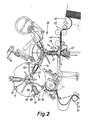
- Fig. 2
- eine Einzelheit der Vorrichtung nach Fig. 1 mit einem ersten und einem zweiten Falt-Revolver ebenfalls in Seitenansicht, bei vergrößertem Maßstab,
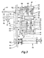
- Fig. 3
- einen Vertikal- bzw. Radialschnitt durch die Falt-Revolver nach Fig. 1,
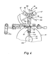
- Fig. 4
- Einzelheiten der Falt-Revolver, insbesondere des zweiten Falt-Revolvers, in Seitenansicht in einer Faltstellung,
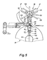
- Fig. 5
- eine Darstellung entsprechend Fig. 8 bei veränderter Position der Faltorgane,
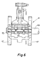
- Fig. 6
- die Einzelheit gemäß Fig. 4 und 5 in Draufsicht,
- Fig. 7
- den Steuermechanismus für die den Revolvertaschen zugeordneten Ausschieber in schematischer Seitenansicht in einer ersten Stellung, und
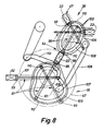
- Fig. 8
- den Mechanismus entsprechend Fig. 7 in einer zweiten Bewegungsstellung.
- Fig. 1
- a device for producing packs by wrapping objects in two blanks in their entirety in a schematic side view,
- Fig. 2
- 1 with a first and a second folding turret also in side view, on an enlarged scale,
- Fig. 3
- 2 shows a vertical or radial section through the folding turret according to FIG. 1,
- Fig. 4
- Details of the folding turret, in particular the second folding turret, in a side view in a folded position,
- Fig. 5
- 8 with a changed position of the folding members,
- Fig. 6
- 4 and 5 in plan view,
- Fig. 7
- the control mechanism for the pusher assigned to the turret pockets in a schematic side view in a first position, and
- Fig. 8
- 7 in a second movement position.
Das vorliegende Ausführungsbeispiel bezieht sich vor allem auf die Herstellung größerer Packungen aus mehreren einzelnen, kleineren Packungen, insbesondere Zigaretten-Packungen, die zu einer Packungsgruppe 22 zusammengefaßt sind und als Zigaretten-Stangen die Vorrichtung verlassen. Die Packungsgruppe 22 kann dabei alternativ in einen Karton-Zuschnitt und/oder in einen Folien-Zuschnitt bzw. in einen Papier-Zuschnitt eingehüllt werden. Ein Beispiel für einen nicht dargestellten Karton-Zuschnitt besteht aus einzelnen Flächenbereichen zur Bildung einer Oberwand, Unterwand, Seitenwänden sowie einem Schlauchlappen. Im Bereich der Unterwand sowie der Seitenwände befinden sich seitliche Schließlappen. In ähnlicher Weise kann ein Folien-Zuschnitt aufgebaut sein, nämlich ebenfalls mit Oberwand, Unterwand, dazwischen angeordneter erster Längs-Seitenwand sowie zwei randseitigen Schlauchlappen zur Bildung der gegenüberliegenden Längs-Seitenwand. Alle vorstehenden Zuschnitt-Teile sind seitlich mit Stirnlappen zur Ausbildung von Stirnwänden versehen. Der Karton-Zuschnitt ist vorzugsweise vorgefertigt, nämlich vorgestanzt, während der Folien-Zuschnitt von einer fortlaufenden Folienbahn 37 abgetrennt wird. Je nach Anforderung der Praxis wird die Packungsgruppe 22 in einen oder in beide der erwähnten Zuschnitte eingehüllt.The present exemplary embodiment relates above all to the production of larger packs from a plurality of individual, smaller packs, in particular cigarette packs, which are combined to form a
Die Packungsgruppe 22 durchläuft dabei in jedem Falle, also unabhängig von der Anzahl und Art der Zuschnitte, einen ersten Falt-Revolver 38 und danach einen zweiten Falt-Revolver 39. Aus letzterem werden die Packungen in Radialrichtung ausgeschoben und in eine im wesentlichen horizontale Abförderbahn 40 gebracht. An diese wiederum schließt ein aufrechter Packungsturm 41 an, in den die fertigen Packungen von unten her eingeschoben werden.The
Dem ersten Falt-Revolver 38 ist ein Zuschnittmagazin 42 zugeordnet zur Aufnahme eines Vorrats an Karton-Zuschnitten. An der Unterseite des Zuschnitt-Magazins 42 wird jeweils ein Karton-Zuschnitt durch einen Abroller 43 bekannter Bauart entnommen und in eine aufrechte Zuschnittbahn 44 eingeführt. Durch Transportwalzen 45 im Bereich dieser Zuschnittbahn 44 wird der Karton-Zuschnitt in aufrechter Ebene vor ein Mundstück 46 gefördert. Dieses ist dem ersten Falt-Revolver 38 derart vorgeordnet, daß in horizontaler Ebene die Packungsgruppe 22 durch das Mundstück 46 hindurch in eine Tasche 47 des Falt-Revolvers 38 einführbar ist. Der Karton-Zuschnitt wird beim Einschub der Packungsgruppe 22 in die Tasche 47 mitgenommen und U-förmig um die Packungsgruppe 22 herumgelegt. Beim Einschieben der Packungsgruppe in eine Revolvertasche sowie beim Transport längs der durch den Revolver vorgegebenen Förderstrecke erfolgt die Faltung des Karton-Zuschnitts und Umhüllung der Packungsgruppe durch diesen in an sich bekannter Weise mittels dem Faltrevolver 38 zugeordneter Faltorgane, auf deren genauere Beschreibung hier verzichtet werden kann. Der Falt-Revolver 38 wird ebenso wie der nachgeordnete Faltrevolver 39 taktweise bewegt.A
Im Bereich einer Übergabestation 64 wird die insoweit hergestellte Packung bzw. Packungsgruppe 22 aus der Tasche 47 des ersten Falt-Revolvers 38 ausgestoßen und zugleich in eine benachbarte Tasche 65 des zweiten Falt-Revolvers 39 eingeführt.In the area of a
Auch der Falt-Revolver 39 ist - wie der Falt-Revolver 38 - mit drei in gleichen Umfangsabständen voneinander angeordneten Taschen 65 bestückt. Diese bestehen aus einer im Querschnitt U-förmigen Taschenauskleidung 66, z. B. aus Blech. Auf der radial außenliegenden Seite ragen die Taschen 65 bzw. ragt die Taschenauskleidung 66 über das Profil des Revolvers hinweg. Ein aus seitlichen Revolverscheiben 67 bestehender Revolverkörper ist im Bereich der Taschen 65 mit radialen Ausnehmungen 68 versehen. Innerhalb derselben erstrecken sich die Taschenauskleidungen 66. Deren freier Rand ist mit einem in Umfangsrichtung abgewinkelten Stützschenkel 69 versehen. Diese sind unter einem spitzen Winkel zur Taschenauskleidung 66 angeordnet, also leicht radial nach innen gebogen. Die Stützschenkel dienen zur Aufnahme von Zuschnitt-Teilen, nämlich der Schlauchlappen eines dem zweiten Falt-Revolver 39 zugeführten Folien-Zuschnitts während einer Zwischenstellung desselben. Die Taschenauskleidung 66 erstreckt sich über die volle Breite des Falt-Revolvers 39, verbindet demnach die Revolverscheiben 67 miteinander. Zum Einhüllen der Packungsgruppe 22 in einen Folien-Zuschnitt wird dieser an den Außenumfang des Falt-Revolvers 39 angelegt, und zwar derart, daß der Folien-Zuschnitt annähernd mittig in bezug auf die betreffende Tasche 65 liegt. Der Folien-Zuschnitt wird dabei (lediglich) in einem in Drehrichtung des Falt-Revolvers 39 vorn liegenden Bereich erfaßt und durch Saugluft fixiert. Der Falt-Revolver 39 ist zu diesem Zweck an geeigneten Stellen mit Saugbohrungen 70 am Außenumfang versehen. Bei der Ausführung des Falt-Revolvers bzw. des Revolverkörpers mit zwei seitlichen Revolverscheiben 67 sind die Saugbohrungen 70 in beiden Revolverscheiben 67 in einander gegenüberliegenden Einsätzen 71 angeordnet. Der Folien-Zuschnitt wird demnach lediglich in vorderen Seitenbereichen auf dem Falt-Revolver 39 erfaßt und dadurch zwängungs- und faltenfrei gehalten. Die Saugbohrungen 70 sind über Saugleitungen mit einer zentralen Unterdruckquelle in geeigneter Weise verbunden.The
Die Umhüllung der Packungsgruppe 22 bzw. des bereits vorher angebrachten Karton-Zuschnitts durch den Folien-Zuschnitt erfolgt in einer im Prinzip bekannten Weise. Beim Einführen der Packungsgruppe 22 in die Tasche 65 im Bereich der Übergabestation 64 wird der am Außenumfang des Falt-Revolvers 39 bereitgehaltene Folien-Zuschnitt unter U-förmiger Umhüllung der Packungsgruppe 22 mitgenommen. Die über die Tasche 65 hinausragenden Zuschnitt-Teile werden dann durch geeignete Faltorgane an die Packungsgruppe angelegt. Die übereinandergefalteten Zuschnitt-Teile werden in an sich bekannter Weise miteinander verschweißt bzw. versiegelt.The wrapping of the
Die Falt-Revolver 38, 39 sind in besonderer Weise ausgebildet und angetrieben. In beiden Fällen sind radial bewegbare Ausschieber 96 und 97 im Bereich der Taschen 47 bzw. 65 vorgesehen In der nach innen gezogenen Ausgangsstellung bilden diese Ausschieber 96, 97 bzw. eine Querleiste 98, 99 derselben den radial innenliegenden Boden der Taschen 47 und 65. Die Querleiste 98, 99 ist an (zwei) Führungsstangen 100 bzw. 101 angebracht, die in radialen Führungsbohrungen 102, 103 einer Revolverwelle 104, 105 verschiebbar gelagert und abgestützt sind. Die gesteuerte Bewegung der Ausschieber 96, 97, insbesondere zum Ausschub von Packungen bzw. Packungsgruppen aus den zugeordneten Taschen, erfolgt durch Steuerscheiben 106, 107, die jedem Falt-Revolver 38, 39 zugeordnet sind (s. insbes. Fig. 7 und 8). In Kurvennuten 108, 109 dieser Steuerscheiben 106, 107 laufen Steuerrollen 110, die mit den Ausschiebern 96, 97 bzw. den Querleisten 98, 99 derselben über einen Ansatz 111 verbunden sind. Die Steuerscheiben 106, 107 werden drehend angetrieben, und zwar während der Stillstandsphase der Falt-Revolver 38, 39. Durch Drehbewegung der Steuerscheiben 106, 107 und durch entsprechende Gestaltung der Kurvennuten 108, 109 werden die Ausschieber 96, 97 während des Stillstands der Falt-Revolver 38, 39 In der einen oder anderen Richtung bewegt. Die beiden Steuerscheiben 106, 107 sind durch einen Lenker 128 getrieblich miteinander verbunden. Die Drehbewegung der beiden Steuerscheiben 106, 107 erfolgt durch einen an der Steuerscheibe 107 angeschlossenen und mit einem zentralen, nicht gezeigten Antrieb wirkverbundenen Lenker 112.The
Wie den Fig. 7 und 8 sehr deutlich entnommen werden kann, sind die Bewegungen der Ausschieber 96, 97 der beiden Falt-Revolver 38, 39 so aufeinander abgestimmt, daß im Bereich der Übergabestation 64 die Packungsgruppe 22 spielfrei zwischen den einander zugewandten Ausschiebern 96, 97 der beiden Falt-Revolver 38, 39 gehalten aus der Tasche 47 des ersten Falt-Revolvers 38 in die gegenüberliegende Tasche 65 des zweiten Falt-Revolvers 39 überführbar ist. Die Kurvennut 108 der dem ersten Falt-Revolver 38 zugeordneten Steuerscheibe 106 ist nach Art einer Ellipse mit einer Delle 129 ausgebildet. Die Kurvennut 109 der dem zweiten Falt-Revolver 39 zugeordneten Steuerscheibe 107 weist etwa die Kontur eines Schlüssellochs auf.7 and 8 can be seen very clearly, the movements of the
Die Falt-Revolver 38, 39 und eine dem zweiten Falt-Revolver 39 zugeordnete Schneidwalze 113 zum Abtrennen von Folien-Zuschnitten von der Folien-Bahn 37 werden durch ein gemeinsames Getriebe synchron und mit gleichen Umfangsgeschwindigkeiten angetrieben. Für den taktweisen Antrieb ist ein Schrittschaltgetriebe 114 geeigneter, bekannter Bauart vorgesehen. In Fig. 3 ist ein Schaltstern 115 als Abtriebsorgan dieses Schrittschaltgetriebes 114 gezeigt. Über Zahnräder 116, 117 wird die Revolverwelle 104 des Falt-Revolvers 38 angetrieben. Über weitere Zahnräder 118, 119 erfolgt - ausgehend vom Schaltstern 115 - der Antrieb der Revolverwelle 105 des Falt-Revolvers 39. Das Zahnrad 119 steht in getrieblicher Verbindung mit einem Zahnrad 120 für den Drehantrieb der Schneidwalze 113. Die Revolverwellen 104, 105 sowie ein der Schneidwalze 113 zugeordnetes Wellenstück 121 sind drehbar in einer gemeinsamen Maschinenwand 122 gelagert.The
Der Einheit Falt-Revolver 39/Schneidwalze 113 ist noch eine Zuführvorrichtung 123 für die Folienbahn 37 zugeordnet. Der Falt-Revolver 39 und die mit dem Umfang an den Umfang des vorgenannten Falt-Revolvers anschließende Schneidwalze 113 bilden eine Antriebseinheit, die hinsichtlich der Bewegung mit der Zuführvorrichtung 123 abgestimmt ist. Durch letztere wird jeweils ein Abschnitt der Folienbahn 37 zugefördert, der der Länge bzw. Breite (in Transportrichtung) des erforderlichen Folien-Zuschnitts zum Einhüllen der Packungsgruppe 22 entspricht. Da sich die vorliegende Erfindung nicht auf die Ausbildung der Zuführvorrichtung 123 sowie der dieser vorgeschalteten Aggregate beziehen soll, erübrigt sich eine nähere Beschreibung dieser VorrichtungsteileThe
Zusammenfassend stellt sich die erfindungsgemäße Konstruktion als besonders vorteilhaft für die Entfernung langgestreckter Gegenstände, z. B. Zigaretten-Stangen, aus Taschen von Falt-Revolvern einer Verpackungs-Maschine dar. Durch die erfindungsgemäßen Ausschieber 96, 98 bzw.97, 99 werden die langgestreckten Gegenstände auf ihrer vollen Länge vorzugsweise der schmalen Seitenfläche in den Taschen 47 bzw. 65 der Falt-Revolver 38 bzw. 39 erfaßt und ausge schoben. Eine ungleichmäßige Beaufschlagung und ein dadurch bedingter Versatz der Einzelgegenstände bzw. Zigarettenpackungen beim Ausschieben der Packungsgruppe 22 aus den Taschen kann nicht auftreten.In summary, the construction according to the invention is particularly advantageous for the removal of elongated objects, e.g. B. cigarette sticks, from pockets of folding turrets of a packaging machine. By the
Abschließend sei noch darauf hingewiesen, daß die seitlichen Scheiben 67 des Falt-Revolvers 39 gleichzeitig zur seitlichen Begrenzung der Revolver-Taschen 65 dienen. Die Revolver-Taschen 65 sind also ausschließlich in radialer Richtung nach außen offen ausgebildet.Finally, it should also be pointed out that the
Ferner sei an dieser Stelle nochmals festgehalten, daß die Erfindung für eine Vorrichtung sowohl mit einem oder mehreren Falt-Revolvern der genannten Art Anwendung finden kann.It should also be noted at this point that the invention can be used for a device with one or more folding turrets of the type mentioned.
Claims (8)
- Apparatus for producing packs by wrapping articles in at least one blank, especially for producing large packs composed of pack groups, the articles or pack groups (22) passing, so as to be wrapped in blanks, through at least one wrapping and folding member in the form of a folding turret (38 or 39) with several pockets (47 or 65) open in a radial direction, each for receiving one article or one pack group (22) together with a blank, and each pocket (47 or 65) having assigned to it a radially movable pushing-out device (96 or 97) which forms the bottom of the pocket and by which the articles or pack groups (22) can be pushed out of the particular pocket (47 or 65), and an actuating member for the timed actuation of the pushing-out device being provided for the pushing-out device, characterized in that the actuating member comprises at least one rotary-driven control member (control disc 106 or 107) which controls the movement cycle of the pushing-out device (96 or 97) during actuation and to which each pushing-out device (96 or 97) is permanently connected via a control means (control rollers 110) respectively assigned to it.
- Apparatus according to Claim 1, characterized in that the control disc (106 or 107) has a curved groove (108 or 109), in which run the control rollers (110) which are connected to the pushing-out devices (96 or 97) or to the transverse strips (98 or 99) of the latter, each preferably via an extension (111).
- Apparatus according to Claim 1 or 2, characterized in that the control disc (106 or 107) is driven to rotate only when the associated folding turret (38 or 39) is stationary.
- Apparatus according to one of Claims 1 to 3, characterized in that the pushing-out devices (96 or 97) each possess at least two guide rods (100 or 101) which are at a distance from one another and extend parallel to one another and which are mounted displaceably and supported in radial guide bores (102 or 103) in the turret shaft (104 or 105).
- Apparatus according to one of Claims 1 to 4, characterized in that the pushing-out devices (96 or 97) have at each of their free ends, to form the bottom of the turret pockets (47 or 65), a supporting plate, supporting strip (98 or 99) or the like extending approximately parallel to the turret axis and essentially over the entire length of the turret pocket (47 or 65).
- Apparatus according to one of Claims 1 to 5, with two folding turrets (38,39) associated with one another, each with several pockets (47, 65) open in a radial direction, each receiving one article or one pack group (22) together with a blank, characterized in that the article or the pack group (22) can be pushed from the first folding turret (38), by being pushed radially out of a pocket (47) of the latter, directly into a pocket (65) of the associated second folding turret (39), if appropriate at the same time being wrapped in a (second) blank, and during the transfer from the pocket (47) of the first folding turret (38) into the facing pocket (65) of the second folding turret (39) the pack group is retained between the pushing-out devices (96, 97) assigned to these pockets.
- Apparatus according to Claim 6, characterized in that the pushing-out devices (96, 97) of the two folding turrets (38, 39) or their control discs (106, 107) are connected to one another in transmission terms, preferably by means of a link (128).
- Apparatus according to Claim 7, characterized in that the rotary movement of the two control discs (106, 107) is executed by means of a central drive (link 112) engaging on only one control disc (107), preferably when the two folding turrets (38, 39) are stationary.
Applications Claiming Priority (2)
| Application Number | Priority Date | Filing Date | Title |
|---|---|---|---|
| DE3433428 | 1984-09-12 | ||
| DE19843433428 DE3433428A1 (en) | 1984-09-12 | 1984-09-12 | DEVICE FOR PRODUCING PACKS, IN PARTICULAR CIGARETTE RODS |
Publications (3)
| Publication Number | Publication Date |
|---|---|
| EP0174591A2 EP0174591A2 (en) | 1986-03-19 |
| EP0174591A3 EP0174591A3 (en) | 1987-05-27 |
| EP0174591B1 true EP0174591B1 (en) | 1991-03-27 |
Family
ID=6245186
Family Applications (1)
| Application Number | Title | Priority Date | Filing Date |
|---|---|---|---|
| EP85111099A Expired - Lifetime EP0174591B1 (en) | 1984-09-12 | 1985-09-03 | Device for making packages, especially cigarette cartons |
Country Status (6)
| Country | Link |
|---|---|
| US (1) | US4646508A (en) |
| EP (1) | EP0174591B1 (en) |
| JP (1) | JPH0662142B2 (en) |
| BR (1) | BR8504393A (en) |
| CA (1) | CA1305654C (en) |
| DE (2) | DE3433428A1 (en) |
Cited By (1)
| Publication number | Priority date | Publication date | Assignee | Title |
|---|---|---|---|---|
| DE4200854B4 (en) * | 1992-01-15 | 2005-07-07 | The Procter & Gamble Company, Cincinnati | Method for producing and sealing soft packs for small objects, for example for a stack of pulp cloths and a machine installation for carrying out this method |
Families Citing this family (13)
| Publication number | Priority date | Publication date | Assignee | Title |
|---|---|---|---|---|
| IT1200208B (en) * | 1986-09-24 | 1989-01-05 | Gd Spa | DEVICE FOR FEEDING STAGNOLA CUTS IN A CIGARETTE PACKING MACHINE |
| IT1246840B (en) * | 1990-07-17 | 1994-11-28 | Gd Spa | WRAPPING MACHINE OF SUBSTANTIALLY PARALLELEPIPED BOXING ELEMENTS. |
| DE4200921B4 (en) * | 1992-01-16 | 2005-12-22 | Focke & Co.(Gmbh & Co. Kg) | Method for producing packaging from two part packs and device for producing such packagings |
| US5452561A (en) * | 1993-03-02 | 1995-09-26 | Super Products Inc. | Package banding machine |
| IT1285575B1 (en) * | 1996-03-01 | 1998-06-18 | Gd Spa | METHOD AND UNIT FOR THE BENDING OF LONG Wrapping BLANK PRE-WEAKENED BENDING LINES. |
| IT1285576B1 (en) * | 1996-03-01 | 1998-06-18 | Gd Spa | CONVEYOR GROUP OF PRODUCTS |
| EP0820929A1 (en) * | 1996-07-26 | 1998-01-28 | G.D Societa' Per Azioni | Packet wrapping unit |
| DE19716930A1 (en) * | 1997-04-23 | 1998-10-29 | Focke & Co | Device for producing preferably large packs |
| DE10000798A1 (en) * | 2000-01-11 | 2001-07-12 | Focke & Co | Device for producing packs of cigarettes |
| DE102004046576A1 (en) | 2004-09-23 | 2006-03-30 | Focke & Co.(Gmbh & Co. Kg) | Device for wrapping groups of packages |
| ES2712063T3 (en) * | 2015-02-10 | 2019-05-09 | Jt Int Sa | Procedure and apparatus for marking a package of articles and the resulting package |
| ITUB20160604A1 (en) * | 2016-02-09 | 2017-08-09 | Ima Spa | UNITS AND METHOD FOR PLACING OBJECTS WITHIN BOXES. |
| ITUA20161853A1 (en) * | 2016-03-21 | 2017-09-21 | Gd Spa | Unit and method of wrapping to fold a sheet of wrapping around an article |
Citations (3)
| Publication number | Priority date | Publication date | Assignee | Title |
|---|---|---|---|---|
| DE1238378B (en) * | 1961-11-09 | 1967-04-06 | Alfred Schmermund | Method and device for the production of multiple packs from individual cigarette packs |
| US3380227A (en) * | 1964-02-20 | 1968-04-30 | Molins Organisation Ltd | Packing or wrapping machine of the mould wheel type |
| EP0030359A1 (en) * | 1979-12-07 | 1981-06-17 | FOCKE & CO. | Apparatus for packaging cigarettes or the like |
Family Cites Families (18)
| Publication number | Priority date | Publication date | Assignee | Title |
|---|---|---|---|---|
| US1359181A (en) * | 1920-11-16 | Wrapping-machine | ||
| US546193A (en) * | 1895-09-10 | Wrapping-machine | ||
| US645016A (en) * | 1899-09-13 | 1900-03-06 | Henry Rose | Wrapping-machine. |
| US788494A (en) * | 1903-12-26 | 1905-04-25 | Adolfo Moeller & Co | Cigarette-packing machine. |
| US990532A (en) * | 1909-09-04 | 1911-04-25 | Wrights Automatic Tobacco Packing Machine Company | Labeling and stamping machine. |
| US1351025A (en) * | 1918-09-27 | 1920-08-31 | Diamond Match Co | Package-wrapping machine |
| US1485598A (en) * | 1921-02-08 | 1924-03-04 | Croxford Frederick Charles | Packing and wrapping up articles for transit and storage |
| US1814696A (en) * | 1929-07-12 | 1931-07-14 | George I Hohl | Wrapping and banding machine |
| US3053024A (en) * | 1961-04-07 | 1962-09-11 | Wexler Joseph | Machine for folding and wrapping paper bundles |
| DE1511838A1 (en) * | 1967-03-10 | 1970-04-02 | Verpackungs Und Schokoladenmas | Device for producing a multipack |
| GB1233900A (en) * | 1967-10-17 | 1971-06-03 | ||
| DE2032184A1 (en) * | 1969-07-15 | 1971-02-18 | Haum Werke, Korber & Co KG, 2050 Hamburg | Device for producing and filling soft packs |
| DE2127294A1 (en) * | 1971-06-02 | 1972-12-14 | Hauni-Werke Körber & Co KG, 2050 Hamburg | Device for separating sections of wrapping material |
| DE2127706A1 (en) * | 1971-06-04 | 1972-12-14 | Hauni-Werke Körber & Co KG, 2050 Hamburg | Revolver of a cigarette packing machine |
| IT1000890B (en) * | 1973-11-21 | 1976-04-10 | Gd Spa | FAST CIGARETTES PACKAGING MACHINE |
| US4358920A (en) * | 1980-06-04 | 1982-11-16 | Lotte Co., Ltd. | Apparatus for wrapping a sheet article |
| DE3123496A1 (en) * | 1981-06-13 | 1983-01-13 | Focke & Co, 2810 Verden | DEVICE FOR PRODUCING PACKS, IN PARTICULAR CIGARETTE RODS |
| DE3348487C2 (en) * | 1983-09-14 | 1998-05-20 | Focke & Co | Packaging machine for cigarettes |
-
1984
- 1984-09-12 DE DE19843433428 patent/DE3433428A1/en not_active Withdrawn
-
1985
- 1985-09-03 DE DE8585111099T patent/DE3582290D1/en not_active Expired - Lifetime
- 1985-09-03 EP EP85111099A patent/EP0174591B1/en not_active Expired - Lifetime
- 1985-09-06 CA CA000490127A patent/CA1305654C/en not_active Expired - Lifetime
- 1985-09-09 US US06/773,726 patent/US4646508A/en not_active Expired - Lifetime
- 1985-09-11 JP JP60199640A patent/JPH0662142B2/en not_active Expired - Fee Related
- 1985-09-11 BR BR8504393A patent/BR8504393A/en not_active IP Right Cessation
Patent Citations (3)
| Publication number | Priority date | Publication date | Assignee | Title |
|---|---|---|---|---|
| DE1238378B (en) * | 1961-11-09 | 1967-04-06 | Alfred Schmermund | Method and device for the production of multiple packs from individual cigarette packs |
| US3380227A (en) * | 1964-02-20 | 1968-04-30 | Molins Organisation Ltd | Packing or wrapping machine of the mould wheel type |
| EP0030359A1 (en) * | 1979-12-07 | 1981-06-17 | FOCKE & CO. | Apparatus for packaging cigarettes or the like |
Cited By (1)
| Publication number | Priority date | Publication date | Assignee | Title |
|---|---|---|---|---|
| DE4200854B4 (en) * | 1992-01-15 | 2005-07-07 | The Procter & Gamble Company, Cincinnati | Method for producing and sealing soft packs for small objects, for example for a stack of pulp cloths and a machine installation for carrying out this method |
Also Published As
| Publication number | Publication date |
|---|---|
| BR8504393A (en) | 1986-07-08 |
| DE3582290D1 (en) | 1991-05-02 |
| JPH0662142B2 (en) | 1994-08-17 |
| US4646508A (en) | 1987-03-03 |
| DE3433428A1 (en) | 1986-03-20 |
| CA1305654C (en) | 1992-07-28 |
| JPS6169517A (en) | 1986-04-10 |
| EP0174591A2 (en) | 1986-03-19 |
| EP0174591A3 (en) | 1987-05-27 |
Similar Documents
| Publication | Publication Date | Title |
|---|---|---|
| EP1067049B1 (en) | Method and device for making packs | |
| EP0197368B1 (en) | Method and apparatus for packaging cigarettes in particular | |
| EP0137334B1 (en) | Device for making packages, especially cigarette cartons | |
| DE2840850C2 (en) | ||
| EP0386524B1 (en) | Device for packaging objects of different size | |
| EP2509889B1 (en) | Method and apparatus for producing packs, in particular for cigarettes | |
| EP0275481B1 (en) | Method and device for packaging paper handkerchiefs | |
| EP0551660B1 (en) | Method for producing a package composed of two individual packets | |
| DE3738102C2 (en) | Device for feeding blanks to a packaging unit | |
| EP1448443B1 (en) | Method and device for producing hard packs for cigarettes | |
| EP0174591B1 (en) | Device for making packages, especially cigarette cartons | |
| EP1829783B1 (en) | Device and method for producing double packages | |
| DE2440006A1 (en) | PROCESS AND DEVICE FOR MANUFACTURING AND FILLING FOLDABLE BOXES FROM FOLDABLE MATERIAL, PREFERABLY FOR CIGARETTES | |
| DE2350111A1 (en) | FAST-RUNNING BOTTOM FOLDING PACKER | |
| DE3536791C2 (en) | ||
| EP0304736B1 (en) | Method and device for enveloping, especially cigarette packages | |
| EP0391118B1 (en) | Method and device for making (cigarette) packages | |
| DE10310451A1 (en) | Method and device for producing packages from at least two partial packages | |
| EP0418687B1 (en) | Bottom-folding packaging machine | |
| EP0854098A2 (en) | Package, especially for a group of cigarette packages and apparatus for making it | |
| DE3804946A1 (en) | METHOD AND DEVICE FOR SEPARATING LEVEL PARTS | |
| CH440105A (en) | Double lane cross packer | |
| DE3204620A1 (en) | Method and device for the production of matchbox liners | |
| DE8223088U1 (en) | COLLECTING AND STACKING DEVICE FOR PAPER DIAPERS | |
| DE1461932B (en) | Device for packing cigarettes or the like |
Legal Events
| Date | Code | Title | Description |
|---|---|---|---|
| PUAI | Public reference made under article 153(3) epc to a published international application that has entered the european phase |
Free format text: ORIGINAL CODE: 0009012 |
|
| AK | Designated contracting states |
Kind code of ref document: A2 Designated state(s): DE FR GB IT |
|
| PUAL | Search report despatched |
Free format text: ORIGINAL CODE: 0009013 |
|
| AK | Designated contracting states |
Kind code of ref document: A3 Designated state(s): DE FR GB IT |
|
| 17P | Request for examination filed |
Effective date: 19871111 |
|
| 17Q | First examination report despatched |
Effective date: 19880913 |
|
| GRAA | (expected) grant |
Free format text: ORIGINAL CODE: 0009210 |
|
| AK | Designated contracting states |
Kind code of ref document: B1 Designated state(s): DE FR GB IT |
|
| GBT | Gb: translation of ep patent filed (gb section 77(6)(a)/1977) | ||
| REF | Corresponds to: |
Ref document number: 3582290 Country of ref document: DE Date of ref document: 19910502 |
|
| ITF | It: translation for a ep patent filed | ||
| ET | Fr: translation filed | ||
| PLBE | No opposition filed within time limit |
Free format text: ORIGINAL CODE: 0009261 |
|
| STAA | Information on the status of an ep patent application or granted ep patent |
Free format text: STATUS: NO OPPOSITION FILED WITHIN TIME LIMIT |
|
| 26N | No opposition filed | ||
| PGFP | Annual fee paid to national office [announced via postgrant information from national office to epo] |
Ref country code: FR Payment date: 19940909 Year of fee payment: 10 |
|
| PG25 | Lapsed in a contracting state [announced via postgrant information from national office to epo] |
Ref country code: FR Effective date: 19960531 |
|
| REG | Reference to a national code |
Ref country code: FR Ref legal event code: ST |
|
| REG | Reference to a national code |
Ref country code: GB Ref legal event code: IF02 |
|
| PGFP | Annual fee paid to national office [announced via postgrant information from national office to epo] |
Ref country code: GB Payment date: 20020828 Year of fee payment: 18 |
|
| PGFP | Annual fee paid to national office [announced via postgrant information from national office to epo] |
Ref country code: DE Payment date: 20020927 Year of fee payment: 18 |
|
| PG25 | Lapsed in a contracting state [announced via postgrant information from national office to epo] |
Ref country code: GB Free format text: LAPSE BECAUSE OF NON-PAYMENT OF DUE FEES Effective date: 20030903 |
|
| PG25 | Lapsed in a contracting state [announced via postgrant information from national office to epo] |
Ref country code: DE Free format text: LAPSE BECAUSE OF NON-PAYMENT OF DUE FEES Effective date: 20040401 |
|
| GBPC | Gb: european patent ceased through non-payment of renewal fee |