EP0174145B1 - Frame routing apparatus - Google Patents
Frame routing apparatus Download PDFInfo
- Publication number
- EP0174145B1 EP0174145B1 EP85306025A EP85306025A EP0174145B1 EP 0174145 B1 EP0174145 B1 EP 0174145B1 EP 85306025 A EP85306025 A EP 85306025A EP 85306025 A EP85306025 A EP 85306025A EP 0174145 B1 EP0174145 B1 EP 0174145B1
- Authority
- EP
- European Patent Office
- Prior art keywords
- router
- stem
- head
- axis
- frame member
- Prior art date
- Legal status (The legal status is an assumption and is not a legal conclusion. Google has not performed a legal analysis and makes no representation as to the accuracy of the status listed.)
- Expired
Links
- 238000005520 cutting process Methods 0.000 claims abstract description 11
- 238000000034 method Methods 0.000 claims description 8
- 238000000465 moulding Methods 0.000 claims description 4
- 238000006073 displacement reaction Methods 0.000 claims description 2
- 238000005304 joining Methods 0.000 claims description 2
- 230000013011 mating Effects 0.000 claims 2
- 238000003780 insertion Methods 0.000 description 6
- 230000037431 insertion Effects 0.000 description 6
- 230000000712 assembly Effects 0.000 description 2
- 238000000429 assembly Methods 0.000 description 2
- 239000000463 material Substances 0.000 description 2
- 239000004033 plastic Substances 0.000 description 2
- 239000004743 Polypropylene Substances 0.000 description 1
- 230000001154 acute effect Effects 0.000 description 1
- 238000005452 bending Methods 0.000 description 1
- 238000004519 manufacturing process Methods 0.000 description 1
- -1 polypropylene Polymers 0.000 description 1
- 229920001155 polypropylene Polymers 0.000 description 1
- 239000002023 wood Substances 0.000 description 1
Images


Classifications
-
- A—HUMAN NECESSITIES
- A47—FURNITURE; DOMESTIC ARTICLES OR APPLIANCES; COFFEE MILLS; SPICE MILLS; SUCTION CLEANERS IN GENERAL
- A47G—HOUSEHOLD OR TABLE EQUIPMENT
- A47G1/00—Mirrors; Picture frames or the like, e.g. provided with heating, lighting or ventilating means
- A47G1/06—Picture frames
- A47G1/10—Corner clips or corner-connecting appliances for frames
- A47G1/101—Corner clips or corner-connecting appliances for frames for insertion within frame members
-
- B—PERFORMING OPERATIONS; TRANSPORTING
- B27—WORKING OR PRESERVING WOOD OR SIMILAR MATERIAL; NAILING OR STAPLING MACHINES IN GENERAL
- B27F—DOVETAILED WORK; TENONS; SLOTTING MACHINES FOR WOOD OR SIMILAR MATERIAL; NAILING OR STAPLING MACHINES
- B27F1/00—Dovetailed work; Tenons; Making tongues or grooves; Groove- and- tongue jointed work; Finger- joints
- B27F1/005—Machines or devices for working mitre joints with uneven ends
-
- B—PERFORMING OPERATIONS; TRANSPORTING
- B27—WORKING OR PRESERVING WOOD OR SIMILAR MATERIAL; NAILING OR STAPLING MACHINES IN GENERAL
- B27G—ACCESSORY MACHINES OR APPARATUS FOR WORKING WOOD OR SIMILAR MATERIALS; TOOLS FOR WORKING WOOD OR SIMILAR MATERIALS; SAFETY DEVICES FOR WOOD WORKING MACHINES OR TOOLS
- B27G13/00—Cutter blocks; Other rotary cutting tools
- B27G13/12—Cutter blocks; Other rotary cutting tools for profile cutting
- B27G13/14—Cutter blocks; Other rotary cutting tools for profile cutting for cutting grooves or tenons
-
- F—MECHANICAL ENGINEERING; LIGHTING; HEATING; WEAPONS; BLASTING
- F16—ENGINEERING ELEMENTS AND UNITS; GENERAL MEASURES FOR PRODUCING AND MAINTAINING EFFECTIVE FUNCTIONING OF MACHINES OR INSTALLATIONS; THERMAL INSULATION IN GENERAL
- F16B—DEVICES FOR FASTENING OR SECURING CONSTRUCTIONAL ELEMENTS OR MACHINE PARTS TOGETHER, e.g. NAILS, BOLTS, CIRCLIPS, CLAMPS, CLIPS OR WEDGES; JOINTS OR JOINTING
- F16B12/00—Jointing of furniture or the like, e.g. hidden from exterior
- F16B12/10—Jointing of furniture or the like, e.g. hidden from exterior using pegs, bolts, tenons, clamps, clips, or the like
- F16B12/12—Jointing of furniture or the like, e.g. hidden from exterior using pegs, bolts, tenons, clamps, clips, or the like for non-metal furniture parts, e.g. made of wood, of plastics
- F16B12/24—Jointing of furniture or the like, e.g. hidden from exterior using pegs, bolts, tenons, clamps, clips, or the like for non-metal furniture parts, e.g. made of wood, of plastics using separate pins, dowels, or the like
-
- F—MECHANICAL ENGINEERING; LIGHTING; HEATING; WEAPONS; BLASTING
- F16—ENGINEERING ELEMENTS AND UNITS; GENERAL MEASURES FOR PRODUCING AND MAINTAINING EFFECTIVE FUNCTIONING OF MACHINES OR INSTALLATIONS; THERMAL INSULATION IN GENERAL
- F16B—DEVICES FOR FASTENING OR SECURING CONSTRUCTIONAL ELEMENTS OR MACHINE PARTS TOGETHER, e.g. NAILS, BOLTS, CIRCLIPS, CLAMPS, CLIPS OR WEDGES; JOINTS OR JOINTING
- F16B5/00—Joining sheets or plates, e.g. panels, to one another or to strips or bars parallel to them
- F16B5/0004—Joining sheets, plates or panels in abutting relationship
- F16B5/0032—Joining sheets, plates or panels in abutting relationship by moving the sheets, plates, or panels or the interlocking key parallel to the abutting edge
- F16B5/0052—Joining sheets, plates or panels in abutting relationship by moving the sheets, plates, or panels or the interlocking key parallel to the abutting edge the interlocking key acting as a dovetail-type key
-
- A—HUMAN NECESSITIES
- A47—FURNITURE; DOMESTIC ARTICLES OR APPLIANCES; COFFEE MILLS; SPICE MILLS; SUCTION CLEANERS IN GENERAL
- A47B—TABLES; DESKS; OFFICE FURNITURE; CABINETS; DRAWERS; GENERAL DETAILS OF FURNITURE
- A47B2230/00—Furniture jointing; Furniture with such jointing
- A47B2230/0055—Biscuits including formed staples or the like
- A47B2230/0062—Connectors for adjacent furniture parts, the mouths of the grooves for said connectors being on the join lines of said furniture parts
-
- Y—GENERAL TAGGING OF NEW TECHNOLOGICAL DEVELOPMENTS; GENERAL TAGGING OF CROSS-SECTIONAL TECHNOLOGIES SPANNING OVER SEVERAL SECTIONS OF THE IPC; TECHNICAL SUBJECTS COVERED BY FORMER USPC CROSS-REFERENCE ART COLLECTIONS [XRACs] AND DIGESTS
- Y10—TECHNICAL SUBJECTS COVERED BY FORMER USPC
- Y10T—TECHNICAL SUBJECTS COVERED BY FORMER US CLASSIFICATION
- Y10T407/00—Cutters, for shaping
- Y10T407/19—Rotary cutting tool
- Y10T407/1906—Rotary cutting tool including holder [i.e., head] having seat for inserted tool
- Y10T407/1908—Face or end mill
-
- Y—GENERAL TAGGING OF NEW TECHNOLOGICAL DEVELOPMENTS; GENERAL TAGGING OF CROSS-SECTIONAL TECHNOLOGIES SPANNING OVER SEVERAL SECTIONS OF THE IPC; TECHNICAL SUBJECTS COVERED BY FORMER USPC CROSS-REFERENCE ART COLLECTIONS [XRACs] AND DIGESTS
- Y10—TECHNICAL SUBJECTS COVERED BY FORMER USPC
- Y10T—TECHNICAL SUBJECTS COVERED BY FORMER US CLASSIFICATION
- Y10T407/00—Cutters, for shaping
- Y10T407/19—Rotary cutting tool
- Y10T407/1946—Face or end mill
- Y10T407/1948—Face or end mill with cutting edge entirely across end of tool [e.g., router bit, end mill, etc.]
Definitions
- This invention relates generally to routers and to the production of corner brackets for holding frame parts in assembled condition using such routers. More particularly, it concerns apparatus to produce recesses in frame parts, which will receive a bracket to lock the parts together.
- One object of the invention is to provide a router for cutting an L-shape groove in elongated frame members adapted to have their ends joined in L-shaped assembly by an L-shaped bracket of the particular shape referred to.
- AT-A-291,520 discloses a router for cutting grooves, the router comprising, an elongated cutter stem having an axis about which the stem is rotatable, and a cutter head at the end of the stem, integral therewith and shaped for cutting an enlargement in the groove.
- the invention provides a router characterised in that the head and stem have substantially parallelogram cross sections in planes normal to the axis.
- the head parallelogram cross sections are larger than the stem parallelogram cross sections; the head and stem parallelogram cross sections have substantially parallel corresponding sides; and the two sides of the stem are closer to the axis of rotation than most of the corresponding sides of the head, so that space is provided to receive cuttings as the groove is formed in each frame member. Also, two sides of the head are convexly curved.
- AT-A-291,520 also discloses the use of a router for cutting right-angled grooves in frame assemblies and the joining of such frame assemblies by insert members.
- the router of the present invention may be used in methods as claimed in claims 11 to 14.
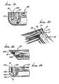
- the illustrated lock-up corner bracket 10 is shown to include legs 11 and 12 that extend in planes 13 and 14 which define a corner angle a.
- the latter is typically about 90°, but may vary somewhat from 90°, as for example between 85° and 95°.
- the leg 11 has opposite sides 11 a and 11 which are longitudinally elongated in the Z direction indicated by arrow Z, and leg 12 has opposite sides 12a and 12b which are also elongated in the Z direction.
- Plane 13 is an X-Z plane
- plane 14 is an X-Y plane. Note inside and outside corners 15 and 16 of leg intersections.
- the legs have terminal enlargements that are also elongated in parallel directions (parallel to the Z-direction) of forward insertion of the legs relatively into recesses formed in the frame parts, for retaining such parts in assembled relation or conditions.
- the enlargements 17 and 18 are integral with legs 11 and 12, respectively, and are columnar, the planes 13 and 14 bisecting the enlargements. Note that the columnar enlargements have lengths approximately equal to the Z-direction lengths of the legs, and they have generally cylindrical outer surfaces throughout such lengths.
- the forwardmost end portions of the legs and enlargements are forwardly tapered (see tapers 11c and 11d, 12c, 17a, and 18a) to assist in their initial slide receptions into the corresponding recesses (leg and column) indicated at 19-22 in frame parts 23 and 24.
- Such slide reception is close in all such recesses, whereby the frame parts are rigidly positioned, as assembled, with 45° angled surfaces 23a and 24a held in face-to-face, sturdy interengagement.
- This is enhanced due to the columnar enlargements having cross-sectional dimensions "t,” exceeding the thickness dimension "tz" of the legs, as indicated in Figure 10.
- Figure 12 shows an easy assembled mode (made possible by the invention) wherein the leg 12 and column 18 are first inserted into the recesses 20 and 22 in parts 24; and then the leg 11 and column 17 are relatively inserted into the recesses 19 and 21 in part 23 causing faces 23a and 24a to slide against one another until the assembly is completed with the tops of the legs and columns flush with the surfaces 23a and 24a of the frame parts 23 and 24.
- the latter frame parts may be those of a picture frame, with a bracket 10 easily assembled to the frame parts at each of the four corners of the picture frame. This enables the frame parts to be incorporated in a small kit suitable for mailing, so that the ultimate user can quickly assemble the frame using the improved corner brackets.
- An additional feature is the provision of a barb or barbs on one or both legs of the bracket. See for example, barbs 30 and 31 on legs 11 and 12 in Figure 8.
- Such barbs integral with the bracket project outwardly from faces 11 a and 12a, with forward taper, to compress the recess walls (see for example recess wall 20a in Figure 11) during bracket insertion, and grip such walls to resist bracket removal from the recesses (i.e. to ensure that the parts 23 and 24 will remain assembled).
- Figures 13 and 14 show details of a recess 19 prior to bracket insertion therein. Note that the recess terminates at point 19e, at a considerable spacing "t 3 " from the bottom 23c of the frame part, so that the structural strength of the latter is not undesirably reduced (i.e. region 23d of the frame part remains unslotted so that sections 23e and 23f are not undesirably spread apart during bracket insertion). Sections 23e and 23f each have substantially constant width along their length, for maximum strength, as enabled by the insertion.
- the frame parts may consist of wood or plastic material, and the bracket may typically consist of plastic material, as for example, moulded polypropylene.
- the router 100 is constructed to cut an L-shape groove in elongated frame members (shown for example at 101 in tooling mounted position in Figures 6-8) so that such members may have their ends joined in L-shaped assembly by the L-shaped bracket 10 described above in Figures 8 to 14.
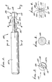
- the metallic router 100 comprises an elongated cutter stem 102 having an axis 103 about which the stem is rotatable, as by driver 104 driven by motor 105.
- Driver 104 suitably mounts the router, as via an elongated and cylindrical stem extension 102a.
- the stem has substantially parallelogram cross sections in planes normal to the axis 103, and along the stem length.
- the router also has a head 106 integral with and at the end of the stem, the head also having substantially parallelogram cross sections in planes normal to axis 103. Typically, the head cross sections are larger than the stem cross sections.
- the head and stem parallelogram cross sections have parallel corresponding sides.
- the stem cross section sides 110a-113a correspond to head cross section sides 110-113, sides 110a and 110 being parallel (but side 110a being closer to axis 103 than most of sides 110); sides 111a and 111 being parallel (but side 111a being closer to axis 103 than most of the sides 111); sides 112a and 112 being parallel and in the same plane; and sides 113a and 113 being parallel and in the same plane.
- chips or cuttings fill into the spaces adjacent sides 110a and 111a, and are pulled out when the cutter is sidewardly removed from the frame member.
- sharp acute angled cutting edges are formed at 140,141,142 and 143.
- the head typically forms two generally outwardly convex outer surfaces indicated at 114 and 115, and coincident with cross section sides 110 and 111, respectively.
- Surfaces 114 and 115 merge with stem surfaces 106 and 107, as at locations 114a and 115a.
- the head also has a flat terminal 120 remote from the stem, and in a flat plane normal to axis 103.
- means is provided to rotate the router about axis 103, and includes the router driver 104 in which the router stem extension 102a is gripped or releasably clamped.
- a motor 105 rotates the driver.
- Means is also provided to hold the two elongated frame members 101 in parallel, longitudinally elongated, laterally spaced relation, to be cut by the router head and stem as the router is displaced laterally (see arrows 121) in opposite directions, and relative to the frame member ends 101a a presented to the router.
- the frame member holder means may advantageously and typically include a base 122 having spaced shoulders to position the frame members, and mouldings associated with the base. See for example, the two elongated grooves 127a each having opposite, laterally spaced shoulders 123 and 124, between which frame members 101 are fitted. Stops 125 position the ends 126 of the frame members. Frame member mouldings are associated with the base, to hold the members in position as shown, during the routing operation. See for example, the thin metallic mouldings having first portions 126a extending beneath the frame members; second position which curve upwardly at 126b into contact with walls 124, and upper portions extending above the members and projecting back downwardly at 126c.
- the base 122 may be displaced laterally (see arrows 121) to cause the router to sidewardly penetrate the ends of the frame members, forming grooves or recesses therein as shown and described in Figures 8to 14.
- the depth of the groove is indicated at 130 in Figure 6, and is controlled by stop associated with the base and router driver.
- stop 131 on the base engages stop 132 integral with the holder for motor 105, indicated at 133, at which time the router has sidewardly penetrated the frame member to depth 130; and as the base is moved to the right, stop 131a on the base engages stop 134 integral with the motor holder.
- Suitable laterally elongated guide means for guiding lateral movement of the base is indicated at 137, in Figure 5.
Abstract
Description
- This invention relates generally to routers and to the production of corner brackets for holding frame parts in assembled condition using such routers. More particularly, it concerns apparatus to produce recesses in frame parts, which will receive a bracket to lock the parts together.
- There is a continuing need for simple, effective low cost and easily inserted means to hold frame parts in corner assembled condition. The prior use of staples for this purpose is objectionable due to the need for a staple gun and lack of staple strength sufficient to hold the frame parts together, against relative bending displacement.
- Further, there is need for simple, rugged, and easily operated means to form the above- described recesses in frame members, to receive L-shaped brackets.
- One object of the invention is to provide a router for cutting an L-shape groove in elongated frame members adapted to have their ends joined in L-shaped assembly by an L-shaped bracket of the particular shape referred to.
- AT-A-291,520 discloses a router for cutting grooves, the router comprising, an elongated cutter stem having an axis about which the stem is rotatable, and a cutter head at the end of the stem, integral therewith and shaped for cutting an enlargement in the groove.
- The invention provides a router characterised in that the head and stem have substantially parallelogram cross sections in planes normal to the axis.
- In one embodiment, the head parallelogram cross sections are larger than the stem parallelogram cross sections; the head and stem parallelogram cross sections have substantially parallel corresponding sides; and the two sides of the stem are closer to the axis of rotation than most of the corresponding sides of the head, so that space is provided to receive cuttings as the groove is formed in each frame member. Also, two sides of the head are convexly curved.
- AT-A-291,520 also discloses the use of a router for cutting right-angled grooves in frame assemblies and the joining of such frame assemblies by insert members.
- The router of the present invention may be used in methods as claimed in
claims 11 to 14. - A preferred embodiment of the invention will now be described by way of example with reference to the accompanying drawings in which:
- Figure 1 is a side elevation showing a router according to the invention;
- Figure 2 is an end view on lines 2-2 of Figure 1;
- Figures 3 and 4 are sections taken on lines 3-3 and 4-4 of Figure 1;
- Figure 5 is a perspective view showing tooling to hold two frame members to be routed by the rotated router;
- Figure 6 is an enlarged plan view of the tooling shown in Figure 5;
- Figure 7 is a section taken on lines 7-7 of Figure 6;
- Figure 8 is a perspective view of one side of a lock-up corner bracket;
- Figure 9 is a perspective view of the opposite side of the Figure 8 bracket shown in Figure 8;
- Figure 10 is a plan view showing use of the bracket of Figure 1 in retaining frame parts in assembled conditions;
- Figure 11 is a section on lines 11-11 of Figure 10;
- Figure 12 is a perspective view showing partial assembly of frame parts and the bracket of Figure 8;
- Figure 13 is a plan view of a frame part showing a recess cut thereby to receive one leg of the Figure 8 bracket; and
- Figure 14 is a side view of the frame part of Figure 13.
- In Figures 8 and 9 the illustrated lock-up
corner bracket 10 is shown to includelegs planes 13 and 14 which define a corner angle a. The latter is typically about 90°, but may vary somewhat from 90°, as for example between 85° and 95°. Theleg 11 hasopposite sides 11 a and 11 which are longitudinally elongated in the Z direction indicated by arrow Z, andleg 12 hasopposite sides 12a and 12b which are also elongated in the Z direction.Plane 13 is an X-Z plane, . and plane 14 is an X-Y plane. Note inside andoutside corners - The legs have terminal enlargements that are also elongated in parallel directions (parallel to the Z-direction) of forward insertion of the legs relatively into recesses formed in the frame parts, for retaining such parts in assembled relation or conditions. In the example, the
enlargements legs planes 13 and 14 bisecting the enlargements. Note that the columnar enlargements have lengths approximately equal to the Z-direction lengths of the legs, and they have generally cylindrical outer surfaces throughout such lengths. Note also that the forwardmost end portions of the legs and enlargements are forwardly tapered (seetapers 11c and 11d, 12c, 17a, and 18a) to assist in their initial slide receptions into the corresponding recesses (leg and column) indicated at 19-22 inframe parts angled surfaces 23a and 24a held in face-to-face, sturdy interengagement. This is enhanced due to the columnar enlargements having cross-sectional dimensions "t," exceeding the thickness dimension "tz" of the legs, as indicated in Figure 10. - Figure 12 shows an easy assembled mode (made possible by the invention) wherein the
leg 12 andcolumn 18 are first inserted into therecesses 20 and 22 inparts 24; and then theleg 11 andcolumn 17 are relatively inserted into therecesses part 23 causingfaces 23a and 24a to slide against one another until the assembly is completed with the tops of the legs and columns flush with thesurfaces 23a and 24a of theframe parts bracket 10 easily assembled to the frame parts at each of the four corners of the picture frame. This enables the frame parts to be incorporated in a small kit suitable for mailing, so that the ultimate user can quickly assemble the frame using the improved corner brackets. - An additional feature is the provision of a barb or barbs on one or both legs of the bracket. See for example,
barbs legs parts - Figures 13 and 14 show details of a
recess 19 prior to bracket insertion therein. Note that the recess terminates atpoint 19e, at a considerable spacing "t3" from the bottom 23c of the frame part, so that the structural strength of the latter is not undesirably reduced (i.e.region 23d of the frame part remains unslotted so thatsections 23e and 23f are not undesirably spread apart during bracket insertion).Sections 23e and 23f each have substantially constant width along their length, for maximum strength, as enabled by the insertion. - The frame parts may consist of wood or plastic material, and the bracket may typically consist of plastic material, as for example, moulded polypropylene.
- As is clear from Figure 9, the forwardmost tapered portions of the
legs enlargements - Referring now to Figures 1-4, the
router 100 is constructed to cut an L-shape groove in elongated frame members (shown for example at 101 in tooling mounted position in Figures 6-8) so that such members may have their ends joined in L-shaped assembly by the L-shaped bracket 10 described above in Figures 8 to 14. - The
metallic router 100 comprises anelongated cutter stem 102 having anaxis 103 about which the stem is rotatable, as bydriver 104 driven bymotor 105.Driver 104 suitably mounts the router, as via an elongated andcylindrical stem extension 102a. The stem has substantially parallelogram cross sections in planes normal to theaxis 103, and along the stem length. - The router also has a
head 106 integral with and at the end of the stem, the head also having substantially parallelogram cross sections in planes normal toaxis 103. Typically, the head cross sections are larger than the stem cross sections. - More specifically, and as shown, the head and stem parallelogram cross sections have parallel corresponding sides. As shown, the stem
cross section sides 110a-113a correspond to head cross section sides 110-113,sides side 110a being closer toaxis 103 than most of sides 110); sides 111a and 111 being parallel (but side 111a being closer toaxis 103 than most of the sides 111);sides 112a and 112 being parallel and in the same plane; andsides adjacent sides 110a and 111a, and are pulled out when the cutter is sidewardly removed from the frame member. Also, sharp acute angled cutting edges are formed at 140,141,142 and 143. - Further, and as shown, the head typically forms two generally outwardly convex outer surfaces indicated at 114 and 115, and coincident with
cross section sides 110 and 111, respectively.Surfaces stem surfaces 106 and 107, as at locations 114a and 115a. The head also has aflat terminal 120 remote from the stem, and in a flat plane normal toaxis 103. - Referring now to Figures 6 and 7, means is provided to rotate the router about
axis 103, and includes therouter driver 104 in which therouter stem extension 102a is gripped or releasably clamped. Amotor 105 rotates the driver. Means is also provided to hold the twoelongated frame members 101 in parallel, longitudinally elongated, laterally spaced relation, to be cut by the router head and stem as the router is displaced laterally (see arrows 121) in opposite directions, and relative to the frame member ends 101a a presented to the router. - More specifically, the frame member holder means may advantageously and typically include a
base 122 having spaced shoulders to position the frame members, and mouldings associated with the base. See for example, the two elongated grooves 127a each having opposite, laterally spacedshoulders frame members 101 are fitted.Stops 125 position the ends 126 of the frame members. Frame member mouldings are associated with the base, to hold the members in position as shown, during the routing operation. See for example, the thin metallic mouldings havingfirst portions 126a extending beneath the frame members; second position which curve upwardly at 126b into contact withwalls 124, and upper portions extending above the members and projecting back downwardly at 126c. - In operation, the
base 122 may be displaced laterally (see arrows 121) to cause the router to sidewardly penetrate the ends of the frame members, forming grooves or recesses therein as shown and described in Figures 8to 14. The depth of the groove is indicated at 130 in Figure 6, and is controlled by stop associated with the base and router driver. Thus, as the base is moved to the left in Figure 6, stop 131 on the base engages stop 132 integral with the holder formotor 105, indicated at 133, at which time the router has sidewardly penetrated the frame member todepth 130; and as the base is moved to the right, stop 131a on the base engages stop 134 integral with the motor holder. Suitable laterally elongated guide means for guiding lateral movement of the base is indicated at 137, in Figure 5.
Claims (14)
Priority Applications (1)
| Application Number | Priority Date | Filing Date | Title |
|---|---|---|---|
| AT85306025T ATE42235T1 (en) | 1984-09-04 | 1985-08-23 | FRAME MILLING DEVICE. |
Applications Claiming Priority (2)
| Application Number | Priority Date | Filing Date | Title |
|---|---|---|---|
| US646440 | 1984-09-04 | ||
| US06/646,440 US4593734A (en) | 1983-09-26 | 1984-09-04 | Frame routing apparatus |
Publications (2)
| Publication Number | Publication Date |
|---|---|
| EP0174145A1 EP0174145A1 (en) | 1986-03-12 |
| EP0174145B1 true EP0174145B1 (en) | 1989-04-19 |
Family
ID=24593082
Family Applications (1)
| Application Number | Title | Priority Date | Filing Date |
|---|---|---|---|
| EP85306025A Expired EP0174145B1 (en) | 1984-09-04 | 1985-08-23 | Frame routing apparatus |
Country Status (7)
| Country | Link |
|---|---|
| US (1) | US4593734A (en) |
| EP (1) | EP0174145B1 (en) |
| JP (1) | JPS61123502A (en) |
| AT (1) | ATE42235T1 (en) |
| AU (1) | AU586185B2 (en) |
| CA (1) | CA1259890A (en) |
| DE (1) | DE3569492D1 (en) |
Families Citing this family (35)
| Publication number | Priority date | Publication date | Assignee | Title |
|---|---|---|---|---|
| US4936360A (en) * | 1985-04-04 | 1990-06-26 | Wright M Bosley | Moulding mitre cutting and routing apparatus |
| US4632160A (en) * | 1985-04-04 | 1986-12-30 | Wright M Bosley | Moulding routing apparatus |
| US5066170A (en) * | 1989-09-14 | 1991-11-19 | Outboard Marine Corporation | Tool bit |
| US5499667A (en) * | 1994-06-21 | 1996-03-19 | Nakanishi Construction Company | Drill/cutting bit, and method of making structural joint |
| NO942790D0 (en) * | 1994-03-28 | 1994-07-27 | Norsk Hydro As | Method of friction welding and device for the same |
| US5507331A (en) * | 1994-06-21 | 1996-04-16 | Nakanishi Construction Company | Drilling/cutting bit, and method of making joint |
| US5738461A (en) * | 1996-03-07 | 1998-04-14 | The Fletcher-Terry Company | Frame fastening system and method |
| US5690678A (en) * | 1996-04-30 | 1997-11-25 | Johnson; Lanny L. | Arrangement for anchoring suture to bone |
| US7810532B2 (en) * | 2007-03-29 | 2010-10-12 | Amana Tool Corporation | Router bit system and method for constructing tambours |
| IL208253A (en) * | 2010-09-19 | 2015-01-29 | Iscar Ltd | Milling cutter and cutting insert therefor |
| UA109938C2 (en) | 2011-05-06 | 2015-10-26 | MECHANICAL LOCKING SYSTEM FOR CONSTRUCTION PANELS | |
| EP3470690B1 (en) | 2013-09-16 | 2021-11-03 | Välinge Innovation AB | An assembled product |
| US9726210B2 (en) | 2013-09-16 | 2017-08-08 | Valinge Innovation Ab | Assembled product and a method of assembling the product |
| US9714672B2 (en) | 2014-01-10 | 2017-07-25 | Valinge Innovation Ab | Panels comprising a mechanical locking device and an assembled product comprising the panels |
| JP6605501B2 (en) | 2014-05-09 | 2019-11-13 | ベーリンゲ、イノベイション、アクチボラグ | Mechanical locking system for building material panels |
| UA120109C2 (en) | 2014-12-19 | 2019-10-10 | Велінґе Інновейшн Аб | Panels comprising a mechanical locking device and an assembled product comprising the panels |
| CN107529898B (en) | 2015-04-21 | 2021-04-27 | 瓦林格创新股份有限公司 | Assembly comprising a panel and a slider |
| EA034027B1 (en) | 2015-04-30 | 2019-12-19 | Велинге Инновейшн Аб | Panel with a fastening device |
| EP3353429B1 (en) | 2015-09-22 | 2024-02-14 | Välinge Innovation AB | Set of panels comprising a mechanical locking device and method for dis-assembling said panels |
| JP6884778B2 (en) | 2015-12-03 | 2021-06-09 | ベーリンゲ、イノベイション、アクチボラグVaelinge Innovation Ab | Panels with mechanical locking devices and assemblies that include these panels |
| US20170203465A1 (en) * | 2016-01-19 | 2017-07-20 | II Phillip C. Crabtree | Router bit |
| ES2866936T3 (en) | 2016-01-26 | 2021-10-20 | Vaelinge Innovation Ab | Panels comprising a mechanical interlocking device to obtain a furniture product |
| PL3411599T3 (en) | 2016-02-04 | 2021-08-09 | Välinge Innovation AB | A set of panels for an assembled product |
| WO2017138874A1 (en) * | 2016-02-09 | 2017-08-17 | Välinge Innovation AB | Element and method for providing dismantling groove |
| LT3416792T (en) | 2016-02-15 | 2021-02-25 | Välinge Innovation AB | A method for forming a panel for a furniture product |
| JP7201617B2 (en) | 2017-05-15 | 2023-01-10 | ベーリンゲ、イノベイション、アクチボラグ | Elements and locking devices for assemblies |
| CN111630281B (en) | 2017-12-22 | 2022-08-16 | 瓦林格创新股份有限公司 | Panel set for a furniture product, method for assembling a panel set and locking device |
| WO2019125292A1 (en) | 2017-12-22 | 2019-06-27 | Välinge Innovation AB | A set of panels, a method for assembly of the same and a locking device for a furniture product. |
| MX2020009767A (en) | 2018-03-23 | 2020-10-08 | Vaelinge Innovation Ab | Panels comprising a mechanical locking device and an assembled product comprising the panels. |
| US11703072B2 (en) | 2018-04-18 | 2023-07-18 | Valinge Innovation Ab | Set of panels with a mechanical locking device |
| EP3781821A4 (en) | 2018-04-18 | 2022-01-19 | Välinge Innovation AB | Symmetric tongue & t-cross |
| EP3781823B1 (en) | 2018-04-18 | 2024-04-10 | Välinge Innovation AB | Set of panels with a mechanical locking device |
| CA3096995A1 (en) | 2018-04-18 | 2019-10-24 | Valinge Innovation Ab | Set of panels with a mechanical locking device |
| US11614114B2 (en) | 2018-04-19 | 2023-03-28 | Valinge Innovation Ab | Panels for an assembled product |
| BR112021002370A2 (en) | 2018-08-30 | 2021-05-11 | Välinge Innovation AB | panel assembly with a mechanical locking device |
Family Cites Families (10)
| Publication number | Priority date | Publication date | Assignee | Title |
|---|---|---|---|---|
| CH26411A (en) * | 1902-08-01 | 1903-08-31 | Alois Achermann | Novel milling machine |
| GB753233A (en) * | 1953-10-03 | 1956-07-18 | Charles Benjamin Hoole | Improvements in rotary burrs |
| US2840128A (en) * | 1957-05-10 | 1958-06-24 | George L Slusser | Reversible action cutting bit assembly |
| AU288261B2 (en) * | 1963-10-17 | 1969-01-07 | Medhurst Park Limited | An improved picture frame |
| US3284113A (en) * | 1964-03-04 | 1966-11-08 | William M Howell | Picture frame structure |
| AT291520B (en) * | 1968-06-20 | 1971-07-26 | Karl Bassetti | Drill and internal profile slot milling cutters |
| US3643713A (en) * | 1969-01-07 | 1972-02-22 | Manlio Massetani | Machine to manufacture closing folding elements and the doors and shutters manufactured with the same |
| BE788401A (en) * | 1971-12-29 | 1973-03-05 | Hougen Everett D | ROTARY CUTTING TOOL |
| US4034452A (en) * | 1976-04-12 | 1977-07-12 | Edming J Walter | Router bit |
| US4632160A (en) * | 1985-04-04 | 1986-12-30 | Wright M Bosley | Moulding routing apparatus |
-
1984
- 1984-09-04 US US06/646,440 patent/US4593734A/en not_active Expired - Fee Related
-
1985
- 1985-08-23 EP EP85306025A patent/EP0174145B1/en not_active Expired
- 1985-08-23 AT AT85306025T patent/ATE42235T1/en not_active IP Right Cessation
- 1985-08-23 DE DE8585306025T patent/DE3569492D1/en not_active Expired
- 1985-08-29 AU AU46882/85A patent/AU586185B2/en not_active Ceased
- 1985-09-03 CA CA000489932A patent/CA1259890A/en not_active Expired
- 1985-09-04 JP JP60195686A patent/JPS61123502A/en active Granted
Also Published As
| Publication number | Publication date |
|---|---|
| CA1259890A (en) | 1989-09-26 |
| JPS61123502A (en) | 1986-06-11 |
| AU4688285A (en) | 1986-03-13 |
| JPH0217324B2 (en) | 1990-04-20 |
| DE3569492D1 (en) | 1989-05-24 |
| EP0174145A1 (en) | 1986-03-12 |
| AU586185B2 (en) | 1989-07-06 |
| ATE42235T1 (en) | 1989-05-15 |
| US4593734A (en) | 1986-06-10 |
Similar Documents
| Publication | Publication Date | Title |
|---|---|---|
| EP0174145B1 (en) | Frame routing apparatus | |
| US5807033A (en) | Drilling jig | |
| US5499667A (en) | Drill/cutting bit, and method of making structural joint | |
| US4479523A (en) | Mortise and tenon jig | |
| US4493583A (en) | Lock-up corner bracket for frame parts | |
| US4858662A (en) | Plate joiner having a superior miter guide for mitered carcase joints | |
| GB2334214A (en) | Surgical cutting guide for shortening a bone | |
| US4632160A (en) | Moulding routing apparatus | |
| US4858661A (en) | Plate joiner with a handle having a superior orientation | |
| EP0863317A2 (en) | Anchoring biscuit device for joining two adjacent boards | |
| EP0095339A1 (en) | Joinery jig and clamp | |
| US4488840A (en) | Rotary cutting tool | |
| US4542776A (en) | Method and apparatus for manufacturing splined corner joints | |
| US5199477A (en) | Apparatus and method for forming dovetail joints | |
| US3470923A (en) | Adjustable dual blade notching saw | |
| US4715415A (en) | Moulding routing apparatus | |
| US6732444B2 (en) | Tapered sliding dovetail tool and kit including such tool | |
| US4858664A (en) | Moulding routing apparatus | |
| US4448572A (en) | Picture framing | |
| US4592401A (en) | Method for miter jointing frames and apparatus for the implementation thereof | |
| CA1271691A (en) | Frame routing apparatus | |
| US6898864B2 (en) | Locking tapered sliding dovetail joint and tool and method for making the joint | |
| US6802134B2 (en) | Tapered sliding dovetail tool and kit including such tool | |
| US4936360A (en) | Moulding mitre cutting and routing apparatus | |
| US7195043B1 (en) | Router guide |
Legal Events
| Date | Code | Title | Description |
|---|---|---|---|
| PUAI | Public reference made under article 153(3) epc to a published international application that has entered the european phase |
Free format text: ORIGINAL CODE: 0009012 |
|
| AK | Designated contracting states |
Kind code of ref document: A1 Designated state(s): AT BE CH DE FR GB IT LI LU NL SE |
|
| 17P | Request for examination filed |
Effective date: 19860906 |
|
| 17Q | First examination report despatched |
Effective date: 19870917 |
|
| GRAA | (expected) grant |
Free format text: ORIGINAL CODE: 0009210 |
|
| AK | Designated contracting states |
Kind code of ref document: B1 Designated state(s): AT BE CH DE FR GB IT LI LU NL SE |
|
| PG25 | Lapsed in a contracting state [announced via postgrant information from national office to epo] |
Ref country code: SE Effective date: 19890419 Ref country code: NL Effective date: 19890419 Ref country code: LI Effective date: 19890419 Ref country code: IT Free format text: LAPSE BECAUSE OF FAILURE TO SUBMIT A TRANSLATION OF THE DESCRIPTION OR TO PAY THE FEE WITHIN THE PRESCRIBED TIME-LIMIT;WARNING: LAPSES OF ITALIAN PATENTS WITH EFFECTIVE DATE BEFORE 2007 MAY HAVE OCCURRED AT ANY TIME BEFORE 2007. THE CORRECT EFFECTIVE DATE MAY BE DIFFERENT FROM THE ONE RECORDED. Effective date: 19890419 Ref country code: FR Free format text: THE PATENT HAS BEEN ANNULLED BY A DECISION OF A NATIONAL AUTHORITY Effective date: 19890419 Ref country code: CH Effective date: 19890419 Ref country code: BE Effective date: 19890419 Ref country code: AT Effective date: 19890419 |
|
| REF | Corresponds to: |
Ref document number: 42235 Country of ref document: AT Date of ref document: 19890515 Kind code of ref document: T |
|
| REF | Corresponds to: |
Ref document number: 3569492 Country of ref document: DE Date of ref document: 19890524 |
|
| REG | Reference to a national code |
Ref country code: CH Ref legal event code: PL |
|
| PG25 | Lapsed in a contracting state [announced via postgrant information from national office to epo] |
Ref country code: LU Free format text: LAPSE BECAUSE OF NON-PAYMENT OF DUE FEES Effective date: 19890831 |
|
| EN | Fr: translation not filed | ||
| NLV1 | Nl: lapsed or annulled due to failure to fulfill the requirements of art. 29p and 29m of the patents act | ||
| PLBE | No opposition filed within time limit |
Free format text: ORIGINAL CODE: 0009261 |
|
| STAA | Information on the status of an ep patent application or granted ep patent |
Free format text: STATUS: NO OPPOSITION FILED WITHIN TIME LIMIT |
|
| PGFP | Annual fee paid to national office [announced via postgrant information from national office to epo] |
Ref country code: DE Payment date: 19900220 Year of fee payment: 5 |
|
| 26N | No opposition filed | ||
| PG25 | Lapsed in a contracting state [announced via postgrant information from national office to epo] |
Ref country code: DE Effective date: 19910501 |
|
| PGFP | Annual fee paid to national office [announced via postgrant information from national office to epo] |
Ref country code: GB Payment date: 19950927 Year of fee payment: 11 |
|
| PG25 | Lapsed in a contracting state [announced via postgrant information from national office to epo] |
Ref country code: GB Effective date: 19960823 |
|
| GBPC | Gb: european patent ceased through non-payment of renewal fee |
Effective date: 19960823 |