EP0174072A2 - Lösbare Verbindungsvorrichtung - Google Patents
Lösbare Verbindungsvorrichtung Download PDFInfo
- Publication number
- EP0174072A2 EP0174072A2 EP85304834A EP85304834A EP0174072A2 EP 0174072 A2 EP0174072 A2 EP 0174072A2 EP 85304834 A EP85304834 A EP 85304834A EP 85304834 A EP85304834 A EP 85304834A EP 0174072 A2 EP0174072 A2 EP 0174072A2
- Authority
- EP
- European Patent Office
- Prior art keywords
- shank
- pawl
- parts
- nut
- spacer
- Prior art date
- Legal status (The legal status is an assumption and is not a legal conclusion. Google has not performed a legal analysis and makes no representation as to the accuracy of the status listed.)
- Ceased
Links
Images

Classifications
-
- F—MECHANICAL ENGINEERING; LIGHTING; HEATING; WEAPONS; BLASTING
- F16—ENGINEERING ELEMENTS AND UNITS; GENERAL MEASURES FOR PRODUCING AND MAINTAINING EFFECTIVE FUNCTIONING OF MACHINES OR INSTALLATIONS; THERMAL INSULATION IN GENERAL
- F16B—DEVICES FOR FASTENING OR SECURING CONSTRUCTIONAL ELEMENTS OR MACHINE PARTS TOGETHER, e.g. NAILS, BOLTS, CIRCLIPS, CLAMPS, CLIPS OR WEDGES; JOINTS OR JOINTING
- F16B21/00—Means for preventing relative axial movement of a pin, spigot, shaft or the like and a member surrounding it; Stud-and-socket releasable fastenings
- F16B21/10—Means for preventing relative axial movement of a pin, spigot, shaft or the like and a member surrounding it; Stud-and-socket releasable fastenings by separate parts
-
- F—MECHANICAL ENGINEERING; LIGHTING; HEATING; WEAPONS; BLASTING
- F16—ENGINEERING ELEMENTS AND UNITS; GENERAL MEASURES FOR PRODUCING AND MAINTAINING EFFECTIVE FUNCTIONING OF MACHINES OR INSTALLATIONS; THERMAL INSULATION IN GENERAL
- F16B—DEVICES FOR FASTENING OR SECURING CONSTRUCTIONAL ELEMENTS OR MACHINE PARTS TOGETHER, e.g. NAILS, BOLTS, CIRCLIPS, CLAMPS, CLIPS OR WEDGES; JOINTS OR JOINTING
- F16B1/00—Devices for securing together, or preventing relative movement between, constructional elements or machine parts
-
- F—MECHANICAL ENGINEERING; LIGHTING; HEATING; WEAPONS; BLASTING
- F16—ENGINEERING ELEMENTS AND UNITS; GENERAL MEASURES FOR PRODUCING AND MAINTAINING EFFECTIVE FUNCTIONING OF MACHINES OR INSTALLATIONS; THERMAL INSULATION IN GENERAL
- F16B—DEVICES FOR FASTENING OR SECURING CONSTRUCTIONAL ELEMENTS OR MACHINE PARTS TOGETHER, e.g. NAILS, BOLTS, CIRCLIPS, CLAMPS, CLIPS OR WEDGES; JOINTS OR JOINTING
- F16B41/00—Measures against loss of bolts, nuts, or pins; Measures against unauthorised operation of bolts, nuts or pins
- F16B41/002—Measures against loss of bolts, nuts or pins
-
- F—MECHANICAL ENGINEERING; LIGHTING; HEATING; WEAPONS; BLASTING
- F16—ENGINEERING ELEMENTS AND UNITS; GENERAL MEASURES FOR PRODUCING AND MAINTAINING EFFECTIVE FUNCTIONING OF MACHINES OR INSTALLATIONS; THERMAL INSULATION IN GENERAL
- F16B—DEVICES FOR FASTENING OR SECURING CONSTRUCTIONAL ELEMENTS OR MACHINE PARTS TOGETHER, e.g. NAILS, BOLTS, CIRCLIPS, CLAMPS, CLIPS OR WEDGES; JOINTS OR JOINTING
- F16B5/00—Joining sheets or plates, e.g. panels, to one another or to strips or bars parallel to them
- F16B5/06—Joining sheets or plates, e.g. panels, to one another or to strips or bars parallel to them by means of clamps or clips
- F16B5/0607—Joining sheets or plates, e.g. panels, to one another or to strips or bars parallel to them by means of clamps or clips joining sheets or plates to each other
- F16B5/0621—Joining sheets or plates, e.g. panels, to one another or to strips or bars parallel to them by means of clamps or clips joining sheets or plates to each other in parallel relationship
- F16B5/0642—Joining sheets or plates, e.g. panels, to one another or to strips or bars parallel to them by means of clamps or clips joining sheets or plates to each other in parallel relationship the plates being arranged one on top of the other and in full close contact with each other
Definitions
- This invention relates to a releasable connector device in the form of a threaded pin or bolt for securing ' together a plurality of parts.
- the invention provides a connector device comprising a threaded shank for receiving a nut, an abutment surface projecting from the shank for abutting directly or indirectly against one of a plurality of parts to be connected together which have apertures in which said shank is engaged 'in use, and latching means provided on the shank at a position spaced from said abutment surface, said latching means compresing ot least one pawl mounted within said shank for rotation between angular positions in which it does and does not project outwardly of the shank, and resilient control means acting on the pawl to locate the pawl in a series of angular positions during an operating sequence of the device, the arrangement being such that, after engagement of the shank through said apertures in said parts, the pawl is located by said control means to project from the shank for latching with one of said parts to 'prevent withdrawal, of the shank therefrom, and is positioned by the control device to allow withdrawal of the shank, on subsequent movement of the shank to
- a nut for cooperation with the threaded shank for effecting a final tight connection of said parts after engagement of the shank therethrough, and, in some embodiments, a spacer member on which a nut acts in use, the nut or the spacer member being adapted to provide a space around the shank adjacent one of said parts against which the nut or the spacer member engages in use, for accommodating a portion of the pawl which projects outwardly of the shank when the pawl is in its latched condition as aforesaid.
- Resilient means may be provided for location on said shank to act, in use, between said abutment surface and said part with which it cooperates in use, to maintain said pawl in its latched condition.
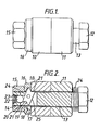
- FIG. 1 there is shown a connector device in accordance with the invention for bolting together two parts represented in the drawings by two abutting sleeve members 10,11.
- the device comprises a bolt member having a hexagonal head 12 and a shank 13 which is threaded at 14 along its length from the free end thereof.
- a hexagonal nut 15 cooperates with the threaded portion of the shank 13 which projects from an end face of part 10 after the shank has been inserted through the aligned apertures in parts 10 and 11.
- An annular spacer member 16 is also provided on the projecting portion of the shank 13 and is disposed between the nut 15 and the part 10.
- the spacer has an axially projecting annular flange 17, the free end of which engages an end face of the part 10.
- an annular space 18 is defined around the periphery of the shank 13 adjacent the part 10 for a purpose to be described below.
- the connector device also includes a latching mechanism provided by a pawl 19 rotatably mounted in a transverse slot 20 in the Shank 13 near the free end thereof.
- the pawl is generally rectangular but has notches 21 provided in a pair of opposite shorter ends thereof.
- the rotary position of the pawl is controlled by spring-loaded ball 22 which is disposed in a further slot 23 in the free end of the shank 13, which intersects the slot 20.
- a compression spring 24 is provided on the shank 13 adjacent to the head 12 of the device to act between the head and the adjacent part 11. This spring could desirably be accommodated in the bolt head under compression.
- the shank 13 of the connector device is inserted into the aligned apertures in the parts 10 and 11 to be bolted together.
- the ball 22 then acts on the p awl to bring it into the position shown in Figure 3.
- Release of the connector device then results in the pawl being brought into its latching position as shown in Figure 2 by the action of compression spring 23.
- the two parts are held together with withdrawal of the connector device prevented by the pawl 19, a notched end 21 of which receives an inner edge of the part 10, as shown in Figure 2, thereby preventing rotation of the pawl and effecting the latched condition of the device.
- the spacer 16 is positioned )n the projecting threaded end of the shank and the nut 15 is threadedly engaged theeewith, as shown in Figure 2.
- the annular space 18 defined within the spacer member 16. accommodates the pawl 19, in its latched condition, preparatory to tightening of the nut 15 to effect the final rigid connection.
- the pawl 19 disengages from the part 10 and the clamping force is then effected by the nut 15 acting through the spacer 16.
- the nut and spacer are removed but withdrawal of the shank 13 from the parts 10 and 11 is prevented by the pawl 19 which is brought into its latched condition as shown in Figure 2 on any attempt to withdraw the shank 13.
- This causes the ball 22 to disengage from notch 21 and to act on one of the longer side surfaces 24 of the pawl, as shown in Figure 2.
- the pawl 19, after disengagement from part 10 is then rotated anti-clockwise by the action of the spring-loaded ball 22 so that it is in a position in which its opposite longer side surface 25 will abut the end face of part 10 on subsequent withdrawal of the shank through the aligned apertures in parts 10 and 11.
- two parts can be secured together by a connector device according to the invention such that the Initial insertion of the device without the tightening nut achieves an initial latch connection by -a simple insertion. operation.
- Final tightening of the device can then be achieved using the tightening nut.
- two parts can be initially located and held together by a simple operation without having to thread a nut onto a threaded shank.
- Final tightening. can then be achieved after the initial connection has been made, with a tightening nut.
- the reverse procedure for disconnecting the two parts is also facilitated for similar reasons.
- a further advantage is that the latching mechanism provides a safety catch in the event that the nut threaded onto the shank should fail.
- spacer 16 could be integral with the nut 15A (Fig. 3A) or indeed the annular space 18 could be provided by forming an internal chamfer at one end of a suitably sized nut 15B (Fig. 3B).
- each part can be removed in turn by manipulation of the shank 13 in order to disengage the latching mechanism therefrom.
- each of the parts can be removed in succession as required instead of .a complete disconnection of all of the parts once the locking nut has been removed.
Landscapes
- Engineering & Computer Science (AREA)
- General Engineering & Computer Science (AREA)
- Mechanical Engineering (AREA)
- Details Of Connecting Devices For Male And Female Coupling (AREA)
- Details Of Spanners, Wrenches, And Screw Drivers And Accessories (AREA)
- Massaging Devices (AREA)
- Sowing (AREA)
- Transplanting Machines (AREA)
Applications Claiming Priority (2)
| Application Number | Priority Date | Filing Date | Title |
|---|---|---|---|
| GB08419891A GB2161883B (en) | 1984-08-03 | 1984-08-03 | Releasable connector device |
| GB8419891 | 1984-08-03 |
Publications (2)
| Publication Number | Publication Date |
|---|---|
| EP0174072A2 true EP0174072A2 (de) | 1986-03-12 |
| EP0174072A3 EP0174072A3 (de) | 1988-01-07 |
Family
ID=10564915
Family Applications (1)
| Application Number | Title | Priority Date | Filing Date |
|---|---|---|---|
| EP85304834A Ceased EP0174072A3 (de) | 1984-08-03 | 1985-07-05 | Lösbare Verbindungsvorrichtung |
Country Status (3)
| Country | Link |
|---|---|
| EP (1) | EP0174072A3 (de) |
| JP (1) | JPS6145107A (de) |
| GB (1) | GB2161883B (de) |
Cited By (3)
| Publication number | Priority date | Publication date | Assignee | Title |
|---|---|---|---|---|
| GB2238571A (en) * | 1989-11-01 | 1991-06-05 | Grayston Central Services | Scaffolding;latching |
| DE4019064A1 (de) * | 1990-06-15 | 1991-12-19 | Amazonen Werke Dreyer H | Axiales sicherungselement |
| EP1225346A1 (de) * | 2001-01-22 | 2002-07-24 | McKechnie Specialist Products Limited | Befestigungsvorrichtung |
Families Citing this family (2)
| Publication number | Priority date | Publication date | Assignee | Title |
|---|---|---|---|---|
| GB2220437A (en) * | 1987-12-09 | 1990-01-10 | Baj Ltd | Latch mechanisms |
| DE68920790D1 (de) * | 1988-07-21 | 1995-03-09 | Latchways Ltd | Lösbare Vorrichtungen zum Klemmen, Verriegeln, Verbinden oder Stützen. |
Family Cites Families (8)
| Publication number | Priority date | Publication date | Assignee | Title |
|---|---|---|---|---|
| GB212370A (en) * | 1923-02-01 | 1924-03-13 | George Henry Tonks | An improved device or apparatus for fastening plates such as those employed in a gasometer, boiler, ship and other constructions and which is applicable for uniting various objects |
| BE429744A (de) * | 1936-10-13 | |||
| GB500632A (en) * | 1937-08-12 | 1939-02-13 | Henry Hawkins | Improvements in and connected with bolts |
| GB553142A (en) * | 1941-11-04 | 1943-05-10 | Short Brothers Rochester & Bedford Ltd | Improvements in or connected with the attachment of jigs or templates for marking-out, drilling or otherwise working upon sheet metal |
| GB1139807A (en) * | 1965-04-28 | 1969-01-15 | Michael John David Roberts | Hitch pin |
| FR2202552A5 (de) * | 1972-10-10 | 1974-05-03 | Standard Pressed Steel Co | |
| GB1601795A (en) * | 1978-02-28 | 1981-11-04 | Hi Shear Corp | Safety bolt |
| GB2079704B (en) * | 1980-06-18 | 1983-11-16 | Newnham Thomas Oliver | A coupling pin |
-
1984
- 1984-08-03 GB GB08419891A patent/GB2161883B/en not_active Expired
-
1985
- 1985-07-05 EP EP85304834A patent/EP0174072A3/de not_active Ceased
- 1985-08-01 JP JP16865185A patent/JPS6145107A/ja active Pending
Cited By (4)
| Publication number | Priority date | Publication date | Assignee | Title |
|---|---|---|---|---|
| GB2238571A (en) * | 1989-11-01 | 1991-06-05 | Grayston Central Services | Scaffolding;latching |
| GB2238571B (en) * | 1989-11-01 | 1994-03-09 | Grayston Central Services | Scaffolding |
| DE4019064A1 (de) * | 1990-06-15 | 1991-12-19 | Amazonen Werke Dreyer H | Axiales sicherungselement |
| EP1225346A1 (de) * | 2001-01-22 | 2002-07-24 | McKechnie Specialist Products Limited | Befestigungsvorrichtung |
Also Published As
| Publication number | Publication date |
|---|---|
| EP0174072A3 (de) | 1988-01-07 |
| JPS6145107A (ja) | 1986-03-05 |
| GB2161883B (en) | 1987-09-30 |
| GB8419891D0 (en) | 1984-09-05 |
| GB2161883A (en) | 1986-01-22 |
Similar Documents
| Publication | Publication Date | Title |
|---|---|---|
| US5207543A (en) | Connecting device with a nut and bolt to prevent loosening and losing the nut | |
| US5653605A (en) | Locking coupling | |
| CA2220818C (en) | Lockable turnbuckle assembly | |
| US5772373A (en) | Nut and locking device | |
| CA1294416C (en) | Printed circuit board mounting apparatus | |
| US7448823B2 (en) | Quick release shackle pin system | |
| US5779388A (en) | Printed circuit board retainer | |
| GB2214256A (en) | Fastener retainer assembly | |
| JPH0235222A (ja) | 迅速連結装置 | |
| EP0529172B1 (de) | Plattenverbindungsvorrichtung, positive Sicherung und Zustandanzeigeeinrichtung | |
| US4830530A (en) | Hold-down device | |
| EP0174072A2 (de) | Lösbare Verbindungsvorrichtung | |
| EP0304237B1 (de) | Verbindungselement | |
| US2642108A (en) | Safety locking device for nuts | |
| US4413876A (en) | Fail-safe electrical connection terminal and tightening tool | |
| GB2090627A (en) | Stud and socket fastener assembly | |
| JPH04230489A (ja) | 運動伝達遠隔制御組立体 | |
| GB1581095A (en) | Lock with two key-receiving members | |
| EP0961884B1 (de) | Schraubensicherungsanordnung | |
| US4065217A (en) | Nose tip locking device | |
| JP3017304B2 (ja) | ターンバックル | |
| WO1999041808A1 (en) | Connector assembly | |
| JPH0231609Y2 (de) | ||
| JPS62501827A (ja) | 回転レンチ工具 | |
| JP3423974B2 (ja) | ロック状態を目で確認できる締め具 |
Legal Events
| Date | Code | Title | Description |
|---|---|---|---|
| PUAI | Public reference made under article 153(3) epc to a published international application that has entered the european phase |
Free format text: ORIGINAL CODE: 0009012 |
|
| AK | Designated contracting states |
Kind code of ref document: A2 Designated state(s): DE FR IT NL SE |
|
| PUAL | Search report despatched |
Free format text: ORIGINAL CODE: 0009013 |
|
| AK | Designated contracting states |
Kind code of ref document: A3 Designated state(s): DE FR IT NL SE |
|
| 17P | Request for examination filed |
Effective date: 19880130 |
|
| 17Q | First examination report despatched |
Effective date: 19880714 |
|
| STAA | Information on the status of an ep patent application or granted ep patent |
Free format text: STATUS: THE APPLICATION HAS BEEN REFUSED |
|
| 18R | Application refused |
Effective date: 19891211 |
|
| RIN1 | Information on inventor provided before grant (corrected) |
Inventor name: TUPPER, ALAN WILLIAM |