EP0174065B1 - Nassbeizung des Pflanzgutes - Google Patents
Nassbeizung des Pflanzgutes Download PDFInfo
- Publication number
- EP0174065B1 EP0174065B1 EP85304302A EP85304302A EP0174065B1 EP 0174065 B1 EP0174065 B1 EP 0174065B1 EP 85304302 A EP85304302 A EP 85304302A EP 85304302 A EP85304302 A EP 85304302A EP 0174065 B1 EP0174065 B1 EP 0174065B1
- Authority
- EP
- European Patent Office
- Prior art keywords
- tubers
- temperature
- conveyor
- water
- tuber
- Prior art date
- Legal status (The legal status is an assumption and is not a legal conclusion. Google has not performed a legal analysis and makes no representation as to the accuracy of the status listed.)
- Expired
Links
- 201000010099 disease Diseases 0.000 title claims description 13
- 208000037265 diseases, disorders, signs and symptoms Diseases 0.000 title claims description 13
- XLYOFNOQVPJJNP-UHFFFAOYSA-N water Substances O XLYOFNOQVPJJNP-UHFFFAOYSA-N 0.000 claims abstract description 63
- 239000012530 fluid Substances 0.000 claims abstract description 18
- 238000001816 cooling Methods 0.000 claims abstract description 16
- 238000007669 thermal treatment Methods 0.000 claims abstract description 16
- 244000061456 Solanum tuberosum Species 0.000 claims abstract description 15
- 235000002595 Solanum tuberosum Nutrition 0.000 claims abstract description 15
- 238000000034 method Methods 0.000 claims abstract description 11
- 238000010438 heat treatment Methods 0.000 claims description 8
- 239000012809 cooling fluid Substances 0.000 claims description 5
- 239000002689 soil Substances 0.000 claims description 4
- 238000012544 monitoring process Methods 0.000 claims description 3
- 239000005418 vegetable material Substances 0.000 claims description 3
- 230000035899 viability Effects 0.000 claims description 3
- 238000004140 cleaning Methods 0.000 claims description 2
- 230000000694 effects Effects 0.000 claims description 2
- 238000011144 upstream manufacturing Methods 0.000 claims 1
- 239000000463 material Substances 0.000 description 5
- 241000196324 Embryophyta Species 0.000 description 4
- 239000003570 air Substances 0.000 description 4
- 238000001035 drying Methods 0.000 description 4
- 230000006378 damage Effects 0.000 description 3
- 239000004033 plastic Substances 0.000 description 3
- 229920003023 plastic Polymers 0.000 description 3
- 239000012080 ambient air Substances 0.000 description 2
- 238000007654 immersion Methods 0.000 description 2
- 239000000126 substance Substances 0.000 description 2
- 239000002344 surface layer Substances 0.000 description 2
- 238000012546 transfer Methods 0.000 description 2
- 235000013311 vegetables Nutrition 0.000 description 2
- 241001274890 Boeremia exigua Species 0.000 description 1
- 241001273338 Boeremia foveata Species 0.000 description 1
- 208000001840 Dandruff Diseases 0.000 description 1
- 241000588698 Erwinia Species 0.000 description 1
- 206010061217 Infestation Diseases 0.000 description 1
- 241000219745 Lupinus Species 0.000 description 1
- 244000141359 Malus pumila Species 0.000 description 1
- 241000244206 Nematoda Species 0.000 description 1
- 239000004952 Polyamide Substances 0.000 description 1
- 239000004743 Polypropylene Substances 0.000 description 1
- 239000004793 Polystyrene Substances 0.000 description 1
- 241000813090 Rhizoctonia solani Species 0.000 description 1
- 206010039509 Scab Diseases 0.000 description 1
- 241001219481 Spongospora subterranea Species 0.000 description 1
- 208000027418 Wounds and injury Diseases 0.000 description 1
- 230000009471 action Effects 0.000 description 1
- 235000021016 apples Nutrition 0.000 description 1
- 239000007864 aqueous solution Substances 0.000 description 1
- 239000011324 bead Substances 0.000 description 1
- 230000005540 biological transmission Effects 0.000 description 1
- 238000007664 blowing Methods 0.000 description 1
- 239000013043 chemical agent Substances 0.000 description 1
- 238000011109 contamination Methods 0.000 description 1
- 238000011161 development Methods 0.000 description 1
- 235000013399 edible fruits Nutrition 0.000 description 1
- 238000002474 experimental method Methods 0.000 description 1
- 230000006698 induction Effects 0.000 description 1
- 208000014674 injury Diseases 0.000 description 1
- 238000007689 inspection Methods 0.000 description 1
- 238000009413 insulation Methods 0.000 description 1
- 239000010410 layer Substances 0.000 description 1
- 230000007774 longterm Effects 0.000 description 1
- 238000012986 modification Methods 0.000 description 1
- 230000004048 modification Effects 0.000 description 1
- 230000003071 parasitic effect Effects 0.000 description 1
- 244000052769 pathogen Species 0.000 description 1
- 229920002647 polyamide Polymers 0.000 description 1
- -1 polypropylene Polymers 0.000 description 1
- 229920001155 polypropylene Polymers 0.000 description 1
- 229920002223 polystyrene Polymers 0.000 description 1
- 231100000683 possible toxicity Toxicity 0.000 description 1
- 235000012015 potatoes Nutrition 0.000 description 1
- 230000005855 radiation Effects 0.000 description 1
- 238000005057 refrigeration Methods 0.000 description 1
- 230000004044 response Effects 0.000 description 1
- 230000000717 retained effect Effects 0.000 description 1
- 238000005096 rolling process Methods 0.000 description 1
- 239000000243 solution Substances 0.000 description 1
- 238000005507 spraying Methods 0.000 description 1
- WJCNZQLZVWNLKY-UHFFFAOYSA-N thiabendazole Chemical compound S1C=NC(C=2NC3=CC=CC=C3N=2)=C1 WJCNZQLZVWNLKY-UHFFFAOYSA-N 0.000 description 1
- 229960004546 thiabendazole Drugs 0.000 description 1
- 235000010296 thiabendazole Nutrition 0.000 description 1
- 239000004308 thiabendazole Substances 0.000 description 1
Images

Classifications
-
- A—HUMAN NECESSITIES
- A01—AGRICULTURE; FORESTRY; ANIMAL HUSBANDRY; HUNTING; TRAPPING; FISHING
- A01C—PLANTING; SOWING; FERTILISING
- A01C1/00—Apparatus, or methods of use thereof, for testing or treating seed, roots, or the like, prior to sowing or planting
- A01C1/08—Immunising seed
-
- A—HUMAN NECESSITIES
- A23—FOODS OR FOODSTUFFS; TREATMENT THEREOF, NOT COVERED BY OTHER CLASSES
- A23N—MACHINES OR APPARATUS FOR TREATING HARVESTED FRUIT, VEGETABLES OR FLOWER BULBS IN BULK, NOT OTHERWISE PROVIDED FOR; PEELING VEGETABLES OR FRUIT IN BULK; APPARATUS FOR PREPARING ANIMAL FEEDING- STUFFS
- A23N12/00—Machines for cleaning, blanching, drying or roasting fruits or vegetables, e.g. coffee, cocoa, nuts
Definitions
- the present invention relates to the treatment of plant diseases and in particular to the treatment of temperature sensitive diseases such as blackleg and softrot (caused by Erwinia Supp.) in potato tubers and other diseases in like plant matter.
- temperature sensitive diseases such as blackleg and softrot (caused by Erwinia Supp.) in potato tubers and other diseases in like plant matter.
- FR-A-2,400,840 discloses an apparatus suit- . able for use in the treatment of tubers and/or other like vegetable material of generally similarform so as to control disease therein, which apparatus comprises a vessel having a water holding zone, an endless conveyor means formed and arranged for conveying said tubers or the like along a conveying path having a substantial portion within said water holding zone between conveyor loading station and a conveyor discharge station; and conveyor drive control means formed and arranged for controlling the speed of said conveyor means so as to determine the transit time between said loading and discharge stations thereby determining the residence time in said water holding zone, said conveyor means having tuber support and retaining means of generally open-work structural form so as to permit water flow therethrough to substantially all sides of said tubers, said conveyor means being further formed and arranged so as to tumble and/or roll said tubers at least along a substantial part of said conveyor path portion.
- DE-C-436-090 discloses an apparatus suitable for use in a low temperature (not above 45°C) fluid treatment of grain and lupins and also mentions the possibility of treating potatoes.
- the apparatus uses screw conveyors to agitate the grain but does not suggest the conveying of material to be treated along a predetermined conveying path to obtain a carefully controlled treatment of all parts of the material.
- the present invention provides a method of treatment of potato blackleg in potato tubers comprising the steps of: grading potato tubers according to size, preferably to within a size variation of 20%, bringing size-graded potato tubers of a similar size, at a temperature at or below ambient temperature, preferably within the range from 4 to 30°C, most preferably from 4 to 20°C, to a thermal treatment zone; introducing said tubers into a body of thermal treatment fluid having a thermal capacity substantially largerthan that of said introduced tubers such that said introduced tubers have a substantially negligible effect on the temperature of said fluid which fluid is at a temperature of from 45 to 65°C, preferably from 50 to 65°C, most 'preferably from 50 to 56°C, so as to substantially wholly surround the individual tubers with said fluid, and retaining said tubers in said fluid for a period of time sufficient to substantially kill the blackleg organism without significantly damaging thetubertissue; withdrawing said tubers from said fluid and bringing them to a cooling zone; and preferably introducing said tubers into
- the tubers are preferably immersed in said fluid for a period of from 30 seconds at a temperature in the region of 65°C to 10 minutes at a temperature in the region of 50°C.
- the cooling step is preferably carried out so that said tubers are cooled to said temperature within a period of not more than 15 minutes, preferably from 4 to 12 minutes, e.g. 5 to 10 minutes. In practice it will often be sufficient to use ambient air, optionally with assisted flow, as the cooling fluid.
- the thermal treatment is carried out under temperature and time conditions such that substantially only the outer, extra-vascular, region of the tuber is heated.
- the thermal treatment is carried out under temperature and time conditions such that the viability of the tuber with respect to sprouting is substantially unimpaired although in the case of ware tubers this is of course not essential.
- the tubers are treated shortly after lifting, e.g. within 1 month, in order to minimise any development of disease in the tubers and to maximise viability especially in relation to sprouting.
- the tubers may be successfully treated in accordance with the invention up to 3 months or even 6 months after lifting.
- the present invention provides an apparatus suitable for use in the method of the present invention in the treatment of tubers and/or other like vegetable material of generally similar form, which apparatus comprises a vessel, having a water holding zone, an endless conveyor means formed and arranged for conveying said tubers or the like along a conveying path having a substantial portion within said water holding zone between a conveyor loading station and a conveyor discharge station; and conveyor drive control means formed and arranged for controlling the speed of said conveyor means so as to determine the transit time between said loading and discharge stations thereby determining the residence time in said water holding zone, said conveyor means having tuber support and retaining means of generally open-work structural form so as to permit water flow therethrough to substantially all sides of said tubers, said conveyor means being further formed and arranged so as to tumble and/or roll said tubers at least along a substantial part of said conveyor path portion, characterised in that said apparatus is provided with water circulation means formed and arranged for circulating water, in use of said apparatus, so as to circulate water through said conveyor path portion, water heating means formed and
- an apparatus of the present invention it is possible to thermally treat tubers and the like against temperature sensitive diseases in a closely controlled manner such as to permit substantially complete and effective treatment on a continuous basis of large amounts of tubers without significant injury to the tissue of the tuber.
- the conveyor means is in the form of a wheel having axially outer annular end wall means and radially outward wall means, and a plurality of generally radially extending compartment defining wall means for defining a plurality of circumferentially disposed tuber holding compartments between said annular end wall means and radially outward wall means, and provided with radially inward wall means formed and arranged to retain said tubers within said compartments between said loading and discharge stations whilst permitting entry and exit, respectively,at said said said stations.
- the water circulation means may be in the form of one or more discrete units but could also be constituted by suitably disposed heating means whereby water circulation is effected by convection currents and/or by the conveyor means whereby water circulation is effected by movement of the water by the conveyor means during movement of the conveyor means.
- the conveyor drive control means includes temperature sensor means formed and arranged for substantially continuously monitoring, in use, the temperature of the water during conveying of tubers thereth rough, and is arranged for varying the speed of the conveyor means in a predetermined proportional relation to the temperature whereby the transit time of the tubers is varied in an inverse relation with respect to said temperatures.
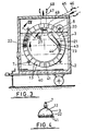
- Fig. 1 shows an apparatus 1 suitable for use in the treatment of potato blackleg.
- the apparatus 1 comprises a thermally insulated tank 2 having mounted therein a conveyor means 3.
- the conveyor means 3 is in the form of a large wheel 4 having along its outer circumference 5 an outwardly facing general U-shaped section guide channel 6 engaged by a plurality of circumferentially spaced apart guide wheels 7 and one or more drive wheels 8.
- the wheel 4 is mounted in a vertical plane with a small outer portion 9 extending above a water holding zone 10 below the water level line 11.
- the wheel 4 has a generally hemicylindrical section (see Fig. 2) and is subdivided by divider plates 12 which extend radially, into a plurality of tuber receiving compartments 13.
- the radially outer sides 14 of the compartments are defined substantially by a plurality of substantially spaced apart flexible elements such as plastic covered rope 15.
- the radially inner sides 16 of the compartments are partly open 17 and partly enclosed at the downstream ends 18 by a plurality of spaced apart axially extending elements 19 (note that the elements 15 and 19 of only some of the individual compartments are shown).
- the drive motor 20 is connected by a suitable transmission means to the drive wheel 8 for rotating the wheel 4 clockwise (as viewed in Fig. 1).
- the loading chute 21 extends downwardly into the water holding zone 10 to feed tubers 22 into the wheel, at a conveyor loading station 23 positioned so that the tubers fall gently into the compartments 13 and are retained therein, as the individual compartments traverse a conveyor path 24 through the water holding zone 10.
- the latter is urged into its loading position by resilient biasing means 26 so that if a tuber should become trapped, the chute backs away from the wheel riding over the trapped tuber 22.
- a discharge chute 27 which is mounted so as to catch tubers falling out of the compartments as these traverse the uppermost part of the conveyor path.
- the tank 2 is also provided with water heating means, conveniently in the form of one or more immersion heaters 28 and water circulation means, for example a water pump 29 mounted in a water circulation conduit 30.
- water heating means conveniently in the form of one or more immersion heaters 28 and water circulation means, for example a water pump 29 mounted in a water circulation conduit 30.
- water circulation means for example a water pump 29 mounted in a water circulation conduit 30.
- the tank 2 is also provided with a temperature sensor 31 connected to a control means 32 for continuously monitoring the water temperature and varying the speed of the motor 20 in response thereto so as to adjust the tuber residence time in the water in accordance with any variance in temperature of the water, so as to ensure at all times an optimum thermal treatment of the tubers.
- a hydraulic motor or possibly a pneumatic motor is found to be particularly suitable. It will be appreciated that as the tubers are carried round along the conveyor path 24 by the wheel 4 they are subjected to a gentle tumbling action and also to a continuous flow of water thereover thereby ensuring a substantially rapid and even thermal transfer between the water and the surface layer of the tuber.
- the discharge conveyor 27 extends to a cooling apparatus (not shown) formed and arranged for rapid cooling of the tubers.
- the cooling apparatus comprises tuber conveyor means, conveniently in the form of a pintle belt with upstanding rubber or other more or less soft resilient deformable fingers on which the tubers are supported as they pass through a cooling zone in which cold air is blown over and around them by suitable air flow induction means such as fans to provide a rapid cooling and all-over drying of the tubers.
- suitable air flow induction means such as fans to provide a rapid cooling and all-over drying of the tubers.
- these could be conveyed into a further apparatus substantially similar to that shown in fig. 1 in which, though, the water is maintained at a relatively low temperature e.g. 5°C, and the heating elements 28 are replaced by refrigeration elements. If required, the tubers could then be subsequently dried by blowing air over them.
- the wheel 4 is preferably constructed of materials having a relatively low thermal capacity in order to limit heat loss at the upper section of the conveyor path. Where the apparatus is to be used for smaller sized plant matter such as for example flower bulbs, then the mesh size of the compartment walls would need to be reduced.
- the tank 2 is mounted on a wheel chassis 40 suitable for towing by a motor vehicle so that the apparatus can be readily moved between different sites as required for use in treatment of tubers lifted at different places.
- the radially inner periphery of the wheel 3 is open and instead there is provided a fixed support in the form of a plurality of elongate arcuate round section elements 41 disposed in side-by-side relationship adjacent the radially inner edges 42 of the divider plates 12 of the wheel 3.
- the elements 41 are in the form of tubes of a plastics material such as a polyamide or polypropylene which is relatively wear resistant and forms a low friction contact with the divider plates 12 which conveniently are made of rigid or semi-rigid rubber or plastics. This arrangement has been found to be particularly gentle on the tubers being treated.
- the fixed elements 41 are splayed out at one end 43 to form a hopper 44 for receiving tubers at the loading station 23 from the loading chute 21, and extend around the inner periphery of the wheel 3 in sliding contact with the divider plates 12 up to the discharge station 27, so as to define together with the wheel 3 a plurality of tuber receiving compartments 13.
- the loading chute 21 is connected to a loading conveyor 45 (indicated schematically) which conveys the tubers 22 through a cleaning station 46 where any soil is removed to a greater or lesser extent in order to maximise thermal contact of the heated water 10 with the tuber itself during the thermal treatment.
- the tubers are washed by spraying and/or immersion and desirably passed though a water bath in which they are subjected to ultrasonic radiation which assists in removal of the soil.
- a suitable belt conveyor 47 for conveying the thermally treated tubers to a cooling and optionally drying also, station 48.
- the tubers are cooled and dried sufficiently rapidly by passage along a short conveyor run of a few metres through ambient air so that they may be conveyed directly to a bagging station and cooling and drying allowed to continue naturally in the sacks especially where these are of hessian or like woven material.
- a mechanically assisted air flow through or across the discharge conveyor 47 downstream of the tank 2.
- the tank 2 is normally provided with an insulated roof 49 to help maintain a uniform temperature and conserve energy. Suitable inlet and outlet openings, inspection hatches etc are provided as required and provided with suitable seals etc.
- the drive system 20, 8 may be driven by any suitable means such as for example an electric or more conveniently a hydraulic motor to provide a suitable rate of rotation e.g. about r.p.m. to provide a residence time of 3 minutes in a typical arrangement using a 10 m 3 capacity tank holding some 8 tonnes of water. This can achieve a treatment rate of the order of 3 tonnes of tubers per hour.
- the treatment water may include suitable chemicals for simultaneous treatment of other possible conditions such as potato gangrene (Phoma exigua), black scurf (Rhizoctonia solani), powdery scab (Spongospora subterranea) etc which might also be present.
- potato gangrene Phoma exigua
- black scurf Rhizoctonia solani
- powdery scab Spongospora subterranea
- thiabendazole may be included in the treatment water.
- Typical conditions which have been found satisfactorily maintained sprouting ability were 3 mins at 55°C and 5 mins at 52°C.
- Advantageously filter means may be provided, conveniently in the water circulation means, for avoiding buildup of soil shed from the tubers in the tank. It may also be noted that where a longer treatment time e.g. up to 30 mins would be acceptable then a treatment temperature as low as 45°C could be used.
Landscapes
- Life Sciences & Earth Sciences (AREA)
- Soil Sciences (AREA)
- Environmental Sciences (AREA)
- Chemical & Material Sciences (AREA)
- Engineering & Computer Science (AREA)
- Food Science & Technology (AREA)
- Polymers & Plastics (AREA)
- Pretreatment Of Seeds And Plants (AREA)
- Agricultural Chemicals And Associated Chemicals (AREA)
- Medicines Containing Plant Substances (AREA)
- Preparation Of Fruits And Vegetables (AREA)
Claims (13)
Priority Applications (1)
| Application Number | Priority Date | Filing Date | Title |
|---|---|---|---|
| AT85304302T ATE47642T1 (de) | 1984-06-16 | 1985-06-17 | Nassbeizung des pflanzgutes. |
Applications Claiming Priority (2)
| Application Number | Priority Date | Filing Date | Title |
|---|---|---|---|
| GB848415432A GB8415432D0 (en) | 1984-06-16 | 1984-06-16 | Plant disease treatment |
| GB8415432 | 1984-06-16 |
Publications (2)
| Publication Number | Publication Date |
|---|---|
| EP0174065A1 EP0174065A1 (de) | 1986-03-12 |
| EP0174065B1 true EP0174065B1 (de) | 1989-11-02 |
Family
ID=10562573
Family Applications (1)
| Application Number | Title | Priority Date | Filing Date |
|---|---|---|---|
| EP85304302A Expired EP0174065B1 (de) | 1984-06-16 | 1985-06-17 | Nassbeizung des Pflanzgutes |
Country Status (5)
| Country | Link |
|---|---|
| EP (1) | EP0174065B1 (de) |
| AT (1) | ATE47642T1 (de) |
| DE (1) | DE3573975D1 (de) |
| GB (1) | GB8415432D0 (de) |
| IE (1) | IE56682B1 (de) |
Family Cites Families (4)
| Publication number | Priority date | Publication date | Assignee | Title |
|---|---|---|---|---|
| DE436090C (de) * | 1926-10-26 | Ferdinand Kraemer | Vorrichtung zum Nassbeizen von Getreide und Entbittern von Lupinen | |
| DE373606C (de) * | 1923-04-13 | Gelochter Bleche Mayer & Co Fa | Vorrichtung zur Ausscheidung von ungesunden Koernern beim Beizen von Saatgetreide | |
| GB871272A (en) * | 1958-09-17 | 1961-06-28 | Aagrunol Chemische Fabrieken N | An improved device for treating seeds with liquids and liquid suspensions |
| FR2400840A1 (fr) * | 1976-07-30 | 1979-03-23 | Morillon Theodore | Machine pour le traitement par bain en continu de legumes ou de fruits |
-
1984
- 1984-06-16 GB GB848415432A patent/GB8415432D0/en active Pending
-
1985
- 1985-06-14 IE IE1489/85A patent/IE56682B1/xx unknown
- 1985-06-17 AT AT85304302T patent/ATE47642T1/de not_active IP Right Cessation
- 1985-06-17 DE DE8585304302T patent/DE3573975D1/de not_active Expired
- 1985-06-17 EP EP85304302A patent/EP0174065B1/de not_active Expired
Also Published As
| Publication number | Publication date |
|---|---|
| GB8415432D0 (en) | 1984-07-18 |
| DE3573975D1 (en) | 1989-12-07 |
| IE851489L (en) | 1985-12-16 |
| IE56682B1 (en) | 1991-11-06 |
| EP0174065A1 (de) | 1986-03-12 |
| ATE47642T1 (de) | 1989-11-15 |
Similar Documents
| Publication | Publication Date | Title |
|---|---|---|
| US6442866B2 (en) | Method and apparatus for drying or heat-treating products | |
| US5329842A (en) | Combination blancher and cooler | |
| US12402639B2 (en) | Modular produce drying tunnel and methods of use | |
| US2692200A (en) | Apparatus for and method of blanching vegetables | |
| US3250086A (en) | Chilling apparatus | |
| US2419876A (en) | Dehydration apparatus having conveyors, agitators, radiant heaters, and gas circulating means | |
| HUE025591T2 (en) | Microwave Vacuum Organic Dryer | |
| CA2087418C (en) | Continuous process cooker/blancher | |
| US2456124A (en) | Apparatus for and method of treating food products | |
| EP0239284B1 (de) | Behandlung von Knollenfrüchten | |
| WO2017021735A1 (en) | Pasteurisation | |
| US3004407A (en) | Continuous poultry chiller apparatus and method | |
| US20040231184A1 (en) | Dried food product | |
| EP0174065B1 (de) | Nassbeizung des Pflanzgutes | |
| CN103947741A (zh) | 果实采后热激处理保鲜装置及方法 | |
| US5220802A (en) | Method and apparatus for individually quick freezing small surface moist articles | |
| US4563364A (en) | Method for steam blanching foodstuffs in a pressure vessel | |
| EP1653816B1 (de) | Gerät und verfahren für die behandlung von nahrungsmitteln mit einem gasförmigen medium für die verarbeitung und anschliessende trocknung | |
| US1443367A (en) | Apparatus for dehydrating fruit, vegetables, and other materials | |
| KR101655880B1 (ko) | 신속 낱잎 김치 제조시스템 | |
| JPS6244908B2 (de) | ||
| US3875677A (en) | Method and apparatus for heating thermoplastic yarn | |
| US5168723A (en) | Method and apparatus for individually quick freezing small surface moist articles | |
| HU218311B (en) | Equipment for heat treatment of food in particular for cooking of greens | |
| US2878821A (en) | Continuous automatic dipping tank |
Legal Events
| Date | Code | Title | Description |
|---|---|---|---|
| PUAI | Public reference made under article 153(3) epc to a published international application that has entered the european phase |
Free format text: ORIGINAL CODE: 0009012 |
|
| AK | Designated contracting states |
Kind code of ref document: A1 Designated state(s): AT BE CH DE FR GB IT LI LU NL SE |
|
| 17P | Request for examination filed |
Effective date: 19860912 |
|
| 17Q | First examination report despatched |
Effective date: 19871209 |
|
| GRAA | (expected) grant |
Free format text: ORIGINAL CODE: 0009210 |
|
| AK | Designated contracting states |
Kind code of ref document: B1 Designated state(s): AT BE CH DE FR GB IT LI LU NL SE |
|
| REF | Corresponds to: |
Ref document number: 47642 Country of ref document: AT Date of ref document: 19891115 Kind code of ref document: T |
|
| REF | Corresponds to: |
Ref document number: 3573975 Country of ref document: DE Date of ref document: 19891207 |
|
| ET | Fr: translation filed | ||
| ITF | It: translation for a ep patent filed | ||
| PLBE | No opposition filed within time limit |
Free format text: ORIGINAL CODE: 0009261 |
|
| STAA | Information on the status of an ep patent application or granted ep patent |
Free format text: STATUS: NO OPPOSITION FILED WITHIN TIME LIMIT |
|
| 26N | No opposition filed | ||
| PGFP | Annual fee paid to national office [announced via postgrant information from national office to epo] |
Ref country code: FR Payment date: 19910625 Year of fee payment: 7 |
|
| PGFP | Annual fee paid to national office [announced via postgrant information from national office to epo] |
Ref country code: SE Payment date: 19910627 Year of fee payment: 7 |
|
| ITTA | It: last paid annual fee | ||
| PGFP | Annual fee paid to national office [announced via postgrant information from national office to epo] |
Ref country code: NL Payment date: 19910630 Year of fee payment: 7 Ref country code: AT Payment date: 19910630 Year of fee payment: 7 |
|
| PGFP | Annual fee paid to national office [announced via postgrant information from national office to epo] |
Ref country code: DE Payment date: 19910723 Year of fee payment: 7 |
|
| PGFP | Annual fee paid to national office [announced via postgrant information from national office to epo] |
Ref country code: CH Payment date: 19910730 Year of fee payment: 7 |
|
| PGFP | Annual fee paid to national office [announced via postgrant information from national office to epo] |
Ref country code: LU Payment date: 19910806 Year of fee payment: 7 Ref country code: BE Payment date: 19910806 Year of fee payment: 7 |
|
| EPTA | Lu: last paid annual fee | ||
| PG25 | Lapsed in a contracting state [announced via postgrant information from national office to epo] |
Ref country code: LU Free format text: LAPSE BECAUSE OF NON-PAYMENT OF DUE FEES Effective date: 19920617 Ref country code: AT Effective date: 19920617 |
|
| PG25 | Lapsed in a contracting state [announced via postgrant information from national office to epo] |
Ref country code: SE Effective date: 19920618 |
|
| PG25 | Lapsed in a contracting state [announced via postgrant information from national office to epo] |
Ref country code: LI Effective date: 19920630 Ref country code: CH Effective date: 19920630 Ref country code: BE Effective date: 19920630 |
|
| BERE | Be: lapsed |
Owner name: ABERDEEN BIO-TECH LTD Effective date: 19920630 |
|
| PG25 | Lapsed in a contracting state [announced via postgrant information from national office to epo] |
Ref country code: NL Effective date: 19930101 |
|
| GBPC | Gb: european patent ceased through non-payment of renewal fee |
Effective date: 19920617 |
|
| NLV4 | Nl: lapsed or anulled due to non-payment of the annual fee | ||
| PG25 | Lapsed in a contracting state [announced via postgrant information from national office to epo] |
Ref country code: FR Effective date: 19930226 |
|
| REG | Reference to a national code |
Ref country code: CH Ref legal event code: PL |
|
| PG25 | Lapsed in a contracting state [announced via postgrant information from national office to epo] |
Ref country code: DE Effective date: 19930302 |
|
| REG | Reference to a national code |
Ref country code: FR Ref legal event code: ST |
|
| REG | Reference to a national code |
Ref country code: GB Ref legal event code: 728C |
|
| EUG | Se: european patent has lapsed |
Ref document number: 85304302.4 Effective date: 19930109 |
|
| PGFP | Annual fee paid to national office [announced via postgrant information from national office to epo] |
Ref country code: GB Payment date: 19961119 Year of fee payment: 12 |
|
| REG | Reference to a national code |
Ref country code: GB Ref legal event code: 728Y |
|
| PG25 | Lapsed in a contracting state [announced via postgrant information from national office to epo] |
Ref country code: GB Free format text: LAPSE BECAUSE OF NON-PAYMENT OF DUE FEES Effective date: 19970617 |
|
| GBPC | Gb: european patent ceased through non-payment of renewal fee |
Effective date: 19970617 |